Nortek PPA3RE Series Installation Instructions Manual
Single package air conditioner - single stage, r-410a
Hide thumbs
Also See for PPA3RE Series:
- Installation instructions manual (20 pages) ,
- Installation instructions manual (20 pages) ,
- Installation instructions manual (20 pages)
Table of Contents
Advertisement
P7re / PPa3re SerieS
inStallation inStructionS
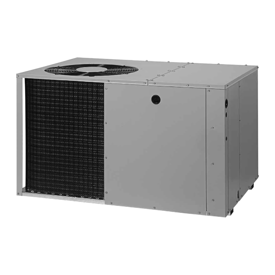
Single Package air conditioner - Single Stage, r-410a
it is your responsibility to know this product better than your customer. this includes being
able to install the product according to strict safety guidelines and instructing the customer on
how to operate and maintain the equipment for the life of the product. Safety should always be
the deciding factor when installing this product and using common sense plays an important
role as well. Pay attention to all safety warnings and any other special notes highlighted in the
manual. improper installation of the furnace or failure to follow safety warnings could result in
serious injury, death, or property damage.
these instructions are primarily intended to assist qualified individuals experienced in the proper
installation of this appliance. Some local codes require licensed installation/service personnel
for this type of equipment. Please read all instructions carefully before starting the installation.
return these instructions to the customer's package for future reference.
do not deStroY. PleaSe read careFullY & keeP in a SaFe Place For Future reFerence.
iMPortant
attention inStallerS:
14 Seer
Advertisement
Table of Contents

Subscribe to Our Youtube Channel
Related Manuals for Nortek PPA3RE Series


Summary of Contents for Nortek PPA3RE Series
- Page 1 P7re / PPa3re SerieS 14 Seer inStallation inStructionS Single Package air conditioner - Single Stage, r-410a iMPortant attention inStallerS: it is your responsibility to know this product better than your customer. this includes being able to install the product according to strict safety guidelines and instructing the customer on how to operate and maintain the equipment for the life of the product.
-
Page 2: Table Of Contents
table oF contentS Start uP & adJuStMentS ........10 iMPortant SaFetY inForMation .....3 Pre-Start Checklist ..........10 general inForMation ........4 Start-Up Procedure ..........10 Before You Install this Unit ........4 System Cooling ............10 Locating the Air Conditioner ........4 System Heating ............10 Minimum Clearance Requirements ......4 Charging the Unit in AC Mode .........10 Service Access Clearances .........4 Safety switches............11... -
Page 3: Important Safety Information
iMPortant SaFetY inForMation caution: Please read all instructions before servicing this equipment. Pay attention to all safety warnings and any other special this unit uses r-410a refrigerant. do not use notes highlighted in the manual. Safety markings are any other refrigerant in this unit. use of another used frequently throughout this manual to designate a refrigerant will damage the unit. -
Page 4: General Information
general inForMation • Consideration should also be given to availability of electric power, service access, noise, and shade. This packaged air conditioner is designed only for outdoor ground level installations and can be readily connected Minimum clearance requirements to the high static duct system of a home. This unit has Sufficient clearance for unobstructed airflow through the been tested for capacity and efficiency in accordance outdoor coil must be maintained in order to provide room... -
Page 5: Air Conditioner Installation
Single duct aPPlication MultiPle duct aPPlication Figure 2. Single & Multiple duct applications air conditioner inStallation • Duct work should be attached directly to the unit flanges for horizontal applications. unpacking the unit • For highly resistive duct systems it may be necessary It is recommended that the unit be unpacked at the to add an additional return air duct and or supply to installation site to minimize damage due to handling. -
Page 6: Return Duct
5. Tighten first screw and rotate collar clockwise so joint deep, it will only be necessary to cut a hole for the collar is near 3 o’clock position. on the return air box or for the insulated duct. 3. Set the box into the opening and fasten with screws or Return Duct nails. -
Page 7: Condensate Drainage
electrical connectionS 3. Cut a 9-1/8” x 13-1/8” hole in the duct and bend over all tabs flat on the inside of the heat duct. 4. Insert the damper into the duct and bend over all tabs Warning: flat on the inside of the heat duct. 5. -
Page 8: Grounding
overcurrent Protection • The unit requires both power and control circuit electrical Generally, the best fuse or breaker for any air conditioner connections. Refer to the wiring diagrams (Figure 10 is the smallest size that will permit the equipment to run (page 13) Figure 11 (page 14).) for identification... - Page 9 coPPer Wire SiZe — aWg recoMMended MaXiMuM (1% VoLTage Drop) Wire gauge Wire lengtH (Ft) FroM unit to tHerMoStat SuPPlY SuPPlY Wire lengtH-Feet circuit aMPacitY table 2. Control Wiring (24V) Wire Size based on N.E.C. for 60° type copper conductors. table 1.
-
Page 10: Blower Speed - Ecm Motor
blower Speed - ecM Motor Verify that the indoor blower, outdoor fan, and compressor energize and the cooling function starts. Warning: 5. Verify the discharge air grilles are adjusted and the system air is balanced. to prevent electric shock, personal injury, or 6. -
Page 11: Safety Switches
air conditioner Maintenance • If the pressure measured in step 1 is greater than the required liquid refrigerant pressure determined in step 3, then there is too much charge in the system. Remove Warning: refrigerant and repeat steps 1 through 3 until the system is correctly charged. -
Page 12: Figures & Tables
FigureS & tableS Top View “A” “B” 3” 5.5” Opening for Opening for 12" Diameter 12" Diameter Supply Duct Return Duct 9.15” 1" 3.15” 9” 17.50” rear View (2, 2.5, & 3 ton) 3” 1.75” Ø Electric Heater Power Supply 1.13”... -
Page 13: Wiring Diagrams
Wiring diagrams Figure 10. Wiring diagram (2 & 2.5 ton Models) - Page 14 Figure 11. Wiring diagram (3, 3.5, 4, & 5 ton Models)
-
Page 15: Refrigerant Charging Tables
refrigerant charging tables legend noteS: Shaded boxes indicate flooded conditions. 1. All pressures are listed psig and all temperatures in °F Rated design values. The suction pressure 2. Discharge temperatures greater than charted values will vary from design value if outdoor air indicate an undercharged system. -
Page 16: Table 6. Charging Table For 3 Ton Units
outdoor teMPerature (° F) Suct. PreSS. liq. diS. liq. diS. liq. diS. liq. diS. liq. diS. liq. diS. liq. diS. liq. diS. PreSS. teMP. PreSS. teMP. PreSS. teMP. PreSS. teMP. PreSS. teMP. PreSS. teMP. PreSS. teMP. PreSS. teMP. table 6. charging table for 3 ton units (036k Model) outdoor teMPerature (°... -
Page 17: Table 8. Charging Table For 4 Ton Units
outdoor teMPerature (° F) Suct. PreSS. liq. diS. liq. diS. liq. diS. liq. diS. liq. diS. liq. diS. liq. diS. liq. diS. PreSS. teMP. PreSS. teMP. PreSS. teMP. PreSS. teMP. PreSS. teMP. PreSS. teMP. PreSS. teMP. PreSS. teMP. table 8. charging table for 4 ton units (048k Model) 5-TON CHARGING CHART Remove refrigerant if above curve... -
Page 20: Installation / Performance Checklist
Fan Motor coMPonentS: • Blower Assembly • Fan Grille • Cabinet Panels • Filter/Driers • Expansion Valves Specifications & illustrations subject to change without notice or incurring obligations (03/15). © Nortek Global HVAC LLC 2015. All Rights Reserved. 709692c (Replaces 709692B)
Need help?
Do you have a question about the PPA3RE Series and is the answer not in the manual?
Questions and answers