Table of Contents
Advertisement
Quick Links
Advertisement
Table of Contents

Related Manuals for Asus J6412T-IM-A


Summary of Contents for Asus J6412T-IM-A
- Page 1 J6412T-IM-A...
- Page 2 Product warranty or service will not be extended if: (1) the product is repaired, modified or altered, unless such repair, modification of alteration is authorized in writing by ASUS; or (2) the serial number of the product is defaced or missing.
-
Page 3: Table Of Contents
Contents Chapter 1 Product overview Package contents ................. 1-1 Features ..................1-1 1.3 Specifications ................1-2 Chapter 2 Motherboard information Before you proceed ..............2-1 Motherboard layout ..............2-2 Central Processing Unit (CPU) ........... 2-4 System memory ................2-5 Jumpers ..................2-6 Connectors ................. - Page 4 3.3.15 EZ-Flash ............... 3-11 3.3.16 LVDS Configuration ............3-11 Hardware Monitor menu ............3-12 Security menu ................3-12 Boot menu .................. 3-14 Exit menu ..................3-14 Save Changes & Exit ..............3-14 Discard Changes & Exit ............... 3-14 Save Changes & Reset ..............3-15 Discard Changes &...
-
Page 5: Chapter 1 Product Overview
Chapter 1 Product overview Package contents Check your industrial motherboard package for the following items. 1 x ASUS J6412T-IM-A Motherboard 1 x SATA 6.0 Gb/s cable 1 x SATA power cable 2 x ASUS I/O Shield NOTE: If any of the above items is damaged or missing, contact your distributor or sales representative immediately. -
Page 6: Specifications
6 x Serial Port headers (5 x RS232, 1 x RS232/422/485) 1 x Chassis Fan header (PWM Mode) 1 x Chassis intrusion header Internal Connectors 1 x Front panel audio header (AAFP) 1 x System panel header (10-1 pin) 1 x Clear CMOS jumper (continued on the next page) J6412T-IM-A... - Page 7 2 x USB 2.0 headers support additional 4 USB 2.0 ports 1 x 8-bit GPIO header 1 x COM debug header 1 x 4-pin ATX 12V power connector 1 x SATA power connector 1 x SATA port 1 x PS/2 port 1 x Speaker header Internal Connectors...
-
Page 8: Chapter 2 Motherboard Information
Chapter 2 Motherboard information Before you proceed Take note of the following precautions before you install motherboard components or change any motherboard settings. CAUTION! • Unplug the power cord from the wall socket before touching any component. • Before handling components, use a grounded wrist strap or touch a safely grounded object or a metal object, such as the power supply case, to avoid damaging them due to static electricity. -
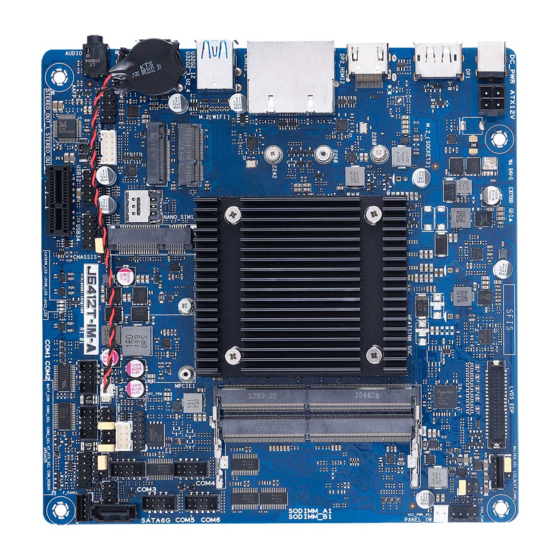
Page 9: Motherboard Layout
STEREO_OUT_L SD_CARD GPIO_CON KBMS_CON STEREO_OUT_R (BOTTOM) USB12 BATT_CON CHASSIS USB34 AAFP CLRTC1 AUDIO COM1 COM2 F_PANEL COM1_SEL PCIEX1 SPEAKER COM2_SEL NOTE: The audio codec may vary between motherboards, please consult your sales window for the motherboards’ exact codec type. J6412T-IM-A... - Page 10 Connectors/Jumpers/Slots Page ATX Power connector (4-pin ATX12V) 2-11 Built-in Intel Celeron Quad-core Processor J6412 ® ® SPI_TPM header (14-1 pin SPI_TPM) 2-21 DDR4 SO-DIMM slots LVDS/EDP header (40-pin LVDS_EDP) 2-16 LVDS Panel Backlight Enable Signal Selection (BKLTEN_SEL) LVDS Backlight Panel header (5-pin LCD_BLKT_PANEL) 2-15 Chassis fan header (4-pin CHA_FAN) 2-11...
-
Page 11: Central Processing Unit (Cpu)
Central Processing Unit (CPU) The motherboard comes with an onboard Intel processor J6412. ® Intel ® J6412 SoC J6412T-IM-A... -
Page 12: System Memory
• According to Intel CPU spec, DIMM voltage below 1.35V is recommended ® to protect the CPU. NOTE: Visit the ASUS website at www.asus.com for the latest QVL. To remove a SO-DIMM To install a SO-DIMM Chapter 2: Motherboard information... -
Page 13: Jumpers
Hold down the <Del> key during the boot process and enter BIOS setup to re-enter data. NOTE: If the steps above do not help, remove the onboard battery and move the jumper again to clear the CMOS RTC RAM data. After clearing the CMOS, reinstall the battery. J6412T-IM-A... - Page 14 AT/ATX mode selection jumper (3-pin AT_ATX_SEL) AT_ATX_SEL ATX MODE AT MODE (Default) Pins 1-2 (Default) ATX mode AT mode HEADER 1x3p, 2.54mm pitch, S/T Connector type COM Ring/+5V/+12V selection jumpers (6-pin COM1_SEL, COM2_SEL) COM1_SEL COM2_SEL (Default) Setting Pins Ring (Default) Chapter 2: Motherboard information...
- Page 15 Chassis Intruder - Open 3-4jumper closed 3-4jumper removed (Default) Connector type HEADER 4p, K2, 2.54mm pitch LVDS Panel VCC Power Selection jumper (6-pin VCC_PWR_SEL) VCC_PWR_SEL (Default) Setting Pins 1.4.5-6 1.4.5-3 3V (Default) 1.4.5-2 Connector type HEADER 1 x 3p, 2.54mm pitch, S/T J6412T-IM-A...
- Page 16 LVDS Panel Backlight Enable Signal Selection (BKLTEN_SEL) BKLTEN_SEL LCD_ENABKLT_S LCD_ENABKLT_S# (Default) Pins 12V (Default) Connector type HEADER 1x3p, 2.54mm pitch, S/T Internal Stereo Speaker header (2-pin STEREO_OUT_L, STEREO_ OUT_R) The internal mono speaker header allows connection to an internal, low-power speaker for basic system sound capability.
-
Page 17: Connectors
USB 3.2 Gen 2 (up to 10Gbps) ports. These 9-pin Universal Serial Bus (USB) ports are for USB 3.2 Gen 2 devices. USB 2.0 port. These Universal Serial Bus (USB) ports are for USB 2.0 devices. Audio port. This port connects to an audio device. J6412T-IM-A 2-10... -
Page 18: Internal Connectors
2.6.2 Internal connectors ATX Power connector (4-pin ATX12V) Correctly orient the ATX power supply plug into this connector and push down firmly until the connector completely fits. ATX12V DC_PWR DC_PWR PIN 1 Chassis Fan header (4-pin CHA_FAN) Connect the fan cable to the fan header on the motherboard, ensuring that the black wire of each cable matches the ground pin of the header. - Page 19 These headers are for USB 2.0 ports. Connect the USB cables to these headers. These USB headers comply with USB 2.0 specification that supports up to 480 Mbps connection speed. USB12 PIN 1 USB34 PIN 1 Connector type Header 2x5p, K9, 2.54mm pitch J6412T-IM-A 2-12...
- Page 20 CAUTION! Never connect a 1394 cable to the USB headers. Doing so will damage the motherboard. NOTE: The USB cables are purchased separately. SATA Power connector (4-pin SATA_PWR) This connector is for the SATA power cable. The power cable plug is designed to fit this connector in only one orientation.
- Page 21 SPEAKER PIN 1 Connector type HEADER 1x4p, 2.54mm pitch, S/T System Panel header (10-1 pin F_PANEL) This header supports several chassis-mounted functions. +PWR_LED PWR_BTN F_PANEL PIN 1 +HDD_LED RESET Connector type Header 2x5p, K10, 2.54mm pitch J6412T-IM-A 2-14...
- Page 22 • System power LED (2-pin +PWR_LED) This 2-pin header is for the system power LED. Connect the chassis power LED cable to this header. The system power LED lights up when you turn on the system power, and blinks when the system is in sleep mode. •...
- Page 23 PERST# mSATA_Present PERp0 3.3V_2 3.3V GND13 PERn0 GND14 GND9 NP_NC1 GND4 NP_NC2 1.5V_2 11. LVDS/EDP header (30-pin LVDS_EDP) This header is for an internal LVDS or embedded DisplayPort connection. PIN 1 PIN 39 LVDS_EDP PIN 2 PIN 40 J6412T-IM-A 2-16...
- Page 24 12. M.2 socket 3 (M.2_SOCKET3) This socket allows you to install an M.2 SSD module. M.2(SOCKET3) NOTES: • The M.2 SSD module is purchased separately. • This socket supports M Key and 2242/2260/2280 storage devices. 13. M.2 Wi-Fi slot This slot connects to an M.2 Wi-Fi device. M.2(WIFI) PIN 1 NOTE: The M.2 Wi-Fi module is purchased separately.
- Page 25 This header is for a general purpose input/output module which allows you to customize the digital signal input/output. GPIO_CON PIN 1 WAFER HD 2x5p, 2.0mm pitch, S/T Connector type 15. RTC Battery header (2-pin BATT_CON) This header is for the lithium CMOS battery. BATT_CON PIN 1 J6412T-IM-A 2-18...
- Page 26 16. Front Panel Audio header (10-1 pin AAFP) This header is for a chassis-mounted front panel audio I/O module that supports HD Audio standard. Connect one end of the front panel audio I/O module cable to this header. AAFP PIN 1 Connector type HEADER 2x5p, K8, 2.54mm pitch IMPORTANT!
- Page 27 COM1 COM2 PIN 1 COM3 Ring COM4 CTS# RTS# COM5 DSR# DTR# COM6 DCD# PIN 1 Connector type BOX header 2x5p, K10, 2.00mm pitch NOTE: The serial port cables are purchased separately. J6412T-IM-A 2-20...
- Page 28 20. SPI TPM header (14-1 pin TPM) This header supports a Trusted Platform Module (TPM) system with a Serial Peripheral Interface (SPI), allowing you to securely store keys, digital certificates, passwords, and data. A TPM system also helps enhance network security, protects digital identities, and ensures platform integrity.
- Page 29 PCIe 3.0/2.0 x1 slot (PCIEX1) This slot supports a PCIe 3.0/2.0 x1 graphics card that complies with the PCI Express specification. PCIEX1 PIN A1-A18 PIN B1-B18 J6412T-IM-A 2-22...
-
Page 30: Chapter 3 Bios Setup
Always shut down the system properly from the operating system. IMPORTANT: • Visit the ASUS website at www.asus.com to download the latest BIOS file for this motherboard. • The default BIOS settings for this motherboard apply to most working conditions and ensures optimal performance. -
Page 31: Bios Menu Screen
The Main menu provides you an overview of the basic system information, and allows you to set the system date, time, language, and security settings. 3.2.1 System Date [Day MM/DD/YYYY] Allows you to set the system date. 3.2.2 System Time [HH:MM:SS] Allows you to set the system time. J6412T-IM-A... -
Page 32: Advanced Menu
Advanced menu The Advanced menu items allow you to change the settings for the CPU and other system devices. Be cautious when changing the settings of the Advanced menu items. Incorrect field values can cause the system to malfunction. 3.3.1 PCH-FW Configuration TPM Device Selection This item allows you to select the TPM device. -
Page 33: Graphics Configuration
This item allows you to control the PCI Express root port. Configuration options: [Disabled] [Enabled] ASPM This item allows you to control the Active State Power Management on both NB (NorthBridge) side and SB (SouthBridge) side of the DMI Link. Configuration options: [Disable] [L0s] [L1] [L0sL1] [Auto] J6412T-IM-A... -
Page 34: Super Io Configuration
L1 Substates This item allows you to select the PCI Express L1 Substate settings. Configuration options: [Disabled] [L1.1] [L1.2] [L1.1 & L1.2] PCIe Speed Configures the speed of PCIEX16_2 slot. Configuration options: [Auto] [Gen1] [Gen2] [Gen3] Detect Timeout This item allows you to set the number of milliseconds to wait before assuming there is no device and potentially disabling the port. -
Page 35: Serial Console Redirection
0 if the num of 1’s in the data bits is even [Odd] parity bit is 0 if num of 1’s in the data bits is odd [Mark] parity bit is always 1 [Space] parity bit is always 0 J6412T-IM-A... -
Page 36: Sata Configuration
Stop Bits Stop bits indicate the end of a serial data packet. (A start bit indicates the beginning.) The standard setting is 1 stop bit. Communication with slow devices may require more than 1 stop bit. Configuration options: [1] [2] Flow Control Flow control can prevent data loss from buffer overflow. -
Page 37: Network Stack Configuration
Allows you to enable or disable the USB port. Once set to [Disabled], any USB devices plugged into the connector will not be detected by BIOS or OS. Configuration options: [Disabled] [Enabled] 3.3.11 NVMe Configuration This page displays the NVMe controller and drive information. J6412T-IM-A... -
Page 38: Onboard Device Configuration
3.3.12 Onboard Device Configuration HD Audio [Disabled] Disables the HD Audio Device. [Enabled] Enables the HD Audio Device. Realtek LAN 1 Controller [Disabled] DisablesRealtek LAN 1 Controller. [Enabled] Enables Realtek LAN 1 Controller. Realtek LAN 2 Controller [Disabled] Disables Realtek LAN 2 Controller. [Enabled] Enables Realtek LAN 2 Controller. -
Page 39: Apm Configuration
This item allows you to select a Watchdog timer I count mode. Configuration options: [Second Mode] [Minute Mode] Watchdog Timer Use the <+> and <-> keys to adjust the value or input the desired value directly. The value ranges from 1 to 255. J6412T-IM-A 3-10... -
Page 40: Ez-Flash
3.3.15 EZ-Flash Enter Ez-Flash mode This item allows you to run EzFlash utility. When you press <Enter>, a confirmation message appears. Use the left/right arrow key to select between [Yes] or [No], then press <Enter> to confirm your choice. 3.3.16 LVDS Configuration The items in this menu show the LVDS-related information that the BIOS automatically detects. -
Page 41: Hardware Monitor Menu
Select the Administrator Password item and press <Enter>. From the Enter Current Password box, key in the current password, then press <Enter>. From the Create New Password box, key in a new password, then press <Enter>. Confirm the password when prompted. J6412T-IM-A 3-12... - Page 42 To clear the administrator password, follow the same steps as in changing an administrator password, but press <Enter> when prompted to create/confirm the password. User Password If you have set a user password, you must enter the user password for accessing the system.
-
Page 43: Boot Menu
Discard Changes & Exit This option allows you to exit the Setup program without saving your changes. When you select this option or if you press <Esc>, a confirmation window appears. Select Yes to discard changes and exit. J6412T-IM-A 3-14... -
Page 44: Save Changes & Reset
Save Changes & Reset This option allows you to exit the Setup program after saving changes. Discard Changes & Reset This option allows you to exit the Setup program without saving changes. Save Changes This option allows you to save changes to any of the setup options you have made so far. - Page 45 J6412T-IM-A 3-16...
-
Page 46: Appendix
Appendix Notices FCC Compliance Information Responsible Party: Asus Computer International Address: 48720 Kato Rd., Fremont, CA 94538, USA Phone / Fax No: (510)739-3777 / (510)608-4555 This device complies with part 15 of the FCC Rules. Operation is subject to the following two conditions: (1) This device may not cause harmful interference, and (2) this device must accept any interference received, including interference that may cause undesired operation. - Page 47 CAN ICES-003(B)/NMB-003(B) VCCI: Japan Compliance Statement Class B ITE KC: Korea Warning Statement HDMI Trademark Notice The terms HDMI, HDMI High-Definition Multimedia Interface, and the HDMI Logo are trademarks or registered trademarks of HDMI Licensing Administrator, Inc. J6412T-IM-A...
- Page 48 ASUS products sold in Vietnam, on or after September 23, 2011,meet the requirements of the Vietnam Circular 30/2011/TT-BCT. Các sản phẩm ASUS bán tại Việt Nam, vào ngày 23 tháng 9 năm2011 trở về sau, đều phải đáp ứng các yêu cầu của Thông tư 30/2011/TT-BCT của Việt Nam.
- Page 49 ASUS Recycling/Takeback Services ASUS recycling and takeback programs come from our commitment to the highest standards for protecting our environment. We believe in providing solutions for you to be able to responsibly recycle our products, batteries, other components as well as the packaging materials.
-
Page 50: Service And Support
Service and Support Visit our multi-language website at https://www.asus.com/support/ Manufacturer ASUSTek COMPUTER INC. Address, City 1F., No. 15, Lide Rd., Beitou Dist., Taipei City 112, Taiwan Authorized ASUS COMPUTER GmbH Representative in Europe Address Harkortstrasse 21-23, 40880 Ratingen Country Germany...
Need help?
Do you have a question about the J6412T-IM-A and is the answer not in the manual?
Questions and answers