Table of Contents
Advertisement
Advertisement
Table of Contents

Related Manuals for Asus M4A88T-M/USB3


Summary of Contents for Asus M4A88T-M/USB3
- Page 1 M4A88T-M/USB3...
- Page 2 Product warranty or service will not be extended if: (1) the product is repaired, modified or altered, unless such repair, modification of alteration is authorized in writing by ASUS; or (2) the serial number of the product is defaced or missing.
-
Page 3: Table Of Contents
Contents Notices ......................vi Safety information ..................vii About this guide ..................vii M4A88T-M/USB3 specifications summary ..........ix Chapter 1 Product introduction Welcome! ..................1-1 Package contents ................. 1-1 Special features ................1-1 1.3.1 Product highlights ............1-1 1.3.2 Innovative ASUS features ..........1-3 Before you proceed .............. - Page 4 Chapter 2 BIOS information Managing and updating your BIOS ..........2-1 2.1.1 ASUS Update ..............2-1 2.1.2 ASUS EZ Flash 2 ............2-2 2.1.3 ASUS CrashFree BIOS 3 ..........2-3 BIOS setup program ..............2-4 2.2.1 BIOS menu screen ............2-5 2.2.2...
- Page 5 Boot Device Priority ............2-19 2.6.2 Boot Settings Configuration .......... 2-19 2.6.3 Security ................. 2-20 Tools menu ................. 2-21 2.7.1 ASUS EZ Flash 2 ............2-21 2.7.2 Express Gate ..............2-22 2.7.3 ASUS O.C. Profile ............2-22 2.7.4 AI NET 2................ 2-23...
-
Page 6: Notices
Complying with the REACH (Registration, Evaluation, Authorisation, and Restriction of Chemicals) regulatory framework, we published the chemical substances in our products at ASUS REACH website at http://green.asus.com/english/REACH.htm. DO NOT throw the motherboard in municipal waste. This product has been designed to enable proper reuse of parts and recycling. -
Page 7: Safety Information
Safety information Electrical safety • To prevent electric shock hazard, disconnect the power cable from the electric outlet before relocating the system. • When adding or removing devices to or from the system, ensure that the power cables for the devices are unplugged before the signal cables are connected. If possible, disconnect all power cables from the existing system before you add a device. -
Page 8: Conventions Used In This Guide
Refer to the following sources for additional information and for product and software updates. ASUS websites The ASUS website provides updated information on ASUS hardware and software products. Refer to the ASUS contact information. Optional documentation Your product package may include optional documentation, such as warranty flyers, that may have been added by your dealer. -
Page 9: M4A88T-M/Usb3 Specifications Summary
* AMD AM3 100 and 200 series CPUs support up to DDR3 1066MHz. ** Refer to www.asus.com for the latest Memory QVL (Qualified Vendors List). *** When you install a total memory of 4GB or more, Windows ®... - Page 10 ASUS EZ Flash 2 ASUS MyLogo 2 ASUS overclocking Intelligent overclocking tools features ASUS GPU NOS (not working in Hybrid CrossFireX mode) ASUS TurboV ASUS Turbo Key ASUS Auto Tuning (Fast Mode only) Precision Tweaker 2 vCore: Adjustable CPU voltage at 0.003125V increment vChipset (N.B.): Adjustable chipset voltage at 0.01V increment...
- Page 11 1 x 4-pin ATX 12V power connector 1 x MemOK! button BIOS 16Mb Flash ROM, AMI BIOS, PnP, DMI 2.0, WfM 2.0, SM BIOS 2.5, ACPI 2.0a, ASUS EZ Flash 2, ASUS CrashFree BIOS 3 Manageability WOL by PME, WOR by PME, WOR by Ring, PXE...
-
Page 13: Chapter 1 Product Introduction
® The motherboard delivers a host of new features and latest technologies, making it another standout in the long line of ASUS quality motherboards! Before you start installing the motherboard, and hardware devices on it, check the items in your package with the list below. - Page 14 880G Chipset ® The AMD 880G Chipset is designed to support up to 5200MT/s ® HyperTransport™ 3.0 (HT 3.0) interface speed and PCI Express 2.0 x16 graphics. It is optimized with AMD’s latest AM3 multi-core CPUs to provide excellent system performance and overclocking capabilities. HyperTransport™...
-
Page 15: Innovative Asus Features
Internet without entering the Windows ® • ASUS Express Gate supports installation on SATA HDDs, USB HDDs and flash drives with at least 1.2GB free disk space. When installing it on USB HDDs or flash drives, connect the drives to the motherboard USB port before turning on the computer. -
Page 16: Asus Turbov
BIOS file using the bundled support DVD or a USB flash disk that contains the BIOS file. ASUS EZ Flash 2 ASUS EZ Flash 2 allows you to update the BIOS from a USB flash disk before entering the OS. ASUS EPU ASUS EPU is a unique power saving technology that detects the current system loadings and adjusts the power consumption in real time. -
Page 17: Before You Proceed
ASUS AI NET 2 ASUS AI NET 2 remotely detects the cable connection immediately after you turn on the system and any faulty cable connections are reported back up to 100 meters at 1 meter accuracy. -
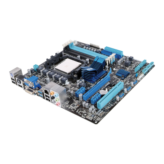
Page 18: Motherboard Overview
Place eight screws into the holes indicated by circles to secure the motherboard to the chassis. DO NOT overtighten the screws! Doing so can damage the motherboard. Place this side towards the rear of the chassis. M4A88T-M/USB3 Chapter 1: Product introduction... -
Page 19: Motherboard Layout
LPT connector (26-1 pin LPT) 1-27 14. USB connectors (10-1 pin USB78, USB910, 1-26 USB1112) MemOK! button 1-28 15. Digital audio connector (4-1 pin SPDIF_OUT) 1-24 DRAM LED 1-29 16. Front panel audio connector (10-1 pin AAFP) 1-21 ASUS M4A88T-M/USB3... -
Page 20: Central Processing Unit (Cpu)
Installing the CPU To install a CPU: Locate the CPU socket on the motherboard. M4A88T-M/USB3 M4A88T-M/USB3 CPU Socket AM3 Press the lever sideways to unlock the Socket lever socket, then lift it up to a 90°-100° angle. Ensure that the socket lever is lifted up to a 90°-100° angle; otherwise, the CPU will not fit in completely. - Page 21 Connect the CPU fan cable to the CPU_FAN connector on the motherboard. CPU_FAN M4A88T-M/USB3 M4A88T-M/USB3 CPU fan connector DO NOT forget to connect the CPU fan connector! Hardware monitoring errors can occur if you fail to plug this connector. ASUS M4A88T-M/USB3...
-
Page 22: Installing The Heatsink And Fan
1.6.2 Installing the heatsink and fan Ensure that you use only AMD-certified heatsink and fan assembly. To install the CPU heatsink and fan: Place the heatsink on top of the installed CPU, ensuring that the heatsink fits properly on the retention module base. •... -
Page 23: System Memory
DDR2 DIMM socket. DDR3 modules are developed for better performance with less power consumption. The figure illustrates the location of the DDR3 DIMM sockets: Channel Sockets Channel A DIMM_A1 and DIMM_A2 Channel B DIMM_B1 and DIMM_B2 M4A88T-M/USB3 M4A88T-M/USB3 240-pin DDR3 DIMM sockets ASUS M4A88T-M/USB3 1-11... -
Page 24: Memory Configurations
OS if you want to install 4GB or more memory on the ® motherboard. • This motherboard does not support DIMMs made up of 256 megabits (Mb) chips or less. M4A88T-M/USB3 Motherboard Qualified Vendors Lists (QVL) DDR3 1866 (O.C.) MHz capability DIMM support Chip Vendor Part No. - Page 25 • G.SKILL F3-10666CL9D-4GBPK 2048MB G.SKILL Heat-Sink Package • • • G.SkiLL F3-10666CL7T-6GBPK 6144MB(Kit of 3) Heat-Sink Package 7-7-7-18 • • • G.SKILL F3-1066CL9T-6GBNQ 6144MB(Kit of 3) Heat-Sink Package 9-9-9-24 • • • (continued on the next page) ASUS M4A88T-M/USB3 1-13...
- Page 26 DDR3 1333MHz capability DIMM support Chip Vendor Part No. Size Chip NO. Brand GEIL DDR3-1333 CL9-9-9-24 1024MB Heat-Sink Package • • • GEIL GV34GB1333C7DC 2048MB Heat-Sink Package 7-7-7-24 • • • GEIL DDR3-1333 CL9-9-9-24 6144MB(Kit of 3) Heat-Sink Package • •...
- Page 27 Dual-channel memory configuration. • C*: Supports two pairs of modules inserted into both the blue and the black slots as two pairs of Dual-channel memory configuration. Visit the ASUS website at www.asus.com for the latest QVL. ASUS M4A88T-M/USB3 1-15...
-
Page 28: Installing A Dimm
1.7.3 Installing a DIMM Unplug the power supply before adding or removing DIMMs or other system components. Failure to do so can cause severe damage to both the motherboard and the components. To install a DIMM: DIMM notch Press the retaining clips outward to unlock a DIMM socket. -
Page 29: Expansion Slots
This motherboard supports PCI Express x1 network cards, SCSI cards, and other cards that comply with the PCI Express specifications. 1.8.5 PCI Express x16 slot This motherboard supports a PCI Express x16 graphics card that complies with the PCI Express specifications. ASUS M4A88T-M/USB3 1-17... -
Page 30: Jumpers
Normal Clear RTC (Default) M4A88T-M/USB3 Clear RTC RAM To erase the RTC RAM: 1. Turn OFF the computer and unplug the power cord. 2. Move the jumper cap from pins 1-2 (default) to pins 2-3. Keep the cap on pins 2-3 for about 5~10 seconds, then move the cap back to pins 1-2. -
Page 31: Connectors
8-channel configurations, the function of this port becomes Front Speaker Out. Microphone port (pink). This port connects to a microphone. Side Speaker Out port (gray). This port connects to the side speakers in the 8-channel audio configuration. ASUS M4A88T-M/USB3 1-19... - Page 32 Refer to the audio configuration table below for the function of the audio ports in the 2, 4, 6, or 8-channel configuration. Audio 2, 4, 6, or 8-channel configuration Headset Port 4-channel 6-channel 8-channel 2-channel Light Blue Line In Line In Line In Line In Lime...
-
Page 33: Internal Connectors
Legacy AC’97 pin definition compliant definition M4A88T-M/USB3 Front panel audio connector • We recommend that you connect a high-definition front panel audio module to this connector to avail of the motherboard high-definition audio capability. • If you want to connect a high definition front panel audio module to this connector, set the Front Panel Select item in the BIOS to [HD Audio]. -
Page 34: Atx Power Connectors
The system may become unstable or may not boot up if the power is inadequate. • If you are uncertain about the minimum power supply requirement for your system, refer to the Recommended Power Supply Wattage Calculator at http://support.asus. com/PowerSupplyCalculator/PSCalculator.aspx?SLanguage=en-us for details. 1-22... - Page 35 • Use the 80-conductor IDE cable for Ultra DMA 133/100 IDE devices. If any device jumper is set as “Cable-Select”, ensure that all other device jumpers have the same setting. PRI_IDE M4A88T-M/USB3 NOTE:Orient the red markings on the IDE ribbon cable to PIN 1. M4A88T-M/USB3 IDE connector ASUS M4A88T-M/USB3 1-23...
-
Page 36: Serial Ata Connectors
This connector is for an additional Sony/Philips Digital Interface (S/PDIF) port. M4A88T-M/USB3 SPDIF_OUT M4A88T-M/USB3 Digital audio connector Ensure that the audio device of Sound playback is VIA High Definition Audio (the name may be different based on the OS). Go to Start > Control Panel > Sounds and Audio Devices >... -
Page 37: System Panel Connector
IDE_LED PWRSW RESET * Requires an ATX power supply M4A88T-M/USB3 System panel connector • System power LED (2-pin PLED) This 2-pin connector is for the system power LED. Connect the chassis power LED cable to this connector. The system power LED lights up when you turn on the system power, and blinks when the system is in sleep mode. - Page 38 The connector is for a serial (COM) port. Connect the serial port module cable to the connector, then install the module to a slot opening at the back of the system chassis. The serial port module is purchased separately. COM1 PIN 1 M4A88T-M/USB3 M4A88T-M/USB3 Serial port (COM1) connector 1-26 Chapter 1: Product introduction...
- Page 39 These are not jumpers! DO NOT place jumper caps on the fan connectors. Only the 4-pin CPU fan supports the ASUS Q-Fan feature. LPT connector (26-1 pin LPT) The LPT (Line Printing Terminal) connector supports devices such as a printer. LPT is standardized as IEEE 1284, which is the parallel port interface on IBM PC-compatible computers.
-
Page 40: Onboard Switches
If the installed DIMMs still fail to boot after the whole tuning process, the DRAM_LED lights continuously. Replace the DIMMs with ones recommended in the Memory QVL (Qualified Vendors Lists) in this user manual or on the ASUS website at www.asus.com. -
Page 41: Onboard Leds
SB_PWR M4A88T-M/USB3 Standby Power Powered Off M4A88T-M/USB3 Onboard Power LED DRAM LED DRAM LED checks the DRAM in sequence during motherboard booting process. If an error is found , the LED next to the error device will continue lighting until the problem is solved. -
Page 42: Software Support
Place the Support DVD into the optical drive. If Autorun is enabled on your computer, the DVD automatically displays the Specials screen which contains the unique feature of ASUS motherboards. Click Drivers, Utilities, Make Disk, Manuals, Contact, and Specials tabs to display their respective menus. -
Page 43: Chapter 2 Bios Information
BIOS in the future. Copy the original motherboard BIOS using the ASUS Update utility. 2.1.1 ASUS Update The ASUS Update is a utility that allows you to manage, save, and update the motherboard BIOS in Windows environment. ®... -
Page 44: Asus Ez Flash 2
Follow the onscreen instructions to complete the updating process. 2.1.2 ASUS EZ Flash 2 The ASUS EZ Flash 2 feature allows you to update the BIOS without using an OS-based utility. Before you start using this utility, download the latest BIOS file from the ASUS website at www.asus.com. -
Page 45: Asus Crashfree Bios 3
2.1.3 ASUS CrashFree BIOS 3 ASUS CrashFree BIOS 3 is an auto recovery tool that allows you to restore the BIOS file when it fails or gets corrupted during the updating process. You can restore a corrupted BIOS file using the motherboard support DVD or a USB flash drive that contains the BIOS file. -
Page 46: Bios Setup Program
• The BIOS setup screens in this chapter are for reference only. They may not exactly match what you see on your screen. • Visit the ASUS website at www.asus.com to download the latest BIOS file for this motherboard. Chapter 2: BIOS information... -
Page 47: Bios Menu Screen
2.2.1 BIOS menu screen Menu items Configuration fields General help Menu bar M4A88T-M/USB3 BIOS Setup Version 0306 Main Advanced Power Boot Tools Exit Main Settings Use [ENTER], [TAB] System Time [19:34:30] or [SHIFT-TAB] to System Date [Thu 01/10/2002] select a field. -
Page 48: Menu Items
<Enter> to display a list of options. Refer to 2.2.7 Pop-up window. 2.2.7 Pop-up window Select a menu item then press <Enter> M4A88T-M/USB3 BIOS Setup Version 0306 Advanced to display a pop-up window with the CPU Configuration... -
Page 49: Main Menu
When you enter the BIOS Setup program, the Main menu screen appears, giving you an overview of the basic system information. Refer to section 2.2.1 BIOS menu screen for information on the menu screen items and how to navigate through them. M4A88T-M/USB3 BIOS Setup Version 0306 Main Advanced... -
Page 50: Sata Configuration
LBA/Large Mode [Auto] Enables or disables the LBA mode. Setting this item to [Auto] enables the LBA mode if the device supports this mode, and if the device was not previously formatted with LBA mode disabled. Configuration options: [Disabled] [Auto] Block (Multi-Sector Transfer) M [Auto] Enables or disables data multi-sectors transfers. -
Page 51: System Information
The Advanced menu items allow you to change the settings for the CPU and other system devices. Take caution when changing the settings of the Advanced menu items. Incorrect field values can cause the system to malfunction. M4A88T-M/USB3 BIOS Setup Version 0306 Main Advanced... - Page 52 The following item only appears when you set CPU OverClocking to [Manual]. CPU/HT Reference Clock (MHz) [200] Sets the CPU/HT Reference Clock. Configuration options: [Min.=200] [Max.=550] The following item only appears when you set CPU Overclocking to [Overclock Profile]. Overclock Options [Auto] Selects the overclocking profile.
- Page 53 Configuration options: [Auto] [3 CLK] ~ [17 CLK] tWRRD [Auto] Configuration options: [Auto] [2 CLK] ~ [10 CLK] tWTR [Auto] Configuration options: [Auto] [4 CLK] ~ [7 CLK] tWRWR [Auto] Configuration options: [Auto] [3 CLK] ~ [10 CLK] ASUS M4A88T-M/USB3 2-11...
-
Page 54: Cpu Configuration
tRDRD [Auto] Configuration options: [Auto] [3 CLK] ~ [10 CLK] tRFC0/1/2/3 [Auto] Configuration options: [Auto] [90ns] [110ns] [160ns] [300ns] [350ns] Memory Over Voltage [Auto] Sets the memory over voltage. The value ranges from 1.2000V to 2.4450V with a 0.0150V increment. Use the <+> / <-> keys to adjust the value. Chipset Over Voltage [Auto] Sets the chipset over voltage. - Page 55 These items only appear when you set Advanced Clock Calibration to [Per Core] and allow you to set the overclocking percentage for each process core separately. Configuration options: [0%] [+2%] [+4%] [+6%] [+8%] [+10%] [+12%] [-2%] [-4%] [-6%] [-8%] [-10%] [-12%] ASUS M4A88T-M/USB3 2-13...
-
Page 56: Chipset
2.4.3 Chipset NorthBridge Configuration Memory Configuration Bank Interleaving [Auto] Allows you to enable the bank memory interleaving. Configuration options: [Disabled] [Auto] Channel Interleaving [XOR of Address bits [20:16, 6]] Allows you to enable the channel memory interleaving. Configuration options: [Disabled] [Address bits 6] [Address bits 12] [XOR of Address bits [20:16, 6]] [XOR of Address bits [20:16, 9]] Enable Clock to All DIMMs [Disabled] Enables unused Clocks to DIMMs even though memory slots are not populated. -
Page 57: Onboard Device Configuration
Enables or disables the onboard LAN controller. Configuration options: [Enabled] [Disabled] OnBoard LAN Boot ROM [Disabled] Enables or disables the Onboard LAN Boot ROM. Configuration options: [Disabled] [Enabled] USB3.0 Controller [Enabled] Enables or disables the USB 3.0 controller. Configuration options: [Enabled] [Disabled] ASUS M4A88T-M/USB3 2-15... -
Page 58: Pcipnp
2.4.5 PCIPnP The PCI PnP menu items allow you to change the advanced settings for PCI/PnP devices. The menu includes setting IRQ and DMA channel resources for either PCI/PnP or legacy ISA devices and setting the memory size block for legacy ISA devices. Take caution when changing the settings of the PCI PnP menu items. -
Page 59: Power Menu
The Power menu items allow you to change the settings for the Advanced Configuration and Power Interface (ACPI) and the Advanced Power Management (APM). Select an item then press <Enter> to display the configuration options. M4A88T-M/USB3 BIOS Setup Version 0306 Main... -
Page 60: Hw Monitor Configuration
Select [Ignored] if you do not want the detected voltage to be displayed. Smart Q-FAN Function [Enabled] Enables or disables the ASUS Q-Fan feature that smartly adjusts the CPU fan speed for more efficient system operation. Configuration options: [Disabled] [Enabled] Fan Auto Mode Start Voltage [5.0V]... -
Page 61: Boot Menu
Configuration options: [Removable Dev.] [Hard Drive] [ATAPI CD-ROM] [Disabled] • To select the boot device during system startup, press <F8> when ASUS Logo appears. • To access Windows OS in Safe Mode, do any of the following: ®... -
Page 62: Security
AddOn ROM Display Mode [Force BIOS] Sets the display mode for option ROM. Configuration options: [Force BIOS] [Keep Current] Bootup Num-Lock [On] Selects the power-on state for the NumLock. Configuration options: [Off] [On] Wait for ‘F1’ If Error [Enabled] When this item is set to [Enabled], the system waits for the F1 key to be pressed when error occurs. -
Page 63: Tools Menu
(C)Copyright 1985-2010, American Megatrends, Inc. 2.7.1 ASUS EZ Flash 2 Allows you to run ASUS EZ Flash 2. When you press <Enter>, a confirmation message appears. Use the left/right arrow key to select between [Yes] or [No], then press <Enter> to confirm your choice. -
Page 64: Express Gate
2.7.2 Express Gate [Auto] Enables or disables the ASUS Express Gate feature. ASUS Express Gate is a unique instant-on environment that provides quick access to the Internet and Skype. Configuration options: [Enabled] [Disabled] [Auto] Enter OS Timer [10 Seconds] Sets countdown duration that the system waits at the Express Gate’s first screen before starting Windows or other installed OS. -
Page 65: Ai Net 2
BIOS version. • Only the CMO file can be loaded. 2.7.4 AI NET 2 Check Realtek LAN cable [Disabled] Enables or disables checking of the Realtek LAN cable during the Power-On Self-Test (POST). Configuration options: [Disabled] [Enabled] ASUS M4A88T-M/USB3 2-23... -
Page 66: Exit Menu
Exit menu The Exit menu items allow you to load the optimal or failsafe default values for the BIOS items, and save or discard your changes to the BIOS items. M4A88T-M/USB3 BIOS Setup Version 0306 Main Advanced Power Boot Tools... -
Page 67: Asus Contact Information
+1-510-739-3777 +1-510-608-4555 Web site usa.asus.com Technical Support Telephone +1-812-282-2787 Support fax +1-812-284-0883 Online support support.asus.com ASUS Computer GmbH (Germany and Austria) Address Harkort Str. 21-23, D-40880 Ratingen, Germany +49-2102-959911 Web site www.asus.de Online contact www.asus.de/sales Technical Support Telephone (Component) +49-1805-010923*...
Need help?
Do you have a question about the M4A88T-M/USB3 and is the answer not in the manual?
Questions and answers