Table of Contents
Advertisement
Advertisement
Table of Contents

Related Manuals for Asus Prime J4005I-C


Summary of Contents for Asus Prime J4005I-C
- Page 1 PRIME J4005I-C...
- Page 2 Product warranty or service will not be extended if: (1) the product is repaired, modified or altered, unless such repair, modification of alteration is authorized in writing by ASUS; or (2) the serial number of the product is defaced or missing.
-
Page 3: Table Of Contents
Contents Safety information ...................... iv About this guide ......................iv Package contents ....................... vi PRIME J4005I-C specifications summary ..............vi Chapter 1: Product introduction Motherboard overview ..................... 1-1 Central Processing Unit (CPU)................1-7 System memory ....................... 1-7 Chapter 2: BIOS information BIOS setup program .................... -
Page 4: Safety Information
Safety information Electrical safety • To prevent electrical shock hazard, disconnect the power cable from the electrical outlet before relocating the system. • When adding or removing devices to or from the system, ensure that the power cables for the devices are unplugged before the signal cables are connected. If possible, disconnect all power cables from the existing system before you add a device. - Page 5 Refer to the following sources for additional information and for product and software updates. ASUS websites The ASUS website provides updated information on ASUS hardware and software products. Refer to the ASUS contact information. Optional documentation Your product package may include optional documentation, such as warranty flyers, that may have been added by your dealer.
-
Page 6: Package Contents
2 x U-DIMM, Max. 8GB*, DDR4 2400/2133 MHz, non-ECC, un-buffered memory** Dual-channel memory architecture * We recommend that you use 8GB or less memory modules. ** Refer to www.asus.com for the Memory QVL (Qualified Vendors List). Graphics Integrated Graphics Processor - Intel UHD Graphics 600 support ®... - Page 7 ASUS 5X PROTECTION II - ASUS LANGuard - Surge-protected networking - ASUS Overvoltage Protection - World-class circuit-protecting power design - ASUS Enhanced DRAM Overcurrent Protection - Short circuit damage prevention - Stainless Steel Back I/O - 3X corrosion-resistance for greater durability...
- Page 8 BIOS features 128 Mb Flash ROM, UEFI AMI BIOS, PnP, DMI2.0, WfM2.0, SM BIOS 3.0, ACPI 6.0, Multi-language BIOS, ASUS EZ Flash 3, My Favorites, Quick Note, Last Modified log, F12 PrintScreen, F3 Shortcut functions and ASUS DRAM SPD (Serial Presence Detect) memory information,...
-
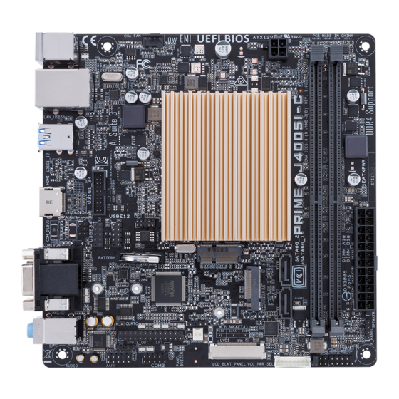
Page 9: Motherboard Overview
U31G1_12 Intel ® J4005 Place this side towards the rear of the HDMI chassis USBE34 USBE12 128Mb BIOS M.2 (WIFI) Super 2280 2260 CHASSIS AUDIO PANEL_SW VCC_PWR_SEL 887-VD2 LVDS COM2 LCD_BLKT_PANEL F_PANEL AAFP 17 16 15 Scan the QR code to get the detailed pin definitions. ASUS PRIME J4005I-C... - Page 10 M.2 socket, E Key This socket allows you to install E key and type 2230 Wi-Fi/BT devices ATX power connectors (24-pin EATXPWR, 4-pin ATX12V) These connectors are for ATX power supply plugs. The power supply plugs are designed to fit these connectors in only one orientation. Find the proper orientation and push down firmly until the connectors completely fit. • For a fully configured system, we recommend that you use a power supply unit (PSU) that complies with ATX 12 V Specification 2.0 (or later version) and provides a minimum power of 350 W. • DO NOT forget to connect the 4-pin ATX +12V power plug. Otherwise, the system will not boot up. • We recommend that you use a PSU with higher power output when configuring a system with more power-consuming devices or when you intend to install additional devices. The system may become unstable or may not boot up if the power is inadequate. • If you are uncertain about the minimum power supply requirement for your system, refer to the Recommended Power Supply Wattage Calculator at http://support. asus.com.cn/PowerSupply.aspx?SLanguage=en for details. M.2 socket 3 M.2(SOCKET3) This socket allows you to install M.2 (NGFF) SSD modules. This socket supports M Key and type 2260/2280 storage devices. Chapter 1: Product introduction...
- Page 11 Serial ATA 6.0Gb/s connectors (7-pin SATA6G_1~2) ® These connectors connect to Serial ATA 6.0 Gb/s hard disk drives via Serial ATA 6.0 Gb/s signal cables. LVDS connector (40-pin LVDS) This connector is for an LCD monitor that supports Low-voltage Differential Signaling (LVDS) interface. Panel switch (2-pin PANEL_SW) This 2-pin header is for connecting a monitor switch that can turn off the LCD panel display backlight. Chassis intrusion connector (4-1 pin CHASSIS) This connector is for a chassis-mounted intrusion detection sensor or switch. Connect one end of the chassis intrusion sensor or switch cable to this connector. The chassis intrusion sensor or switch sends a high-level signal to this connector when a chassis component is removed or replaced. The signal is then generated as a chassis intrusion event. The chassis intrusion detection feature is disabled by default. To enable it, set the Chassis Intrude Detect Support item in the BIOS to [On]. ASUS PRIME J4005I-C...
- Page 12 Serial port connector (10-1 pin COM2) This connector is for a serial (COM) port. Connect the serial port module cable to this connector, then install the module to a slot opening at the back of the system chassis. Digital audio connector (4-1 pin SPDIF_OUT) This connector is for an additional Sony/Philips Digital Interface (S/PDIF) port. Connect the S/PDIF Out module cable to this connector, then install the module to a slot opening at the back of the system chassis. PIN 1 SPDIF_OUT Front panel audio connector (10-1 pin AAFP) This connector is for a chassis-mounted front panel audio I/O module that supports either HD Audio or legacy AC`97 audio standard. Connect one end of the front panel audio I/O module cable to this connector. • We recommend that you connect a high-definition front panel audio module to this connector to avail of the motherboard’s high-definition audio capability. • If you want to connect a high-definition front panel audio module to this connector, set the Front Panel Type item in the BIOS setup to [HD Audio]. If you want to connect an AC’97 front panel audio module to this connector, set the item to [AC97]. By default, this connector is set to [HD Audio]. LPT connector (26-1 pin LPT) The LPT (Line Printing Terminal) connector supports devices such as a printer.
- Page 13 LAN port LED indications LAN port Activity/Link LED Speed LED Status Description Status Description No link 10Mbps connection Orange Linked ORANGE 100Mbps connection Orange (Blinking) Data activity GREEN 1Gbps connection Orange (Blinking Ready to wake up then steady) from S5 mode Video Graphics Adapter (VGA) port. This 15-pin port is for a VGA monitor or other VGA-compatible devices. Line In port (light blue). This port connects to the tape, CD, DVD player, or other audio sources. ASUS PRIME J4005I-C...
- Page 14 Line Out port (lime). This port connects to a headphone or a speaker. In the 4.1, 5.1 and 7.1-channel configurations, the function of this port becomes Front Speaker Out. Microphone port (pink). This port connects to a microphone. Refer to the audio configuration table for the function of the audio ports in 2.1, 4.1, 5.1, or 7.1-channel configuration. Audio 2.1, 4.1, 5.1, or 7.1-channel configuration Headset Port 4.1-channel 5.1-channel 7.1-channel 2.1-channel Light Blue (Rear Line In Rear Speaker Out Rear Speaker Out Rear Speaker Out panel) Lime (Rear panel) Line Out Front Speaker Out Front Speaker Out Front Speaker Out Pink (Rear panel) Mic In Mic In Bass/Center Bass/Center Lime (Front panel) Side Speaker Out To configure a 7.1-channel audio output: Use a chassis with HD audio module in the front panel to support a 7.1-channel audio...
-
Page 15: Central Processing Unit (Cpu)
Central Processing Unit (CPU) This motherboard comes with an onboard Intel Celeron Dual-core processor J4005. ® ® Onboard Intel Celeron ® ® Dual-core Processor J4005 PRIME J4005I-C CPU System memory Overview This motherboard comes with two Double Data Rate 4 (DDR4) Dual Inline Memory Module (DIMM) sockets. The figure illustrates the location of the DDR4 DIMM sockets: Channel Sockets DIMM_A1 Channel A DIMM_A1 DIMM_B1 Channel B DIMM_B1 • You may install varying memory sizes in Channel A and Channel B. The system maps the total size of the lower-sized channel for the dual-channel configuration. Any excess memory from the higher-sized channel is then mapped for single-channel operation. • Always install the DIMMS with the same CAS Latency. For an optimum compatibility, we recommend that you install memory modules of the same version or data code (D/C) from the same vendor. Check with the vendor to get the correct memory... - Page 16 Installing a DIMM To remove a DIMM Chapter 1: Product introduction...
-
Page 17: Chapter 2: Bios Information
To enter BIOS Setup after POST: • Press <Ctrl>+<Alt>+<Del> simultaneously. • Press the reset button on the system chassis. • Press the power button to turn the system off then back on. Do this option only if you failed to enter BIOS Setup using the first two options. Using the power button, reset button, or the <Ctrl>+<Alt>+<Del> keys to force reset from a running operating system can cause damage to your data or system. We recommend you always shut down the system properly from the operating system. • The BIOS setup screens shown in this section are for reference purposes only, and may not exactly match what you see on your screen. • Visit the ASUS website at www.asus.com to download the latest BIOS file for this motherboard. • If the system becomes unstable after changing any BIOS setting, load the default settings to ensure system compatibility and stability. Select the Load Optimized Defaults item under the Exit menu or press hotkey F5. • If the system fails to boot after changing any BIOS setting, try to clear the CMOS and reset the motherboard to the default value. See section Motherboard overview for information on how to erase the RTC RAM. BIOS menu screen The BIOS setup program can be used under two modes: EZ Mode and Advanced Mode. Press <F7> to change between the two modes. ASUS PRIME J4005I-C... -
Page 18: Ez Mode
EZ Mode By default, the EZ Mode screen appears when you enter the BIOS setup program. The EZ Mode provides you an overview of the basic system information, and allows you to select the display language, system performance mode, fan profile and boot device priority. To access the Advanced Mode, click Advanced Mode(F7) or press <F7>. The default screen for entering the BIOS setup program can be changed. Go to the Setup Mode item under the Boot menu. Displays the system properties Displays the CPU/motherboard of the selected mode. temperature, CPU voltage output, CPU/chassis fan speed, and SATA Selects the display language of information the BIOS setup program Displays the Advanced Displays the CPU Fan’s mode menus... -
Page 19: Advanced Mode
Q-Fan control Hot Keys MyFavorite Language Menu bar General help Sub-menu item Search on Last modified Pop-up Menu items FAQs settings window Goes back Configuration fields to EZ Mode Displays the CPU temperature, CPU and memory voltage output ASUS PRIME J4005I-C... -
Page 20: Exit Menu
Exit menu The Exit menu items allow you to load the optimal default values for the BIOS items, and save or discard your changes to the BIOS items. Load Optimized Defaults This option allows you to load the default values for each of the parameters on the Setup menus. When you select this option or if you press <F5>, a confirmation window appears. Select OK to load the default values. Save Changes & Reset Once you are finished making your selections, choose this option from the Exit menu to ensure the values you selected are saved. When you select this option or if you press <F10>, a confirmation window appears. Select OK to save changes and exit. Discard Changes & Exit This option allows you to exit the Setup program without saving your changes. When you select this option or if you press <Esc>, a confirmation window appears. Select OK to discard changes and exit. Launch EFI Shell from USB drives This option allows you to attempt to launch the EFI Shell application (shellx64.efi) from one of the available USB devices. Chapter 2: BIOS Information... -
Page 21: Appendix
: (1) l’appareil ne doit pas produire de brouillage, et (2) l’utilisateur de l’appareil doit accepter tout brouillage radioélectrique subi, même si le brouillage est susceptible d’en compromettre le fonctionnement. CAN ICES-3(B)/NMB-3(B) ASUS PRIME J4005I-C... - Page 22 ASUS Recycling/Takeback Services ASUS recycling and takeback programs come from our commitment to the highest standards for protecting our environment. We believe in providing solutions for you to be able to responsibly recycle our products, batteries, other components as well as the packaging materials.
- Page 23 Slovensky Spoločnosť ASUSTeK Computer Inc. týmto vyhlasuje, že toto Cijeli tekst EU izjave o sukladnosti dostupan je na: www.asus.com/support zariadenie vyhovuje základným požiadavkám a ostatým príslušným ustanoveniam príslušných smerníc. Celý text vyhlásenia o zhode pre štáty EÚ...
-
Page 24: Asus Contact Information
+1-510-739-3777 +1-510-608-4555 Web site http://www.asus.com/us/ Technical Support Support fax +1-812-284-0883 Telephone +1-812-282-2787 Online support http://qr.asus.com/techserv ASUS COMPUTER GmbH (Germany and Austria) Address Harkort Str. 21-23, 40880 Ratingen, Germany +49-2102-959931 Web site http://www.asus.com/de Online contact http://eu-rma.asus.com/sales Technical Support Telephone +49-2102-5789555 Support Fax... - Page 25 CA 94539. Phone/Fax No: (510)739-3777/(510)608-4555 hereby declares that the product Product Name : Motherboard Model Number : PRIME J4005I-C Conforms to the following specifications: FCC Part 15, Subpart B, Unintentional Radiators Supplementary Information: This device complies with part 15 of the FCC Rules. Operation is subject to the...
Need help?
Do you have a question about the Prime J4005I-C and is the answer not in the manual?
Questions and answers