Table of Contents
Advertisement
Advertisement
Chapters
Table of Contents

Related Manuals for Asus Pro WS C422-ACE


Summary of Contents for Asus Pro WS C422-ACE
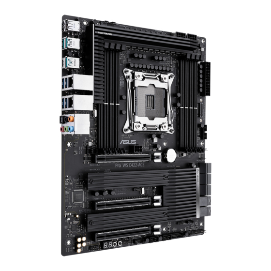
- Page 1 Pro WS C422-ACE...
- Page 2 Product warranty or service will not be extended if: (1) the product is repaired, modified or altered, unless such repair, modification of alteration is authorized in writing by ASUS; or (2) the serial number of the product is defaced or missing.
-
Page 3: Table Of Contents
Contents Safety information ...................... iv About this guide ......................iv Package contents ....................... vi ASUS Pro WS C422-ACE specifications summary ..........vi Chapter 1: Product Introduction Before you proceed ................... 1-1 Motherboard overview ................1-1 Central Processing Unit (CPU) ............... 1-11 System memory .................. -
Page 4: Safety Information
Safety information Electrical safety • To prevent electrical shock hazard, disconnect the power cable from the electrical outlet before relocating the system. • When adding or removing devices to or from the system, ensure that the power cables for the devices are unplugged before the signal cables are connected. If possible, disconnect all power cables from the existing system before you add a device. - Page 5 Refer to the following sources for additional information and for product and software updates. ASUS website The ASUS website (www.asus.com) provides updated information on ASUS hardware and software products. Optional documentation Your product package may include optional documentation, such as warranty flyers, that may have been added by your dealer.
-
Page 6: Package Contents
- Quad channel memory architecture * Memory capacity supported depends on both CPU installed and Memory. ** Refer to www.asus.com for the Memory QVL (Qualified Vendors List). 48-Lane CPU(CLX-W, SKL-W) 2 x PCI Express 3.0/2.0 x16 slots (dual at x16/x16 mode) Expansion 1 x PCI Express 3.0/2.0 x16 slots (max. - Page 7 ASUS Pro WS C422-ACE specifications summary Intel Xeon™ W-Series Processors support with RAID 0, 1, 5, 10 and Intel ® ® Virtual RAID (VROC) Support 1 x M.2_2 Socket 3 with M key, type 2242/2260/2280/22110 storage devices support (PCIE 3.0 x4 mode) 1 x M.2_3 Socket 3 with M key, type 2242/2260/2280/22110 storage devices support...
- Page 8 - ASUS Q-Code - ASUS Q-Slot ASUS SafeSlot - Protect your graphics card Investment ASUS 5X Protection III - ASUS LANGuard: Protects against LAN surges, lightning strikes and static- electricity discharges! - ASUS Overvoltage Protection: World-class circuit-protecting power design Special...
- Page 9 1 x Q_Code 128 Mb Flash ROM, UEFI AMI BIOS, PnP, SM BIOS 3.2, ACPI 6.0, Multi- language BIOS, ASUS EZ Flash 3, CrashFree BIOS 3, F1 General Help, F2 Previous Values, F3 MyFavorite, F5 Optimized Default, F6 QFan Control, F7 EZ...
- Page 10 ASUS Pro WS C422-ACE specifications summary WfM 2.0, DMI 3.0, WOL by PME, PXE Manageability Drivers ASUS Utilities Support DVD EZ Update Anti-virus software (OEM version) Windows 10 64-bit OS Support ® ATX Form Factor, 12”x 9.6” (30.5cm x 24.4cm) Form factor Specifications are subject to change without notice.
-
Page 11: Chapter 1: Product Introduction
Failure to do so may cause severe damage to the motherboard, peripherals, or components. Motherboard overview Place this side towards the rear of the chassis Unplug the power cord before installing or removing the motherboard. Failure to do so can cause you physical injury and damage motherboard components. ASUS Pro WS C422-ACE... - Page 12 1.2.1 Layout contents Connectors/Jumpers/Slots Page DDR4 DIMM slots CPU, CPU optional, chassis, and AIO pump fan connectors (4-pin CPU_FAN, 4-pin CPU_OPT, 4-pin CHA_FAN1~3, 4-pin AIO_PUMP FAN) Intel LGA2066 CPU socket ® ATX power connectors (24-pin EATXPWR, 8-pin EATX12V_1-2, 6-pin EATX12V3) M.2 sockets (M.2_1-3(SOCKET3)) USB 3.2 Gen 1 connector (20-1 pin U32G1_34; 20-1 pin U32G1_12) SATA 6Gb/s connector (7-pin SATA6G_1-6) Mini-SAS HD connector (U.2_1-2) VROC_HW_KEY connector (4-pin VROC_KEY) 10. System panel connector (20-3 pin PANEL) 11. USB 2.0 connector (10-1 pin USB1112; USB910) 12. Clear RTC RAM (2-pin CLRTC) 13. Thermal Sensor connector (2-pin T_SENSOR) 14. Node connector (12-1 pin NODE) 15. TPM connector (14-1 pin TPM) 16. USB BIOS Flashback button 17. Power button 18. Q-Code LED 19. Front panel audio connector (10-1 pin AAFP) 20. PCI Express 3.0/2.0 x16 slots DDR4 DIMM slots Install 2 GB, 4 GB, 8 GB, 16 GB, and 32 GB DDR4 DIMMs into these DIMM sockets.
-
Page 13: Intel ® Lga2066 Cpu Socket
+3 Volts +3 Volts PIN 1 • The 8-pin Power Plug LED lights up to indicate that the 8-pin power plug is not connected. • For a fully configured system, we recommend that you use a power supply unit (PSU) that complies with ATX 12 V Specification 2.0 (or later version) and provides a minimum power of 350 W. This PSU type has 24-pin and 8-pin power plugs. • We recommend that you use a PSU with higher power output when configuring a system with more power-consuming devices or when you intend to install additional devices. The system may become unstable or may not boot up if the power is inadequate. M.2 sockets (M.2_1-3(SOCKET3)) M.2_1(SOCKET3) M.2_2-3(SOCKET3) These sockets allow you to install M.2 (NGFF) SSD modules. • The M.2_1 socket supports vertical M Key and 2242/2260/2280/22110 storage devices (both SATA & PCIE 3.0 x4 mode from PCH). • The M.2_2 and M.2_3 socket supports M Key and 2242/2260/2280/22110 storage devices (PCIe 3.0 x4 mode from CPU). The M.2 SSD module is purchased separately. ASUS Pro WS C422-ACE... -
Page 14: Usb 3.2 Gen 1 Connector (20-1 Pin U32G1_34; 20-1 Pin U32G1_12)
USB 3.2 Gen 1 connector (20-1 pin U32G1_34; U32G1 20-1 pin U32G1_12) PIN 1 USB3+5V Connect a USB 3.2 Gen 1 module to any of these USB3+5V IntA_P1_SSRX- IntA_P2_SSRX- IntA_P1_SSRX+ connectors for additional USB 3.2 Gen 1 front or rear IntA_P2_SSRX+ IntA_P1_SSTX- panel ports. These connectors comply with USB 3.2 IntA_P2_SSTX- IntA_P1_SSTX+ IntA_P2_SSTX+ IntA_P1_D- Gen 1 specifications and provides faster data transfer IntA_P2_D- IntA_P1_D+ IntA_P2_D+ speeds of up to 5 Gbps, faster charging time for USB- chargeable devices, optimized power efficiency, and backward compatibility with USB 2.0 SATA 6Gb/s connector (7-pin SATA6G_1-6) SATA6G These connectors connect to Serial ATA 6.0 Gb/s hard disk drives via Serial ATA 6.0 Gb/s signal cables. -
Page 15: System Panel Connector (20-3 Pin Panel)
This connector is for a chassis-mounted intrusion detection sensor or switch. USB 2.0 connector (10-1 pin USB1112; USB910) USB910 USB1112 Connect a USB module cable to this connector, then install the module to a slot opening at the back of the system chassis. This USB connectors comply with USB 2.0 specifications and supports up to 480Mbps connection speed. PIN 1 PIN 1 ASUS Pro WS C422-ACE... -
Page 16: Clear Rtc Ram (2-Pin Clrtc)
Thermal Sensor connector (2-pin T_SENSOR) The Thermal Sensor connector allows you to connect a sensor to monitor the temperature of the devices and the critical components inside the motherboard. Connect the thermal sensor and place it on the device or the motherboard’s component to detect its temperature. Node connector (12-1 pin NODE) The Node connector allows you to connect Node compatible devices. Visit www.asus.com for more information about the devices and the latest compatibility list. TPM connector (14-1 pin TPM) This connector supports a Trusted Platform Module (TPM) system, which securely store keys, digital certificates, passwords and data. A TPM system also helps enhance network security, protect digital identities, and ensures platform integrity. Chapter 1: Product Introduction... - Page 17 Flashback function is enabled. Power button Press the Power button to power up the system, or put the system into sleep or soft-off mode (depending on the operating system settings). The PWR_LED near the button also lights up when the system is plugged to a power source indicating that you should shut down the system and unplug the power cable before removing or installing any motherboard component. Q-Code LED The Q-Code LED design provides you with a 2-digit error code that displays the system status. • The Q-Code LED provides the most probable cause of an error code as a starting point for troubleshooting. The actual cause may vary from case to case. • Please refer to the Q-Code table in the Appendix section for more details. ASUS Pro WS C422-ACE...
-
Page 18: Front Panel Audio Connector (10-1 Pin Aafp)
Front panel audio connector (10-1 pin AAFP) This connector is for a chassis-mounted front panel audio I/O module that supports HD Audio standard. Connect one end of the front panel audio I/O module AAFP cable to this connector. HD-audio-compliant pin definition PCI Express 3.0/2.0 x16 slots This motherboard supports three PCI Express 3.0/2.0 x16 graphic cards that comply with the PCI Express specifications. Actual PCI Express speeds varies per BIOS settings. PCI Express operating mode VGA configuration PCIe 3.0 x16_1 PCIe 3.0 x16_2 PCIe 3.0 x16_3 Single VGA/PCIe card... - Page 19 1.2.2 Rear panel connectors USB 2.0 ports These four 4-pin Universal Serial Bus (USB) ports are for USB 2.0/1.1 devices. USB 3.2 Gen 2 Type-A ports. These 9-pin Universal Serial Bus 3.2 (USB 3.2) ports are for USB 3.2 Gen 2 devices. • USB 3.2 Gen 1/Gen 2 devices can only be used as data storage only. • We strongly recommend that you connect your devices to ports with matching data transfer rate. Please connect your USB 3.2 Gen 1 devices to USB 3.2 Gen 1 ports and your USB 3.2 Gen 2 devices to USB 3.2 Gen 2 ports for faster and better performance for your devices. USB 3.2 Gen 2 Type-A port. This 9-pin Universal Serial Bus 3.2 (USB 3.2) port is for USB 3.2 Gen 2 devices. • USB 3.2 Gen 1/Gen 2 devices can only be used as data storage only. • We strongly recommend that you connect your devices to ports with matching data transfer rate. Please connect your USB 3.2 Gen 1 devices to USB 3.2 Gen 1 ports and your USB 3.2 Gen 2 devices to USB 3.2 Gen 2 ports for faster and better performance for your devices. ASUS Pro WS C422-ACE...
- Page 20 LAN (RJ-45) port. These ports allow Gigabit connection to a Local Area Network (LAN) through a network hub. LAN port LED indications Activity/Link LED Speed LED ACT/LINK SPEED Status Description Status Description No link 10Mbps connection Orange Linked ORANGE 100Mbps connection Orange (Blinking) Data activity GREEN 1Gbps connection Orange (Blinking Ready to wake Wake up LAN port then steady) from S5 mode USB 3.2 Gen 2 Type-C™ port. This 24-pin Universal Serial Bus (USB) port is for USB (Type C) devices.
-
Page 21: Central Processing Unit (Cpu)
Unplug all power cables before installing the CPU. Ensure that you install the correct CPU designed for LGA2066 socket only. • Ensure that all power cables are unplugged before installing the CPU. • Upon purchase of the motherboard, ensure that the PnP cap is on the socket and the socket contacts are not bent. Contact your retailer immediately if the PnP cap is missing, or if you see any damage to the PnP cap/socket contacts/motherboard components. ASUS will shoulder the cost of repair only if the damage is shipment/ transit-related. • Keep the cap after installing the motherboard. ASUS will process Return Merchandise Authorization (RMA) requests only if the motherboard comes with the cap on the LGA2066 socket. • The product warranty does not cover damage to the socket contacts resulting from incorrect CPU installation/removal, or misplacement/loss/incorrect removal of the PnP cap. Installing the CPU ASUS Pro WS C422-ACE 1-11... - Page 22 Triangle mark Triangle mark Apply the Thermal Interface Material to the CPU heatsink and CPU before you install the heatsink and fan if necessary. 1-12 Chapter 1: Product Introduction...
-
Page 23: System Memory
System memory Overview The motherboard comes with eight DDR4 (Double Data Rate 4) Dual Inline Memory Modules (DIMM) slots. The figure illustrates the location of the DDR4 DIMM sockets: Recommended memory configurations • The default memory operation frequency is dependent on its Serial Presence Detect (SPD), which is the standard way of accessing information from a memory module. Under the default state, some memory modules for overclocking may operate at a lower frequency than the vendor-marked value. • For system stability, use a more efficient memory cooling system to support a full memory load (8 DIMMs) or overclocking condition. • Always install the DIMMS with the same CAS Latency. For an optimum compatibility, we recommend that you install memory modules of the same version or data code (D/C) from the same vendor. Check with the vendor to get the correct memory modules. • Refer to www.asus.com for the latest Memory QVL (Qualified Vendors List) ASUS Pro WS C422-ACE 1-13... - Page 24 Installing a DIMM To remove a DIMM 1-14 Chapter 1: Product Introduction...
-
Page 25: Chapter 2: Bios Information
Managing and updating your BIOS Save a copy of the original motherboard BIOS file to a USB flash disk in case you need to restore the BIOS in the future. Copy the original motherboard BIOS using the ASUS Update utility. - Page 26 2.1.2 ASUS EZ Flash 3 The ASUS EZ Flash 3 allows you to download and update to the latest BIOS through the Internet without having to use a bootable floppy disk or an OS‑based utility. • Ensure to load the BIOS default settings to ensure system compatibility and stability.
- Page 27 2.1.3 ASUS CrashFree BIOS 3 utility The ASUS CrashFree BIOS 3 is an auto recovery tool that allows you to restore the BIOS file when it fails or gets corrupted during the updating process. You can restore a corrupted BIOS file using the motherboard support DVD or a USB flash drive that contains the updated BIOS file.
-
Page 28: Bios Setup Program
The BIOS setup screens shown in this section are for reference purposes only, and may not exactly match what you see on your screen. • Visit the ASUS website at www.asus.com to download the latest BIOS file for this motherboard. •... - Page 29 Click to go to Advanced mode Loads optimized Search on the FAQ default settings Click to display boot devices Selects the boot device priority The boot device options vary depending on the devices you installed to the system. ASUS Pro WS C422-ACE 2‑5...
- Page 30 2.2.2 Advanced Mode The Advanced Mode provides advanced options for experienced end‑users to configure the BIOS settings. The figure below shows an example of the Advanced Mode. Refer to the following sections for the detailed configurations. To access the EZ Mode, click EzMode(F7) or press <F7>. Configuration fields Search(F9) Menu bar...
- Page 31 This button above the menu bar displays the current settings of your fans. Use this button to manually tweak the fans to your desired settings. Search (F9) This button allows you to search for BIOS items by entering its name, enter the item name to find the related item listing. ASUS Pro WS C422-ACE 2‑7...
- Page 32 Move your mouse over this button to show a QR code, scan this QR code on your mobile device to connect to the BIOS FAQ web page of the ASUS support website. You can also scan the following QR code:...
-
Page 33: Exit Menu
<Esc>, a confirmation window appears. Select OK to discard changes and exit. Launch EFI Shell from USB drives This option allows you to attempt to launch the EFI Shell application (shellx64.efi) from one of the available USB devices. ASUS Pro WS C422-ACE... - Page 34 2‑10 Chapter 2: BIOS Information...
-
Page 35: Appendix
CPU self test failed or possible CPU cache error CPU micro-code is not found or micro-code update is failed Internal CPU error Reset PPI is not available Reserved for future AMI error codes 5C – 5F (continued on the next page) ASUS Pro WS C422-ACE... -
Page 36: Q-Code Table
Q-Code table Code Description S3 Resume is stared (S3 Resume PPI is called by the DXE IPL) S3 Boot Script execution Video repost OS S3 wake vector call Reserved for future AMI progress codes E4 – E7 S3 Resume Failed S3 Resume PPI not Found S3 Resume Boot Script Error S3 OS Wake Error... - Page 37 Reserved for ASL (see ASL Status Codes section below) Ready To Boot event Legacy Boot event Exit Boot Services event Runtime Set Virtual Address MAP Begin Runtime Set Virtual Address MAP End Legacy Option ROM Initialization System Reset (continued on the next page) ASUS Pro WS C422-ACE...
- Page 38 Q-Code table Code Description USB hot plug PCI bus hot plug Clean-up of NVRAM Configuration Reset (reset of NVRAM settings) Reserved for future AMI codes B8– BF CPU initialization error System Agent initialization error PCH initialization error Some of the Architectural Protocols are not available PCI resource allocation error.
-
Page 39: Notices
Notices FCC Compliance Information Responsible Party: Asus Computer International Address: 48720 Kato Rd., Fremont, CA 94538, USA Phone / Fax No: (510)739-3777 / (510)608-4555 This device complies with part 15 of the FCC Rules. Operation is subject to the following two conditions: (1) This device may not cause harmful interference, and (2) this device must accept any interference received, including interference that may cause undesired operation. - Page 40 Compliance Statement of Innovation, Science and Economic Development Canada (ISED) This device complies with Innovation, Science and Economic Development Canada licence exempt RSS standard(s). Operation is subject to the following two conditions: (1) this device may not cause interference, and (2) this device must accept any interference, including interference that may cause undesired operation of the device.
- Page 41 ASUS Recycling/Takeback Services ASUS recycling and takeback programs come from our commitment to the highest standards for protecting our environment. We believe in providing solutions for you to be able to responsibly recycle our products, batteries, other components as well as the packaging materials.
- Page 42 доступний на: www.asus.com/support Cijeli tekst EU izjave o sukladnosti dostupan je na: www.asus.com/support Türkçe AsusTek Computer Inc., bu aygıtın temel gereksinimlerle ve ilişkili Čeština Společnost ASUSTeK Computer Inc. tímto prohlašuje, že toto Yönergelerin diğer ilgili koşullarıyla uyumlu olduğunu beyan eder.
- Page 43 +1-510-739-3777 +1-510-608-4555 Web site http://www.asus.com/us/ Technical Support Support fax +1-812-284-0883 Telephone +1-812-282-2787 Online support http://qr.asus.com/techserv ASUS COMPUTER GmbH (Germany and Austria) Address Harkort Str. 21-23, 40880 Ratingen, Germany +49-2102-959931 Web site http://www.asus.com/de Online contact http://eu-rma.asus.com/sales Technical Support Telephone +49-2102-5789555 Support Fax...
- Page 44 A-10 Appendices...
Need help?
Do you have a question about the Pro WS C422-ACE and is the answer not in the manual?
Questions and answers