Table of Contents
Advertisement
Quick Links
Advertisement
Table of Contents

Related Manuals for Asus J3455I-CM-A


Summary of Contents for Asus J3455I-CM-A
- Page 1 J3455I-CM-A...
- Page 2 Product warranty or service will not be extended if: (1) the product is repaired, modified or altered, unless such repair, modification of alteration is authorized in writing by ASUS; or (2) the serial number of the product is defaced or missing.
-
Page 3: Table Of Contents
Contents Chapter 1 Product overview Package contents................. 1-1 Features ..................1-1 Specifications ................1-2 Chapter 2 Motherboard information Before you proceed ..............2-1 Motherboard layout ..............2-2 Central Processing Unit (CPU) ........... 2-4 System memory ................2-4 Jumpers ..................2-7 Connectors ................. - Page 4 3.6.5 CSM (Compatibility Support Module) ......3-18 3.6.6 Secure Boot ..............3-19 Tool menu ................... 3-21 3.7.1 ASUS EZ Flash 3 Utility ..........3-21 3.7.2 ASUS User Profile ............3-21 Exit menu ..................3-22 Appendix Notices ASUS contact information ...............A-5...
-
Page 5: Chapter 1 Product Overview
Chapter 1 Product overview Package contents Check your industrial motherboard package for the following items. 1 x ASUS J3455I-CM-A Motherboard 1 x Serial ATA 6.0 Gb/s cables 2 x M.2 screw packages 1 x ASUS I/O Shield NOTE: If any of the above items is damaged or missing, contact your distributor or sales representative immediately. -
Page 6: Specifications
1 x LVDS header 1 x Display Panel Backlight power selection header 1 x Flat Panel Display Brightness selection header 1 x USB 3.2 Gen 1 header supports additional 2 USB 3.2 Gen 1 ports (continued on the next page) J3455I-CM-A... - Page 7 2 x USB 2.0 headers support additional 4 USB 3.2 Gen 1 ports 1 x Parallel Port header 1 x LPC TPM header Internal 1 x Display Panel VCC Power selection header Connectors 1 x LCD panel monitor switch header 1 x 24-pin EATX power connector 1 x 4-pin ATX 12V power connector WfM 2.0, WOL by PME...
-
Page 8: Chapter 2 Motherboard Information
Chapter 2 Motherboard information Before you proceed Take note of the following precautions before you install motherboard components or change any motherboard settings. CAUTION! • Unplug the power cord from the wall socket before touching any component. • Before handling components, use a grounded wrist strap or touch a safely grounded object or a metal object, such as the power supply case, to avoid damaging them due to static electricity. -
Page 9: Motherboard Layout
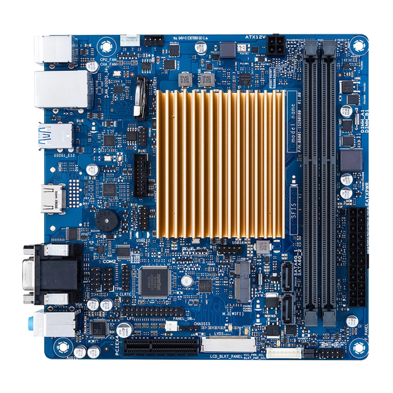
ATX12V LAN_U32G1_34 8111H U32G1_E12 128Mb BIOS Intel ® 1042A J3455 Place this side towards the rear HDMI of the chassis 1442K BUZZER USBE12 USB56 2166 COM2 Super 2230 AAFP CLRTC AUDIO CHASSIS PANEL_SW VCC_PWR_SEL PCIEX4 LVDS LCD_BLKT_PANEL F_PANEL BLKT_PWR_SEL J3455I-CM-A... - Page 10 Page Connectors/Jumpers/Slots CPU and chassis fan headers (4-pin CPU_FAN, 4-pin CHA_FAN) 2-12 USB 3.2 Gen 1 header (20-1 pin U32G1_12) 2-12 USB 2.0 headers (10-1pin USB_E12, USB56) 2-13 Built-in Intel Celeron Quad-core Processor J3455 ® ® ATX power connectors (24-pin EATXPWR, 4-pin ATX12V) 2-14 M.2 Wi-Fi 2-14...
-
Page 11: Central Processing Unit (Cpu)
(D/C) from the same vendor. Check with the vendor to get the correct memory modules. • According to Intel CPU spec, DIMM voltage below 1.35V is recommended to protect ® the CPU. Visit the ASUS website at www.asus.com for the latest QVL. J3455I-CM-A... - Page 12 Recommended memory configuration Installing a DIMM Chapter 2: Motherboard information...
- Page 13 To remove a DIMM J3455I-CM-A...
-
Page 14: Jumpers
Jumpers Clear RTC RAM (2-pin CLRTC) This header allows you to clear the CMOS RTC RAM data of the system setup information such as date, time, and system passwords. CLRTC Connector type HEADER 1x2p, 2.54mm pitch, S/T To erase the RTC RAM: Turn OFF the computer and unplug the power cord. - Page 15 The signal is then generated as a chassis intrusion event. CHASSIS PIN 1 Connector type HEADER 4p, K2, 2.54mm pitch Display panel VCC power selection (3-pin VCC_PWR_SEL) VCC_PWR_SEL LCD_VCC +5V +3V LCD_VCC (Default) Setting Pins 3.3V (Default) Connector type HEADER 1 x 3p, 2.54mm pitch, S/T J3455I-CM-A...
- Page 16 Display panel backlight power selection (3-pin BLKT_PWR_SEL) BLKT_PWR_SEL (Default) Pins 12V (Default) Connector type HEADER 1x3p, 2.54mm pitch, S/T Chapter 2: Motherboard information...
-
Page 17: Connectors
USB 3.2 Gen 1 devices can only be used for data storage. • We strongly recommend that you connect USB 3.2 Gen 1 devices to USB 3.2 Gen 1 ports for faster and better performance from your USB 3.2 Gen 1 devices. J3455I-CM-A 2-10... - Page 18 HDMI port. This port is for a High-Definition Multimedia Interface (HDMI) connector, and is HDCP compliant allowing playback of HD DVD, Blu-Ray, and other protected content. Serial port connector (COM). This port connects a modem, or other devices that conform with serial specification. 10.
-
Page 19: Internal Connectors
USB-chargeable devices, optimized power efficiency, and backward compatibility with USB 2.0. U32G1_12 PIN 1 +5V_USB3_P12 +5V_USB3_P12 S_U3RXDN1 S_U3RXDN2 S_U3RXDP1 S_U3RXDP2 S_U3TXDN1 S_U3TXDN2 S_U3TXDP1 S_U3TXDP2 S_U2DN1 S_U2DN2 S_U2DP1 S_U2DP2 Connector type BOX HD 2x10p, K20, 2.0mm pitch J3455I-CM-A 2-12... - Page 20 USB 2.0 header (10-pin USBE12, USB56) These headers are for USB 2.0 ports. Connect the USB cables to these headers. These USB headers comply with USB 2.0 specification that supports up to 480 Mbps connection speed. USBE12 PIN 1 USB+5V USB+5V USB_P1- USB_P2-...
- Page 21 ATX12V EATXPWR +3.3V +12V +12V +5VSB PIN 1 ATX_PSON#_R +3.3V -12V +3.3V +3.3V PIN 1 M.2 Wi-Fi This socket connects to an M.2 Wi-Fi device. M.2(WIFI) NOTE: The M.2 Wi-Fi module is purchased separately. J3455I-CM-A 2-14...
- Page 22 Front panel system panel header (10-1 pin F_PANEL) This header supports several chassis-mounted functions. +PWR_LED PWR_BTN PIN 1 +HDD_LED RESET Connector type Header 2x5p, K10, 2.54mm pitch • System power LED (2-pin +PWR_LED) This 2-pin header is for the system power LED. Connect the chassis power LED cable to this header.
- Page 23 Serial ATA 6.0Gb/s connectors (7-pin SATA6G_1/2) These connectors connect to Serial ATA 6.0 Gb/s hard disk drives or an optical drive via Serial ATA 6.0 Gb/s signal cables. RSATA_TXP RSATA_TXN SATA6G_1 RSATA_RXN SATA6G_2 RSATA_RXP Connector type WAFER HD 7p, 1.27mm pitch J3455I-CM-A 2-16...
- Page 24 LVDS connector (40-pin LVDS) This connector is for an LCD monitor that supports Low Voltage Differential Signalling (LVDS) interface. LVDS PIN 1 Connector type WAFER HD 2x15p, 1.25mm pitch 10. Panel switch (2-pin PANEL_SW) This 2-pin header is for connecting a monitor switch that can turn off the LCD panel display backlight.
- Page 25 • If you want to connect a high-definition front panel audio module to this header, set the HD Audio Controller item in the BIOS setup to [Enabled]. J3455I-CM-A 2-18...
- Page 26 13. Serial port header (10-pin COM2) This header is for a serial (COM) port. Connect the serial port cable to this header, then install the module to a slot opening at the back of the system chassis. COM2 RI1# CTS1# RTS1# DSR1# DTR1#...
- Page 27 J3455I-CM-A 2-20...
-
Page 28: Chapter 3 Bios Setup
Always shut down the system properly from the operating system. • Visit the ASUS website at www.asus.com to download the latest BIOS file for this motherboard. • The default BIOS settings for this motherboard apply to most working conditions and ensures optimal performance. - Page 29 For configuring options for special functions Tool For selecting the exit options and loading default settings Exit To select an item on the menu bar, press the right or left arrow key on the keyboard until the desired item is highlighted. J3455I-CM-A...
-
Page 30: My Favorites
My Favorites MyFavorites is your personal space where you can easily save and access your favorite BIOS items. Adding items to My Favorites To add frequently-used BIOS items to My Favorites: Use the arrow keys to select an item that you want to add. When using a mouse, hover the pointer to the item. -
Page 31: Main Menu
If you have set an administrator password, we recommend that you enter the administrator password for accessing the system. Otherwise, you might be able to see or change only selected fields in the BIOS setup program. To set an administrator password: J3455I-CM-A... - Page 32 • If you have forgotten your BIOS password, erase the CMOS Real Time Clock (RTC) RAM to clear the BIOS password. • The Administrator or User Password items on top of the screen show the default Not Installed. After you set a password, these items show Installed. Select the Administrator Password item and press <Enter>.
-
Page 33: Advanced Menu
(21.5\x22)] [Pixxo HP-A206D (21.5\x22)] [22AM33NB (21.5\x22)] [AUO (19.5\x22)] Improper selection of AiO chassis may result in incorrect operation or potential damage to AiO chassis hardware. EDID Data Source [Flat Panel Display] Allows you to select the EDID data source. Configuration options: [Pre-defined] [Flat Panel Display] J3455I-CM-A... - Page 34 Inverter Polarity [Normal] Allows you to select the inverter board polarity. Configuration options: [Inverted] [Normal] Screen Brightness [Neutral] Allows you to select screen brightness. Configuration options: [Dimmest] [Dimmer] [Dim] [Neutral] [Bright] [Brighter] [Brightest] Channel Select [Normal] Allows you to select the channel. Configuration options: [Dual Channel] [Single Channel] Mode Select [Normal] Allows you to select the mode.
-
Page 35: Onboard Devices Configuration
PXE OptionRom of the Realtek LAN controller. Configuration options: [On] [Off] Serial Port Configuration The sub-items in this menu allow you to set the serial port configuration. Serial Port [On] Allows you to enable or disable the serial port (COM). Configuration options: [On] [Off] J3455I-CM-A... -
Page 36: Apm
Change Settings [IO=3F8h; IRQ=4] Allows you to select the Serial Port base address. Configuration options: [IO=3F8h; IRQ=4] [IO=2F8h; IRQ=3] [IO=3E8h; IRQ=4] [IO=2E8h; IRQ=3] Serial Port 1 Configuration The sub-items in this menu allow you to set the serial port configuration. Serial Port [On] Allows you to enable or disable the serial port (COM). -
Page 37: Cpu Configuration
Automatic configuration. [Enabled] Enables the CPU C states. [Disabled] Disables the CPU C states. The following item appears only when you set the CPU C states to [Enabled]. Enhanced C-state [Enabled] [Enabled] Enables enhanced C-state. [Disabled] Disables enhanced C-state. 3-10 J3455I-CM-A... -
Page 38: Network Stack Configuration
Max package C State Support [Auto] Allows you to control the maximum Package C State that the processor supports. Configuration options: [PC2] [PC1] [C0] Max Core C State Support [Core C6] Allows you to control the maximum Core C State that the processors support. Configuration options: [Fused value] [Core C10] [Core C9] [Core C8] [Core C7] [Core C6] [Core C1] [Unlimited] 3.4.5... -
Page 39: Platform Trust Technology
While entering Setup, the BIOS automatically detects the presence of SATA devices. The SATA Port items show Not Present if no SATA device is installed to the corresponding SATA port. SATA Controller [Enable] Allows you to enable or disable the chipset SATA controller. Configuration options: [Enable] [Disable] 3-12 J3455I-CM-A... - Page 40 Aggressive LPM Support [Disabled] This item appears only when you set the previous item to [Enable] and is designed for LPM (link power management) support with a better energy saving condition. Configuration options: [Disabled] [Enabled] S.M.A.R.T. Status Check [On] S.M.A.R.T. (Self-Monitoring, Analysis and Reporting Technology) is a monitor system. When read/write of your hard disk errors occur, this feature allows the hard disk to report warning messages during the POST.
-
Page 41: Monitor Menu
CPU Fan Speed Low Limit [200 RPM] This item appears only when you enable the CPU Q-Fan Control feature and allows you to disable or set the CPU fan warning speed. Configuration options: [Ignore] [100RPM] [200RPM] [300 RPM] [400 RPM] [500 RPM] 3-14 J3455I-CM-A... -
Page 42: Chassis Q-Fan Control [Enabled]
CPU Fan Profile [Standard] This item appears only when you enable the CPU Q-Fan Control feature and allows you to set the appropriate performance level of the CPU fan. [Standard] Sets to [Standard] to make the CPU fan automatically adjust depending on the CPU temperature. - Page 43 Chassis Fan will operate at the minimum duty cycle. 3.5.6 Chassis Intrude Detect Support [Off] This item allows you to enable or disable the chassis intrusion detect function. Configuration options: [On] [Off] 3-16 J3455I-CM-A...
-
Page 44: Boot Menu
Boot menu The Boot menu items allow you to change the system boot options. 3.6.1 Fast Boot [Enabled] [Enabled] Select to accelerate the boot speed. [Disabled] Select to go back to normal boot. The following item appears when you set Fast Boot to [Enabled]. Next Boot after AC Power Loss [Normal Boot] [Normal Boot] Returns to normal boot on the next boot after AC power loss. -
Page 45: Bootup Numlock State [On]
[Both, Legacy OPROM first] [Both, UEFI first] [Legacy OPROM first] [UEFI driver first] [Ignore] Boot from PCI-E Expansion Devices [Legacy OPR...] Allows you to select the type of PCIe/PCI expansion devices that you want to launch. Configuration options: [Legacy OPROM first] [UEFI driver first] 3-18 J3455I-CM-A... -
Page 46: Secure Boot
3.6.6 Secure Boot Allows you to configure the Windows Secure Boot settings and manage its keys to protect ® the system from unauthorized access and malwares during POST. OS Type [Windows UEFI mode] Allows you to select your installed operating system. [Windows UEFI mode] Executes the Microsoft Secure Boot check. - Page 47 Append DBX from file Allows you to load the additional DBX from a storage device so that more db’s images cannot be loaded. The DBX file must be formatted as a UEFI variable structure with time-based authenticated variable. 3-20 J3455I-CM-A...
-
Page 48: Tool Menu
<Enter> to display the submenu. 3.7.1 ASUS EZ Flash 3 Utility Allows you to run ASUS EZ Flash 3. Press [Enter] to launch the ASUS EZ Flash 3 screen. 3.7.2 ASUS User Profile This item allows you to store or load multiple BIOS settings. -
Page 49: Exit Menu
<Esc>, a confirmation window appears. Select Yes to discard changes and exit. Launch EFI Shell from filesystem device This option allows you to attempt to launch the EFI Shell application (shellx64.efi) from one of the available devices that have a filesystem. 3-22 J3455I-CM-A... - Page 50 Appendix Notices FCC Compliance Information Responsible Party: Asus Computer International Address: 48720 Kato Rd., Fremont, CA 94538, USA Phone / Fax No: (510)739-3777 / (510)608-4555 This device complies with part 15 of the FCC Rules. Operation is subject to the following two conditions: (1) This device may not cause harmful interference, and (2) this device must accept any interference received, including interference that may cause undesired operation.
- Page 51 : (1) l’appareil ne doit pas produire de brouillage, et (2) l’utilisateur de l’appareil doit accepter tout brouillage radioélectrique subi, même si le brouillage est susceptible d’en compromettre le fonctionnement. CAN ICES-3(B)/NMB-3(B) VCCI: Japan Compliance Statement Class B ITE KC: Korea Warning Statement J3455I-CM-A...
- Page 52 ASUS products sold in Vietnam, on or after September 23, 2011,meet the requirements of the Vietnam Circular 30/2011/TT-BCT. Các sản phẩm ASUS bán tại Việt Nam, vào ngày 23 tháng 9 năm2011 trở về sau, đều phải đáp ứng các yêu cầu của Thông tư 30/2011/TT-BCT của Việt Nam.
- Page 53 ASUS Recycling/Takeback Services ASUS recycling and takeback programs come from our commitment to the highest standards for protecting our environment. We believe in providing solutions for you to be able to responsibly recycle our products, batteries, other components as well as the packaging materials.
-
Page 54: Asus Contact Information
+1-510-739-3777 +1-510-608-4555 Web site https://www.asus.com/us/ Technical Support Support fax +1-812-284-0883 Telephone +1-812-282-2787 Online support https://qr.asus.com/techserv ASUS COMPUTER GmbH (Germany and Austria) Address Harkortstrasse 21-23, 40880 Ratingen, Germany Web site https://www.asus.com/de Online contact https://www.asus.com/support/Product/ContactUs/ Services/questionform/?lang=de-de Technical Support Telephone (DE) +49-2102-5789557 Telephone (AT)
Need help?
Do you have a question about the J3455I-CM-A and is the answer not in the manual?
Questions and answers