Advertisement
Quick Links
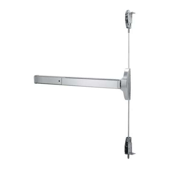
INSTALLATION INSTRUCTIONS
9600/F9600 SERIES
CONCEALED VERTICAL ROD EXIT DEVICE
1135-231
95057470
Note: One set of instructions should be left
with building owner after device has been
installed.
www.dorma-usa.com
1-800-523-8483
Index:
Screw chart
Tools required
Outside trim options
"03" Additional door prep
Device installation
Frame & strike preps
Final rod adjustment
Options available
Wood door preparation
5100 retro-fit preparation
Metal edge guard
Spotting template
1
2
3
4
5-10
11-12
13
14-16
17
18
19
20
I9600-1 4/2010
Advertisement

Related Manuals for Dorma 9600 Series


Summary of Contents for Dorma 9600 Series
- Page 1 11-12 Final rod adjustment Options available 14-16 Wood door preparation 5100 retro-fit preparation Metal edge guard Spotting template Note: One set of instructions should be left with building owner after device has been installed. 1135-231 95057470 I9600-1 4/2010 www.dorma-usa.com 1-800-523-8483...
- Page 2 SCREW CHART Chassis mounting (2) 12-24 x 1 1/2" F.H.P.M.S. (Metal or thru bolts) (2) #12 x 1 1/4" F.H.P.T.S. (Wood door) Chassis mounting (2) 12-24 x 1" R.H.P.M.S. (Metal or thru Bolts) End cap bracket (2) #12 x 1 1/4" R.H.P.T.S. (Wood door) End cap bracket Optional "WD"...
- Page 3 HANDING OF DOOR Read the entire instruction sheet prior to installation. Before Installing Hardware: 1. Verify door width, handing and product with carton label for correct exit device and length. (See Step 9) 2. For hand reversal of chassis see page 6, for outside lever trim see page (3). 3.
- Page 4 Key removed. legs of cam stradle actuator. Conventional 1 1/8" mortise cylinder #90X13SC118 supplied Locked with DORMA #13 cam, keyed position differently to a random combina- "09" Cam tion supplied with functions "08" & "11" trim unless otherwise...
- Page 5 ADDITIONAL DOOR PREP REQUIREMENTS 9600/F9600 Concealed Vertical Rod Exit Device RHR Shown LHR Opposite Required for "03" & "04" function on device with cylinder only and no trim. (NOT TO SCALE) NOTE: "04" function not NOTE: If using 80CK (SEE STEP 2) (SEE STEP 2) available on fire rate device.
- Page 6 With door lying on saw horses, open box, layout all parts and verify prior to starting installation. See page (1) one for parts. Note: If this is a retro-fit from current 5100 see page 18 prior to proceeding. Chassis Door preperation Chassis template vertical located at rear of...
- Page 7 If not done layout device on door using drilling template T9600 located at rear of booklet. For additional templates contact DORMA at 1-800-523-8483 or www.dorma-usa.com Refer to carton label for model and trim number prior to drilling. Prepare mounting holes and cut-outs per template.
- Page 8 Assemble rods, latches and adjust to preliminary length. Optional: "ALD" bracket Standard (NS) Top latch Narrow stile Thread on & rod aluminum door 5/8" Optional:"WD" "L" shaped mounting assembly. mounting bracket brackets for steel and wood door (installed at applications and all fire doors. factory).
- Page 9 Install rods in door and chassis as shown. Pivot connecting links down as shown and slide Fire Rated Devices Require latch assemblies into door. (2) "WD" "L" Shaped Brackets. As linkages reach cut outs in door guide them through as shown; Adjusting Screws "Loosen only";...
- Page 10 Install adjusting screws and connecting links to chassis. Top latch bolt should be fully extended and dead locked. Bell crank should be in full down position (home position). Connecting links should be about in center of cut out in bell crank. Install top and bottom adjusting screws (b) through both bell crank and Point in connecting link arms;...
- Page 11 Hang door in opening and ensure that it is square and plumb. Install touch bar and rail assembly and end cap to door. Remove two 8-32 screws from chassis, slide touch bar and rail assembly under rear of chassis. Note: If device has pre- fix "ES"...
- Page 12 FRAME PREPARATION #10-32 Tap (2) places 1 1/2" Reinforcement For 10-32 x 3/8" F.H.P.U.C.M.S. 3/4" 2" 15/16" 13/16" 1 1/2" 13/16" 13/16" 3/4" 1 5/8" 1 5/8" 19/32" 1 3/16" Of strike 1 5/8" 2" Mounted #418 strike Cut out dimensions Of strike No.
- Page 13 BOTTOM STRIKE PREPARATION Of strike 1" Inside face of door 1/4" Ref. 3/16" Ref. Finished floor Top of threshold Drill 13/16" Dia. 1" in depth. Of latch #439 Strike Optional pullman latch No. 431 strike installation Of strike 1/4"-20 x 1" 3/16"...
- Page 14 Adjustment of rods. G. Standing on inside, close door and check that top Block open door and bottom latch bolts align and engage in top and and release top bottom strikes. latch bolt as shown. H. After rods are fully adjusted ensure that top and Top latch should be bottom locking screws are tight.
- Page 15 NOTE: Touch bar must length. Additional hole re- be in dogged down po- quired see step 11. sition, to remove the Note: DORMA mortise rear filler panel. cylinder supplied. To use other manufacture cylinders, "L" less cylinder is available. 11/16" Min 1"...
- Page 16 Electrically retracts latchbolt(s) 12-24 Volt AC/DC Power Supply. when energized by power supply. i.e. DORMA ES100 etc., REQUIRES DORMA PS501 POWER SUPPLY Contact DORMA for other power AND ES105 POWER TRANSFER. supplies available. PS501 Will operate (2) "ES" 9600 exit devices, but is capable of powering (2) additional devices by installing the optional "ES-2"...
- Page 17 Note: Refer to DE9000 Series Installation Instructions for addtional instructions for installation and operation of the "Delayed Egress" exit device. 85 Decibel Alarm - Standard LED Status Indicator - Standard REQUIRES DORMA Nuisance Alarm - Standard ES-100 24 VDC POWER SUPPLY. Key Switch Control - Standard...
- Page 18 WOOD DOOR PREP SEE TEMPLATES FOR ACTUAL PRODUCT ONLINE AT www.dorma-usa.com 1 3/4" Min. 2 3/8" Std. 2 3/4" Min. 1 7/16" Min. Top & Bottom 3 3/8" Std. 1 1/2" 7/8" to Center Line of Routing 3/8" 1/4" 5/8"...
- Page 19 Use existing latch and chassis location. Note: new "Z" trim will be required if trim is used. Replace existing rod assemblies with new design. Follow instruction for installing new 9600 series device. Install chassis assembly to door, install end cap bracket to door, hold touch bar and rail...
- Page 20 METAL EDGE GUARD FOR FIRE RATED DOORS NOTE: Fire door application may require metal edge guard. See proper device and trim templates for addtional metal edge guard and hole preparation. RHR shown LHR opposite NO.21 drill 1 7/16" x 10-32 tap Double 1 1/8"...
- Page 21 VERTICAL REF. LINE VERTICAL REF. LINE (CENTERLINE OF CHASSIS) (CENTERLINE OF CHASSIS) EXIT DEVICE 3/4" X 1 5/8" 3/4" X 1 5/8" CUTOUT 9600/F9600 SERIES CUTOUT FOR ROD FOR ROD CONNECTION CONNECTION SEE PROPER SEE PROPER OUTSIDE DOOR OUTSIDE DOOR TRIM TEMPLATE OUTSIDE OUTSIDE...
- Page 22 For 7'5" door use 7'4" pre-drilled inner rod with 6'10" 1" pre-drilled outer rod; (6th hole on inner rod & 2nd hole on outer rod.) 6'8" 6'4" Inner rod Rod end is assembled to pivot connecting link Addendum page I9600 I9600RC-1 5/2010 www.dorma-usa.com 1-800-523-8483...
Need help?
Do you have a question about the 9600 Series and is the answer not in the manual?
Questions and answers