Table of Contents
Advertisement
Quick Links
INSTALLATION INSTRUCTIONS
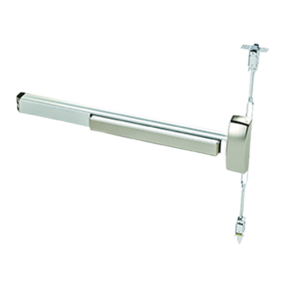
9800/F9800 SERIES
SURFACE VERTICAL ROD EXIT DEVICE
1135-233 95057472
www.dorma-usa.com
1-800-523-8483
Index:
Note: One set of instructions should be left
with building owner after device has been
installed.
1
2
3
4
5-12
13
14
14
14
15
16-17
18-21
22
I9800-1 4/2010
Advertisement
Table of Contents

Related Manuals for Dorma 9800 Series


Summary of Contents for Dorma 9800 Series
-
Page 1: Table Of Contents
Rod cutting Rod extension Popper details 5400 retro-fit preparation Options 16-17 18-21 Latch case templates Chassis spotting template Note: One set of instructions should be left with building owner after device has been installed. 1135-233 95057472 I9800-1 4/2010 www.dorma-usa.com 1-800-523-8483... -
Page 2: Screw Chart
SCREW CHART Chassis Mounting (2) 12-24 x 1 1/2" F.H.P.M.S. (Metal or Thru Bolts) (2) #12 x 1 1/4" F.H.P.T.S. (Wood Door) Chassis Mounting (2) 12-24 x 1" R.H.P.M.S. (Metal or Thru Bolts) End Cap Bracket (2) #12 x 1 1/4" R.H.P.T.S. (Wood Door) End Cap Bracket (1) 12-24 x 3/4"... -
Page 3: Tools Required
HANDING OF DOOR Read the entire instruction sheet prior to installation. Before Installing Hardware: 1. Verify door width, handing and product with carton label for correct exit device and length. (See Step 6) 2. For hand reversal of chassis see page 6, for outside lever trim see page (3). 3. -
Page 4: Outside Trim Options
Key removed. legs of cam stradle actuator. Conventional 1 1/8" mortise cylinder #90X13SC118 supplied Locked with DORMA #13 cam, keyed position differently to a random combina- "09" Cam tion supplied with functions "08" & "11" trim unless otherwise... -
Page 5: 03" Additional Door Prep
ADDITIONAL DOOR PREP REQUIREMENTS 9800/F9800 Surface Vertical Rod Exit Device RHR Shown LHR Opposite Required for "03" & "04" function on device with cylinder only and no trim. (NOT TO SCALE) NOTE: "04" function not NOTE: If using 80CK (SEE STEP 2) (SEE STEP 2) available on fire rate device. -
Page 6: Device Installation
With door lying on saw horses, open box, layout all parts and verify prior to starting installation. See page (1) one for parts. Note: If this is a retro-fit from current 5400 see page 15 prior to proceeding. Chassis Door preperation Chassis template vertical located at rear of... - Page 7 If not done layout device on door using drilling template T9800 located at rear of booklet. For additional templates contact DORMA at 1-800-523-8483 or www.dorma-usa.com Refer to carton label for model and trim number prior to drilling. Prepare mounting holes and cut-outs per template.
- Page 8 Prepare to install touch bar and rail on door. NOTE: All dimensions are based on 1/2" stop height; Verify strikes, stile width, any trim and stop height prior to making any cuts. If cutting is required follow instructions below. Size AA: Fits 48"...
- Page 9 Install touch bar and rail assembly and end cap to door. Remove two 8-32 screws from chassis, slide touch bar and rail assembly under rear of chassis. Note: If device has pre- fix "ES" ensure that pins in lever bolt align with slots in actuator located in- Hold rear mounting bracket tightly side nose of touch bar.
- Page 10 Install top and bottom latch case assemblies. No. 12 x 1" R.H.P.T.S. (Wood) 12-24 x 1/2" R.H.P.M.S. (Metal) Inter-locking strike angle 12-24 x 1 1/4" R.H.P. M.S. (Thru bolts) for fire rated doors over 8' and all fire rated LBR (less bottom rod) devices.
- Page 11 Check for proper function of device and top latch assembly. Depress touch bar slowly, top latch bolt should retract fully. Hold bar depressed, push in and hold top tripping lever. Latch bolt should be flush or slightly depress in top latch case. If this is found, release touch bar and tripping lever top latch bolt should remain captured by tripping lever.
- Page 12 Installation of bottom slide bolt or latch assembly. NOTE: If horizontal reference line is moved from the recommended mounting height, new rods may have to be ordered. Remove 8/32 x 1/2" phillips head If cutting is required "Do Not Cut screw from retaining Threaded End".
- Page 13 Verification of rod adjustments. G. Close door and check that top and bottom latch Block open door, bolts align and engage in top and bottom strikes. push inward on tripping lever and release top H. After rods are fully adjusted ensure that top and latch bolt as shown.
-
Page 14: Optional Bottom Strikes
OPTIONAL: BOTTOM STRIKE PREPARATION #416 Strike For surface strike drill (2) 5/16" diameter x 1" deep holes for anchors. 1 13/16" Edge of 5/8" door 3/16" 1/4" 2 3/8" 1/2" Ref. Ref. 5/8" 5/8" Top of Finished threshold floor Lead anchors #12 x 1"... -
Page 15: Rod Cutting
ROD CUTTING NOTE: Rods shipped standard from factory for 7' seven foot door opening. Optional rod pack for 8' eight foot openings available "must be noted at time of order". For doors under 7' seven foot subtract difference from bottom of top rod, cut per details and redrill hole for retaining plate. -
Page 16: 5400 Retro-Fit Preparation
RETROFIT FROM EXISTING 5400 TO NEW 9800 MODEL Existing vertical ref. line (Center line of chassis) 1 1/2" When using trim max. with outside cylinder. Outside face only. 1 3/4" 1" Dia. max. thru door for spindle 11/16" Existing horizontal ref. line Existing Holes Outside face... -
Page 17: Options
NOTE: Touch bar must length. Additional hole re- be in dogged down po- quired see step 6. sition, to remove the Note: DORMA mortise rear filler panel. cylinder supplied. To use other manufacture cylinders, "L" less cylinder is available. 11/16" Min 5/16"... - Page 18 Electrically retracts latchbolt(s) 12-24 Volt AC/DC Power Supply. when energized by power supply. i.e. DORMA ES100. REQUIRES DORMA PS501 POWER SUPPLY Contact DORMA for other power & ES105 POWER TRANFER. supplies available. PS501 Will operate (2) "ES" 9800 exit devices,...
-
Page 23: Chassis Spotting Template
RHRB LHRB VERTICAL REF. LINE VERTICAL REF. LINE (CENTERLINE OF CHASSIS) (CENTERLINE OF CHASSIS) EXIT DEVICE 9800/F9800 SERIES OUTSIDE OUTSIDE FACE ONLY FACE ONLY NOTE: FOR CYLINDER ONLY FUNCTION SEE PAGE 4 HORIZONTAL REFERENCE LINE Drawing not to Scale Use for Reference Only A FOR WOOD DOOR No.
Need help?
Do you have a question about the 9800 Series and is the answer not in the manual?
Questions and answers