Table of Contents
Advertisement
Quick Links
Advertisement
Table of Contents

Related Manuals for Spectra Precision ashtech ProFlex 800 CORS


Summary of Contents for Spectra Precision ashtech ProFlex 800 CORS
- Page 1 ProFlex 800 CORS ™ Getting Started Guide CORS Reference Station...
- Page 2 Copyright Notice FOR ANY PARTICULAR PURPOSE, MERCHANT- ABILITY OR NON-INFRINGEMENT, ARE HEREBY Copyright 2012 Ashtech. All rights reserved. DISCLAIMED AND IF APPLICABLE, IMPLIED WAR- Trademarks RANTIES UNDER ARTICLE 35 OF THE UNITED NA- TIONS CONVENTION ON CONTRACTS FOR THE All product and brand names mentioned in this pub- INTERNATIONAL SALE OF GOODS.
- Page 3 limitation of incidental or consequential damages shipping method such as UPS or FedEx when return- may not apply. ing a product for service. For further information concerning this limited war- 4. LIMITATION OF IMPLIED WARRANTIES ranty, please call or write: EXCEPT AS SET FORTH IN ITEM 1 ABOVE, ALL Ashtech SAS - ZAC La Fleuriaye - BP 433 - 44474 OTHER EXPRESSED OR IMPLIED WARRANTIES,...
- Page 4 EVENT WILL ASHTECH BE RESPONSIBLE FOR SUCH DAMAGES, EVEN IF ASHTECH HAS BEEN ADVISED OF THE POSSIBILITY OF SUCH DAMAG- Some national, state, or local laws do not allow the exclusion or limitation of incidental or consequential damages, so the above limitation or exclusion may not apply to you.
-
Page 5: Table Of Contents
Table of Contents What is ProFlex 800 CORS? ..............1 Hardware Description................3 System Components Overview ..........3 Basic Supply ..............3 Optional Accessories ............4 Equipment Description & Basic Functions........5 Front View .................5 Rear View ................7 Buzzer ................9 Battery Model & Battery Compartment .........9 Special Button Combinations ..........10 Charging Batteries Before Use ..........10 Removing the Battery from the ProFlex 800......11... - Page 6 Angle Units ..............39 Time Units ..............40 Setting a CORS Reference Station............41 How to Start................41 General Parameters..............41 Defining the Raw Data Generated by the CORS Station ...43 Programming Sessions ............44 Starting Sessions & Managing Raw Data Files......45 Programming Email Notifications .........47 Activating the Embedded FTP Server &...
-
Page 7: What Is Proflex 800 Cors
What is ProFlex 800 CORS? ProFlex 800 CORS is a rugged and high-performance CORS reference station. Designed as an extension of the ProFlex 800 receiver, ProFlex 800 CORS integrates the best of today’s technologies, including the exclusive Z-Blade™ algorithms and multi-constellation (GPS+GLONASS+ GALILEO+SBAS) capabilities. - Page 8 makes it possible to access various sources of data from different base stations through a single Internet connection, as well as efficiently protect these sources of corrections from unauthorized users. The embedded NTRIP caster allows you to organize a network of up to 10 different mount points (each of them receiving corrections from an NTRIP server) and up to 100 users given the ability to receiver corrections through these mount points.
-
Page 9: Hardware Description
Hardware Description System The tables below provide an overview of the different key items composing the ProFlex 800 CORS. Components Depending on your purchase, you may only have some of the Overview listed items. Please refer to the packing list for an accurate description of the equipment that has been delivered to you. -
Page 10: Optional Accessories
Item Part Number Picture AC/DC Power Supply Kit (includes external AC adapter, battery charger and cable extension for 802064 powering ProFlex 800 directly from the AC adapter) ProFlex 800 User Documentation CD 501510 Optional Accessories Item Part Number Picture L1/L2 GNSS Antenna 111406 Choke ring installation kit for GNSS antenna 802093... -
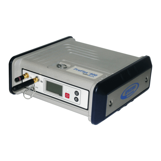
Page 11: Equipment Description & Basic Functions
Equipment Description & Basic Functions Front View From left to right: Bluetooth Antenna. A coaxial female connector (reverse SMA type) allowing you to connect a Bluetooth antenna for wireless communication with a field terminal or other device. Cellular Antenna. A coaxial female connector (SMA type) allowing you to connect a cellular antenna. - Page 12 USB Host & Device. A nine-contact female connector (Fischer type). Depending on how it is configured, the USB port can be used in two different ways: 1. For a USB host, such as a mass storage device using optional device cable P/N 702104. 2.
-
Page 13: Rear View
Log Button. Press this button briefly to start recording raw data on the selected storage medium. Another short press on this button will immediately stop raw data recording. Scroll button. Press this button briefly to scroll through the different pages of information viewed on the screen. If an alarm is reported on the display screen, a short press on the Scroll button will acknowledge the alarm. - Page 14 Serial Data Ports. These are all Fischer, seven-contact, female connectors, each allowing a serial connection to an external device. • Ports F [3] and B [4] are both RS232-only ports • RS232/422 Port A [5] is a switchable RS232/RS422 port (Default is RS232).
-
Page 15: Buzzer
CAN 2.0 Bus. A Fischer, five-contact, female connector [9] allowing you to connect the ProFlex 800 to external, NMEA2000-compatible equipment via CAN bus. (For future use.) Earth Terminal. A screw terminal [10] for connecting the receiver chassis to Earth. Electric Isolation. All signals available on the following connectors are optically isolated from the receiver’s internal circuitry and chassis ground, as well as from each other: •... -
Page 16: Special Button Combinations
The battery is housed in a battery compartment accessible from above the ProFlex 800. The compartment door can be opened by lifting and then turning the quarter-turn finger screw counter-clockwise. The battery will automatically operate as a backup power source for the receiver if for some reason the external DC source used is removed from the DC power input. -
Page 17: Removing The Battery From The Proflex 800
for several hours after a power shutdown, giving you the time to take the necessary maintenance steps. Follow the instructions below to charge a battery. Removing the Battery from the ProFlex 800 Unless the battery has already been taken out, do the following: •... -
Page 18: Inserting The Battery In The Proflex 800
• Plug the adapter into an AC outlet. Battery charging starts immediately. For a low battery that’s being charged, you will first see the three LEDs switch on and off, one after the other, followed by a short period of time when none of the LEDs is on (see [3]). -
Page 19: Power-On Screen
Power-On Screen When you power on the receiver, the Ashtech logo appears on the screen. It is displayed until the receiver has completed its auto-test (this takes about 30 seconds). Then the General Status screen is displayed. General Status Screen An example of General Status screen is shown below. - Page 20 • Raw data logging icon [5]: Data recording through front panel Log button or using Recording submenu in the Web Server: – Blinking: Raw data logging in progress – Fixed: No raw data logging in progress. Data recording through sessions: –...
-
Page 21: Memory Screens
Icon Definition Blinking icon: Modem turned on but not initialized yet. Indicates signal strength at modem antenna input. Fixed icon: Modem turned on and initialized (ready for a connec- tion). Indicates signal strength received at modem antenna input. The higher the number of bars, the better the signal. This icon will show four horizontal bars at the bottom when the input signal is zero. -
Page 22: Receiver Identification Screen
• Third line: Percentage of free space on the USB mass storage device. • Fourth line: Number of files currently stored on the USB mass storage device. Right screen: • First line: Total space occupied by the files currently stored in the internal memory. •... -
Page 23: Atl Recording Screen
of the reference position assigned to the base (not a computed position). See example below. The upper line contains the same information as in the upper line of the General Status screen. A new press on the Scroll button will take you to the ATL Recording screen (see below). -
Page 24: Screen Backlight
• When enough ATL data have been recorded (Tech Support will usually indicate the duration of ATL data collection needed for troubleshooting), then come back to the ATL Recording screen and simply press on the Log button again to stop the recording. NOTE 1: ATL data recording is totally independent of raw data recording: controlling ATL recording is done exclusively from the ATL recording screen, and raw data recording from... - Page 25 Power Line Power Line Jack AC/DC Power Charger Supply Kit “Y” Cable P/N 702501 P/N 802064 Fuse Battery Cable P/N 702473 ProFlex 800 CORS External 9- to 36-V DC Power Source Note that the battery used will not be charged from the AC/ DC supply kit.
-
Page 26: Introduction To Proflex 800 Cors Configuration
Introduction to ProFlex 800 CORS Configuration Introductory Notes This section more particularly focuses on how to successfully configure the ProFlex 800 CORS using the ProFlex Web Server. A few status screens are also presented. It is assumed that you have all the information needed perform an IP connection from your computer to the ProFlex 800 CORS. -
Page 27: Creating Sessions
2. Opening the Configuration tab to enter the general settings common to any base or reference station. 3. Still on the Configuration tab, entering the settings specific to the ProFlex 800 CORS. Before doing that, we encourage you to read the following topics: –... - Page 28 8:00 9:00 10:00 11:00 12:00 Session No. 1 (A) Session No. 2 (B) Session No. 3 (C) Session No. 4 (D) Raw data files (G-files) covering one hour each Sessions can be created either automatically (in this case they are all of the same duration), or created individually through a manual procedure.
-
Page 29: Raw Data Types And Files Collected During Sessions
For example, with Reference Day=33 (Feb 2), if the current day is 30 (Jan 30), the station will start the first session only in three days, whereas if the current day is 51 (Feb 20), the station will start the programmed sessions on that day. -
Page 30: Converting/Deleting G-Files Collected During Sessions
receiver to automatically delete the oldest G-file when the amount of available free memory (in the selected storage device) falls below 15 Mbytes. Converting/ G-files can be converted to Rinex 2.11 or 3.01, with or without the Hatanaka option. This will happen only if ATOM Deleting G-Files navigation data are included in the G-file (the conversion will Collected During... -
Page 31: Pushing Files Originating From Sessions To An External Ftp Server - Backup Ftp Server
Root Sitename Year Day 1 G-files and/or e.g. 1001 e.g. 2010 e.g. 121 converted files Day 2 G-files and/or converted files Organizing the storage of the files is simply obtained by typing the appropriate codification of the subdirectories in the field named Sub-directory Name Format. This field uses a specific syntax with case-sensitive characters. - Page 32 External FTP Server IP address or server name ProFlex 800 (Client) Internet Ethernet End users Raw Data Files The reference station being the client for this transfer, you need to enter the IP address (or host name) and IP port of the remote FTP server, and also enter the login and password that will let the receiver upload its files to the server without any problem.
-
Page 33: Recording Raw Data Outside Of Any Sessions
• Permanently, as a second repository for all the files collected by the CORS station. Recording Raw Raw data recording can also take place outside of any sessions. What’s more, it can take place simultaneously with Data Outside of data recording performed through the programmed sessions. Any Sessions This alternate recording capability can be controlled through the Configuration - Recording submenu in the ProFlex Web... -
Page 34: Embedded Ntrip Caster
Embedded NTRIP Introduction Caster The Embedded NTRIP Caster allows you to build your own NTRIP network solution around the ProFlex 800 CORS station. The embedded NTRIP caster can handle a total of 100 users and 10 mount points. The number of 100 users should be understood at the total number of possible users, irrespective of the mount points they are using. - Page 35 Reference Position NTRIP servers 1 and 2 may be connected to the Base embedded NTRIP caster (local host) or to an external NTRIP caster. Differential Differential Stream 1 Stream 2 NTRIP NTRIP NTRIP Server 1 Server 2 Caster Port P Port Q (IP Server) (IP client)
-
Page 36: Ntrip Caster Control & Monitoring
Reference Position Base Differential Stream 1 or 2 NTRIP Server NTRIP 1 or 2 Caster Port P or Q (IP Server) (IP client) ProFlex 800 (Ethernet Port) Internet NTRIP Clients (Users) (IP clients) NTRIP Caster Control & Monitoring The ProFlex Web Server provides an easy way to remote control and monitor the Embedded NTRIP caster. - Page 37 • The Mount Points submenu allows you to define each of the possible 10 mount points of the NTRIP caster. Choosing the name of a mount point is important: – it is through that name that NTRIP servers can connect to the NTRIP caster.
-
Page 38: Map
The Web Server provides a map of the NTRIP caster network using different colors to show the location of the caster, of the NTRIP servers (bases) and of the different users. Protecting Mount Points Protecting mount points may be done in an indirect way, as explained below: •... -
Page 39: Embedded Ftp Server
Administrator SMTP Server Computer ProFlex 800 Alarm email Internet Ethernet Alarm email You may choose between three different levels of notification: • Full notification. Each of the following events will generate an email: – “High” and “medium” alarms – Receiver powered on –... -
Page 40: External Sensors
receiver memory and directory via an IP connection, using the FTP communication protocol. In this case, end users should be given read access (through a user profile) to the directory containing the raw data files collected by the receiver. Alternatively, as the owner of the station, you may have to perform remote maintenance operations in the receiver memory. - Page 41 also be saved as a D-files, in which case the D-files are saved in the same subdirectory as the corresponding G-files. Sensor data can also be output through the NMEA XDR message type. External sensors can be connected to the ProFlex 800 using multi-function serial cable P/N 702450 (3 meters in length).
-
Page 42: First Steps With The Web Server
First Steps With the Web Server Home Tab The Web Server Home tab appears after you have typed the correct IP address in the Address box of your web browser and pressed the Enter key. In the right-upper corner of the window, you have access to the on-line help (HELP link) and to technical support (SUPPORT link). -
Page 43: Status Bar And Units Used
these parameters. For your information, the third column indicates the relevant $PASH commands. Parameter Designation $PASH Receiver serial Hardware-coded receiver serial number $PASHQ,RID number Owner name Owner name $PASHS,WEB,OWN Company Name of the company operating the $PASHS,WEB,OWN name receiver Phone Contact phone number $PASHS,WEB,OWN Email... - Page 44 By column from left to right: Column #1 Receiver operating mode (“Base”, “Rover”, “Rover/Heading” or “Hot Standby Mode RTK”) Type of position solution currently available from the receiver (“No position”, Position “Autonomous”, “DGPS”, “S-DGPS”, “RTK Fixed” or “RTK Float”) If a base: •...
-
Page 45: Distance Units
Indicates whether the recorded raw data files are uploaded to an external FTP FTP Push server (“On”) or not (“Off”). Column #8 Date Current date (YYYY-MM-DD) Time Current local or UTC time (hh:mm:ss) according to the setting below. Blank area if no alarm has been detected. “Alarms”... -
Page 46: Time Units
Angle Unit Latitude Format Longitude Format Used Deg. Min. DD°MM’ SS.SSSSS” N or DDD°MM’ SS.SSSSS” E or Sec. DD°MM’ SS.SSSSS” S DDD°MM’ SS.SSSSS” W Where: • N for North, S for South; E for East, W for West • “D..” for degree digits, “M..” for minute digits, “S..” for second digits When typing in a latitude or longitude, leading and trailing zeroes can be omitted. -
Page 47: Setting A Cors Reference Station
Setting a CORS Reference Station • Open the Web Server’s Configuration tab. The first time you How to Start click on this tab, the Web Server will ask you to log in as the administrator. Only the receiver administrator is authorize d to access the Configuration tab. - Page 48 – Antenna Radius: In case of a “Slant Height” measurement, enter the antenna radius (this is a manufacturer specification), taking care to enter this parameter in the selected distance unit. See also the diagram below for more information. – SHMP Offset: In case of a “Slant Height” measurement, enter the SHMP offset (this is a manufacturer specification) taking care to enter this parameter in the selected distance unit.
-
Page 49: Defining The Raw Data Generated By The Cors Station
Click on Data Output and then on the Raw Data submenu. Use Defining the Raw the page that opens as explained below: Data Generated by • All ATOM and Ashtech legacy raw data message types are the CORS Station listed below. Format Message types ATOM... -
Page 50: Programming Sessions
Warning! The rates of message types RNX (ATOM message type) and MPC (Ashtech legacy message type) are in fact defined by the Recording Interval parameter on the Sessions - Scheduling web page (see Programming Sessions on page 44). The value you might enter on the Raw Data web page for these messages would anyway be ignored. -
Page 51: Starting Sessions & Managing Raw Data Files
Clicking in a row inside the table allows you to edit the session individually. The changes are then entered by clicking on the Manual Set button Note that the Use button is checked by default, which means data recording is allowed during the session. Starting Sessions To start the execution of the programmed sessions on the current day, do the following:... - Page 52 • Check the Ring File Memory option. This will result in an unlimited operating time for the station while using a finite memory size. • Data Type recalls the type of raw data collected through sessions. • You may want to save receiver power between sessions when those are separated by more than 15 minutes of idle time.
-
Page 53: Programming Email Notifications
• Using the different fields in the Transfer to external FTP Server pane, choose whether you want the receiver to automatically transfer the collected raw data files (original and/or converted files) to an external FTP server. If so, activate the Automatic Transfer option and enter the identification parameters of the FTP server: –... -
Page 54: Activating The Embedded Ftp Server & Creating New Users
– SMTP Server and SMTP Port: Enter respectively the name and port of the server in charge of routing the emails issued by the receiver. The SMTP server you need to use depends on the network the receiver is connected to. In most cases, it is the one of your Internet Service Provider. -
Page 55: Setting The External Sensors
– In the Memory Location field, choose the memory the FTP server will give access to. – In the FTP Path field, specify the path to the subdirectory (in the selected memory) the FTP server will have access to (syntax: /subdirectory/.../ subdirectory/). -
Page 56: Adding Delivery Of Real-Time Rtk Corrections
– Set the port’s Baud Rate and RTS/CTS – Enter the Initialization String and Trigger String. These are parameters specific to the sensor used. They should normally be found in the manufacturer’s documentation. – Set the interval of time, in seconds, through which the receiver queries the meteorological unit (Interval). -
Page 57: Ntrip Server Via Ethernet
For more information on the various possibilities of routing differential data to users, refer to the ProFlex 800 Web Server Getting Started Guide or the ProFlex 800 Reference Manual. • Click on Base Setup > NTRIP Server. NTRIP Server Via Ethernet •... - Page 58 By default the Caster Hostname or IP Address field shows the local IP address of the receiver (the one that can be read on the receiver display screen). If the Ethernet port is set to work in DHCP and you have declared a hostname on the DynDNS site, then the field should be updated to hold that hostname.
- Page 59 ATOM differential data in compact format could be named: “Balv_ATO_Sc100”. • After all the fields on the tab have been defined for a mount point, click on the Add/Modify button to save this mount point (there is no Configure button on the Mount Points tab).
-
Page 60: Monitoring Proflex 800 Cors
Monitoring ProFlex Reading the Status pages of the ProFlex Web Server is a nice way of monitoring ProFlex 800 CORS through an IP 800 CORS connection. Opening the web pages requires that you log in either as the administrator or as a simple user. This section gives a quick overview of the monitoring function. - Page 61 Index Symbols $PASH commands 36 Data output, CORS 43 Numerics Data recording (out of sessions) 27 Data Streaming on IP 50 702450 (cable) 35 Data transfer screen 18 Date 39 AC/DC power supply kit 4 DC power input 7 Address box 36 Delete Files After Transfer 26 Administrator profile 37 DHCP 52...
- Page 62 Height 38 Path 26 Home tab 36 Phone (owner phone) 37 Host cable (USB) 3 Port P 28 HRMS 38 Port Q 28 Position computation screen 16 Power button 6 Initialization String 50 Power LED 6 Power status 14 Key combinations 10 Power-on screen 13 Primary FTP server 25 L1 phase center 41...
- Page 63 SMTP server 48 Standard Notification 33 Station ID 38 Status (position) 13 Status bar 37 Status tab 37 Storage medium 24 Sub-directory Name Format 25 TarZ 24 Tiltmeter 34 Time 39 TNC/TNC coaxial cable 4 Trigger String 50 UHF input 8 Units used 39 USB device 23 USB port 6...
- Page 64 ©2012 Trimble Navigation Limited. All rights reserved. Spectra Precision is a Division of Trimble Navigation Limited. Spectra Precision and the Spectra Precision logo are trademarks of Trimble Navigation Limited or its subsidiaries. Ashtech and ProFlex are trademarks of Ashtech S.A.S. or its subsidiaries.
Need help?
Do you have a question about the ashtech ProFlex 800 CORS and is the answer not in the manual?
Questions and answers