Renishaw RENGAGE RMP600 Installation Manual
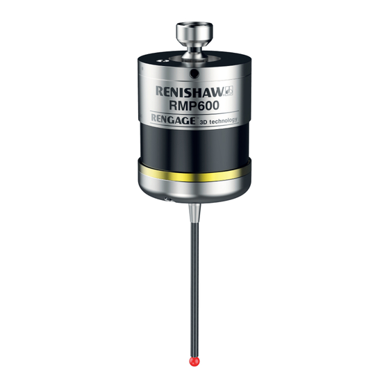
High-accuracy radio machine probe
Hide thumbs
Also See for RENGAGE RMP600:
- Quick start manual (212 pages) ,
- Installation manual (62 pages) ,
- Installation manual (48 pages)
Table of Contents
Advertisement
Quick Links
Advertisement
Table of Contents

Subscribe to Our Youtube Channel
Related Manuals for Renishaw RENGAGE RMP600


Summary of Contents for Renishaw RENGAGE RMP600
- Page 1 Installation guide H-5312-8503-08-B RMP600 high-accuracy radio machine probe...
- Page 2 This document may not be copied or reproduced in whole or in part, or transferred to any other media or language, by any means, without the prior written permission of Renishaw. Renishaw plc. Registered in England and Wales. Company no: 1106260. Registered office: New Mills, Wotton-under-Edge, Gloucestershire, GL12 8JR, UK.
-
Page 3: Table Of Contents
Contents Before you begin ............. 1.1 Disclaimer . - Page 4 RMP600 installation guide System installation ............3.1 Installing the RMP600 with an RMI or RMI-Q .
-
Page 5: Before You Begin
Renishaw office. Renishaw warrants its equipment and software for a limited period (as set out in the Standard Terms and Conditions), provided that they are installed and used exactly as defined in associated Renishaw documentation. -
Page 6: Cnc Machines
Care of the probe Keep system components clean and treat the probe as a precision tool. Patents Features of the RMP600, and other similar Renishaw products, are the subject of one or more of the following patents and/or patent applications: CN 100416216... -
Page 7: Microchip Software Licensing Agreement
Microchip software licensing agreement This product’s firmware has been developed by Renishaw with the use of the Microchip libraries, under the following licensing terms:- This software is developed by Microchip Technology Inc. and its subsidiaries (“Microchip”). Redistribution and use in source and binary forms, with or without modification, are permitted provided... -
Page 8: Intended Use
Ensure that you comply with international and national battery transport regulations when transporting batteries or this product with the batteries inserted. To reduce the risk of shipment delays, should you need to return this product to Renishaw for any reason, do not return any batteries. Information to the machine supplier/installer It is the machine supplier’s responsibility to ensure that the user is made aware of any hazards... - Page 9 Information to the equipment installer All Renishaw equipment is designed to comply with the relevant EU and FCC regulatory requirements. It is the responsibility of the equipment installer to ensure that the following guidelines are adhered to, in order for the product to function in accordance with these regulations: •...
- Page 10 RMP600 installation guide This page is intentionally left blank.
-
Page 11: Rmp600 Basics
see Section 2, “RMP60 basics” RMP600 basics Introduction The RMP600 probe offers an unrivalled combination of size, accuracy, reliability and robustness and, for the first time, allows high-accuracy probing on large machining centres or other machines where line-of-sight problems affect optical signal transmission. Successfully combining patented RENGAGE™... -
Page 12: Getting Started
RMP600 probe and the machine controller. For more details, refer to the RMI-Q radio machine interface installation guide (Renishaw part no. H-5687-8504). RMP600 is also compatible with the older radio machine interface (RMI) integrated interface/receiver. For more details, refer to the RMI radio machine interface installation guide (Renishaw part no. H-4113-8554). Trigger Logic™... -
Page 13: Probe Modes
Probe modes The RMP600 probe can be in one of three modes: Standby mode – Probe is waiting for a switch-on signal. NOTE: The RMP600 will enter “hibernation mode” should the system interface be powered off or out of range for a period of 30 seconds (“hibernation mode” is only applicable to “radio on mode”). Operational mode –... - Page 14 For more information on the user selectable switch-on time when operating with RMI-Q, refer to the RMI-Q installation guide (Renishaw part no. H-5687-8504). In “radio on mode”, the switch-on time assumes a good radio communication link. In a poor radio frequency (RF) environment this may rise to a maximum of 3 seconds.
-
Page 15: Enhanced Trigger Filter
“shank on / shank off” to be used with a single RMI or RMI-Q. Up to four RMP600s can be used with a single RMI-Q in “radio on / radio off mode”. For further details of this functionality, refer to the RMI-Q radio machine interface installation guide (Renishaw part no. H-5687-8504). -
Page 16: Acquisition Mode
NOTES: Systems using the RMI-Q can be partnered with up to four RMP600s manually. Alternatively, this can be achieved by using ReniKey; a Renishaw machine macro cycle which does not require the RMI-Q to be power cycled. For more information or to download ReniKey free of charge visit: www.renishaw.com/mtpsupport/renikey... -
Page 17: Rmp600 Dimensions
RMP600 dimensions 50 (1.97) 19 (0.75) Battery cassette Shank switch (optional) A range of probe-ready shanks is available from Renishaw M4 stylus 15° 15° XY overtravel Probe status LED 76 (2.99) Window Dimensions given in mm (in) Stylus overtravel limits Stylus length ±X/±Y... -
Page 18: Rmp600 Specification
RMP600 installation guide RMP600 specification Principal application Workpiece inspection and job set-up on multi-tasking machines, machining centres and gantry machining centres. Dimensions Length 76 mm (2.99 in) Diameter 63 mm (2.48 in) Weight (without shank) With batteries 1010 g (35.65 oz) Without batteries 940 g (33.18 oz) Transmission type... -
Page 19: Typical Battery Life
Environment IP rating IPX8, BS EN 60529:1992+A2:2013 IK rating IK01, BS EN 62262:2002+A1:2021 [for glass window] Storage temperature −10 °C to +70 °C (+14 °F to +158 °F) Operating temperature +5 °C to +50 °C (+41 °F to +122 °F) Battery types 2 ×... -
Page 20: Recommended Styli
RMP600 installation guide Recommended styli High modulus carbon fibre styli are designed to minimise pre-travel and improve accuracy, as the stem material is extremely stiff. This inherent stiffness makes the following styli most suitable for strain gauge applications. 2.10 Part number A-5003-7306 A-5003-6510 A-5003-6511... -
Page 21: System Installation
see Section 3, “System installation” System installation Installing the RMP600 with an RMI or RMI-Q CNC machining centre spindle RMI or RMI-Q Mounting interface bracket RMP600 inspection probe machine controller Cable Stylus RTS probe Workpiece Operating envelope Radio transmission does not require line-of-sight between the probe and transmitter, and will pass through very small gaps and machine tool windows. -
Page 22: Positioning The Rmp600 And Rmi Or Rmi-Q
RMP600 installation guide Positioning the RMP600 and RMI or RMI-Q The probe system should be positioned so that the optimum range can be achieved over the full travel of the machine’s axes. Always face the front cover of the RMI or RMI-Q in the general direction of the machining area and the tool magazine, ensuring both are within the performance envelope shown below. -
Page 23: Preparing The Rmp600 For Use
Preparing the RMP600 for use Fitting the stylus 1.8 Nm – 2.2 Nm (1.3 lbf.ft – 1.6 lbf.ft) M-5000-3707... -
Page 24: Installing The Batteries
RMP600 installation guide Installing the batteries NOTES: See Section 5, “Maintenance” for a list of suitable battery types. Ensure the product is clean and dry before inserting batteries. Do not allow coolant or debris to enter the battery compartment. After inserting the batteries the LEDs will display the current probe settings (for more information, see page 4.1 “Reviewing the probe settings”). -
Page 25: Mounting The Probe On A Shank
Mounting the probe on a shank NOTE: Where the RMP600 is to be used with a shank switch, remove the plug from the rear of the probe using pliers and replace it with the bobbin (A-4038-0303). 4 mm A/F × 2 ×... -
Page 26: Stylus On-Centre Adjustment
RMP600 installation guide Stylus on-centre adjustment NOTES: During adjustment, care must be taken not to rotate the probe relative to the shank, as damage to the bobbin (A-4038-0303) can occur where fitted. If a probe and shank assembly is dropped, it must be rechecked for correct on-centre adjustment. Do not hit or tap the probe to achieve on-centre adjustment. -
Page 27: Calibrating The Rmp600
Calibrating the RMP600 Why calibrate a probe? A spindle probe is just one component of the measurement system which communicates with the machine tool. Each part of the system can introduce a constant difference between the position that the stylus touches and the position that is reported to the machine. If the probe is not calibrated, this difference will appear as an inaccuracy in the measurement. -
Page 28: Calibrating In A Ring Gauge Or On A Datum Sphere
RMP600 installation guide Calibrating in a ring gauge or on a datum sphere Calibrating a probe either in a ring gauge or on a datum sphere with a known diameter automatically stores one or more value for the radius of the stylus ball. The stored values are then used automatically by the measuring cycles to give the true size of the feature. -
Page 29: Trigger Logic
see Section 4, “Trigger Logic™” Trigger Logic™ Reviewing the probe settings LED check > 5 s Key to the symbols LED short flash LED long flash Switch-on method Radio on Shank on Spin on (omitted if “multiple probe mode” was selected) or Switch-off method (omitted for shank on) Radio off or Short timeout... -
Page 30: Multiple Probe Mode Settings
RMP600 installation guide Multiple probe mode settings (RMI-Q application only) Deflect the stylus for less than 4 seconds to cycle to the next setting. Multiple probe mode Mode off Mode on Machine 4 Machine 1 Machine 2 Machine 3 Machine 5 Machine 6 Machine 7 Machine 8... -
Page 31: Probe Settings Record
Probe settings record This page is provided to note your probe’s settings. tick Factory settings settings Switch-on method Radio on Shank on Spin on Switch-off method Radio off or spin off or shank off Short timeout (12 s) Medium timeout (33 s) Long timeout (134 s) Enhanced trigger... -
Page 32: Changing The Probe Settings
RMP600 installation guide Changing the probe settings Insert the batteries or, if they have already been installed, remove them for five seconds and then refit them. Following the LED check, immediately deflect the stylus and hold it deflected until five red flashes have been observed (if the battery power is low, each red flash will be followed by a blue flash). - Page 33 Return to “Switch-on method” complete NOTES: If using “Multiple probe mode”, refer to the RMI radio machine interface installation guide (Renishaw part no. H-4113-8554) or the RMI-Q radio machine interface installation guide (Renishaw part no. H-5687-8504). Further probes used require the same “Multiple probe mode” setting, but do not need to be partnered with the RMI or RMI-Q.
-
Page 34: Rmp600 - Rmi Partnership
New partner radio probe acquired NOTE: Refer to the RMI radio The probe is now in standby machine interface installation and the system is ready for use. > 20 s guide (Renishaw part no. H-4113-8554) when partnering the RMP600. -
Page 35: Rmp600 - Rmi-Q Partnership
New radio probe acquired Displayed for 5 seconds NOTE: Refer to the RMI-Q radio machine interface installation guide (Renishaw part no. The probe is now in standby H-5687-8504) when partnering up and the system is ready for use. to four radio probes. -
Page 36: Operating Mode
RMP600 installation guide Operating mode LEDs LEDs LEDs flashing flashing flashing green Probe status LEDs LED colour Probe status Graphic hint Flashing green Probe seated in operating mode Flashing red Probe triggered in operating mode Flashing green and blue Probe seated in operating mode – low battery Flashing red and blue Probe triggered in operating mode –... -
Page 37: Maintenance
Maintenance You may undertake the maintenance routines described in these instructions. Further dismantling and repair of Renishaw equipment is a highly specialised operation, which must be carried out at an authorised Renishaw Service Centre. Equipment requiring repair, overhaul or attention under warranty should be returned to your supplier. -
Page 38: Changing The Batteries
RMP600 installation guide Changing the batteries CAUTIONS: Do not leave dead batteries in the probe. When changing batteries, do not allow coolant or debris to enter the battery compartment. When changing batteries, check that the battery polarity is correct. Take care to avoid damaging the battery cassette gasket. Only use specified batteries. - Page 39 NOTES: After removing the old batteries, wait more than 5 seconds before inserting the new batteries. Do not mix new and used batteries or battery types, as this will result in reduced life and damage to the batteries. Always ensure that the cassette gasket and mating surfaces are clean and free from dirt before reassembly.
-
Page 40: Diaphragm Replacement
RMP600 installation guide Diaphragm replacement RMP600 diaphragms The probe mechanism is protected from coolant and debris by two diaphragms. These provide adequate protection under normal working conditions. You should periodically check the outer diaphragm for signs of damage. If this is evident, replace the outer diaphragm. -
Page 41: Fault-Finding
see Section 6,“Fault-finding” Fault-finding Symptom Cause Action The probe fails to Dead batteries. Change batteries. power up (no LEDs Unsuitable batteries. Fit suitable batteries. illuminated or fails to indicate current Batteries inserted incorrectly. Check battery insertion/polarity. probe settings). Batteries removed for too short a time Remove batteries for a minimum and probe has not reset. - Page 42 RMP600 installation guide Symptom Cause Action The machine stops Radio link failure/RMP600 out of Check interface/receiver and unexpectedly during a range. remove obstruction. probing cycle. RMI or RMI-Q receiver/machine Refer to receiver/machine user’s fault. guide. Dead batteries. Change batteries. Excessive machine vibration Change enhanced trigger filter causing false probe trigger.
- Page 43 Symptom Cause Action Poor probe repeatability Debris on part or stylus. Clean part and stylus. and/or accuracy. Poor tool change repeatability. Redatum probe after each tool change. Loose probe mounting on shank Check and tighten as appropriate. or loose stylus. Excessive machine vibration.
- Page 44 Do not touch the stylus or stylus Trigger Logic™ batteries were inserted. mounting face during battery configuration mode and insertion. cannot be reset. The probe status LED Probe damaged beyond use. Return the probe to your nearest shows a constant blue Renishaw supplier for repair/ replacement.
-
Page 45: Parts List
Mounting bracket A-2033-0830 Mounting bracket with fixing screws, washers and nuts. Styli tool M-5000-3707 Tool for tightening / releasing styli. Publications. These can be downloaded from our website at www.renishaw.com. RMI-Q H-5687-8504 Installation guide: for set-up of the RMI-Q. Styli H-1000-3200 Technical specifications guide: Styli and accessories –... - Page 46 Renishaw plc +44 (0)1453 524524 +44 (0)1453 524901 New Mills, Wotton-under-Edge uk@renishaw.com Gloucestershire, GL12 8JR United Kingdom www.renishaw.com For worldwide contact details, visit www.renishaw.com/contact Issued: 09.2022 Part no. H-5312-8503-08-B © 2008–2022 Renishaw plc...
Need help?
Do you have a question about the RENGAGE RMP600 and is the answer not in the manual?
Questions and answers