Table of Contents
Advertisement
Quick Links
Advertisement
Table of Contents

Related Manuals for Renishaw XR20


Summary of Contents for Renishaw XR20
- Page 1 User guide XR20 rotary axis calibrator www.renishaw.com/xr20 #renishaw...
-
Page 2: Table Of Contents
XR20 rotary axis calibrator . . . . . . . . . . . . . . . . . -
Page 3: Legal Information
Standard Terms and Conditions supplied with such equipment and/or software, or available on request from your local Renishaw office. Renishaw warrants its equipment and software for a limited period (as set out in the Standard Terms and Conditions), provided that they are installed and used exactly as defined in associated Renishaw documentation. - Page 4 International regulations and conformance UK and EC compliance for XR20 EC compliance for XR20-W Renishaw plc hereby declares that the radio equipment type XR20 is in Renishaw plc declares that the XR20-W system complies with the applicable compliance with: directives, standard and regulations . The full text of the declaration of conformity is available at: www .renishaw .com/calcompliance...
- Page 5 Disposal of waste electrical and electronic equipment Packaging The use of this symbol on Renishaw products and/or accompanying Packaging Material Material Material components abbreviation numerical code documentation indicates that the product should not be mixed with general household waste upon disposal . It is the Internal box Cardboard –...
- Page 6 La operación de este equipo está sujeta a las siguientes dos condiciones: (1) es posible que este equipo o dispositivo no cause interferencia perjudicial y (2) este equipo o dispositivo debe aceptar cualquier interferencia, incluyendo la que pueda causar su operación no deseada . ” XR20 rotary axis calibrator...
- Page 7 XR20-W radio communications Brazil Class 2 Bluetooth device ® Frequency bandwidth (MHz): 2400 Mhz to 2483 MHz Modulation: GFSK Output power: 0 dBm maximum; 3 dBm maximum Output power (W): 0 .0676 W Frequency band: 2 .402 GHz to 2 .480 GHz Bluetooth ®...
- Page 8 The user is cautioned that any changes or modifications, not expressly susceptible d’en compromettre le fonctionnement . approved by Renishaw plc or authorised representative, could void the user’s authority to operate the equipment . 47 CFR section 15.105 This equipment has been tested and found to comply with the limits for a Class A digital device, pursuant to part 15 of the FCC Rules .
-
Page 9: Safety Information
The risks identified must be mitigated prior to The XR20 can reflect the laser beam from the laser around the room as it using the product . The risk assessment should pay particular attention to rotates . -
Page 10: Battery Safety
. dangerous goods regulations before being offered for transportation . To reduce the risk of shipment delays, should you need to return this product to Renishaw • Use only the charger supplied with the product to recharge the batteries . -
Page 11: Mechanical Safety
In accordance with (IEC) EN60825-1, Renishaw XL-80 and XM systems beware of pinch and/or crush hazards that may be created; for example, used to provide a laser source for XR20 are class 2M lasers and safety due to magnetic mounting bases . -
Page 12: System Overview
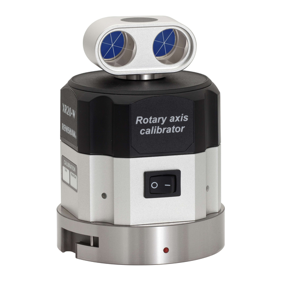
System overview XR20 is a rotary axis calibrator designed for measuring rotary axes . Key features include: • Compatible with Renishaw XL-80 or XM systems . • Compact and lightweight . • Quick and simple mounting system . • Easy alignment with built-in alignment aid . -
Page 13: System Components
System components XR20 Chuck adaptor Centration aid Mounting ring Mounting ring adaptor Battery Li-Polymer × 3 Battery charger www.renishaw.com... -
Page 14: Carto Software Suite
CARTO software suite The XR20 rotary axis calibrator is used with the CARTO software suite which comprises two applications: Capture to collect laser inferometry data and Explore to provide powerful analysis . www .renishaw .com/carto XR20 rotary axis calibrator... - Page 15 The centration aid allows the mounting ring to be easily centred to the axis of rotation of the machine under test before the XR20 rotary axis calibrator is The mounting ring adaptor plate enables the XR20 to be fitted to rotary tables mounted to the machine .
-
Page 16: Setting Up A Test
Ensure that the laser beam can reach the rotary table without obstruction . The XR20 requires a defined test method to be entered into the machine tool controller via a part program . The test method and part program can be generated from the CARTO software . - Page 17 T-slots . If the T-slots do not pass aid from the XR20 kit or by using a dial test indicator (DTI) . The centration under the mounting holes, toe clamps may need to be used . Remove the of the mounting ring should be aligned to the following specification: centration aid .
-
Page 18: Xm System Set-Up
XM system set-up 11 . Switch on the XR20 to check the battery power: a green LED indicates sufficient battery power. Switch off the XR20 to conserve battery Attach the beam blocker to the front of the XM launch unit . - Page 19 Observe the reflected beam on the launch beam blocker. Adjust the pitch of Turn the XR20 optics so that the retroreflectors are pointing towards the the launch so that the reflected beam is on the centre line. laser to within ±2° .
-
Page 20: Xl System Set-Up
Using the machine’s handwheel, raise the interferometer, attached to the F-9908-0683) for more information on the optics mounting kit and angular spindle, in Z only. To maintain alignment between the XR20 and the angular interferometer . interferometer, do not move it in X or Y. - Page 21 . Beam aperture Reflected beam Translate the XL-80 horizontally and vertically so that the laser beam hits the target on the alignment aid as shown: NOTE: The laser may become destabilised; this is not a problem . www.renishaw.com...
- Page 22 Ensure that the beam from the laser is concentric with the white target . Angular interferometer Reduced laser beam Target Beam aperture Detector aperture 14 . Switch on the XR20 and check that the status LEDs go green . XR20 rotary axis calibrator...
-
Page 23: Bluetooth ® Set-Up For Xr20 Rotary Axis Calibrator
Bluetooth set-up for XR20 rotary axis calibrator ® The XR20 rotary axis calibrator communicates with the PC using Bluetooth wireless technology . Before connecting the XR20, Bluetooth capability must be provided on your PC . This can be done either by enabling the PC’s internal Bluetooth device (if available) or by using a proprietary USB Bluetooth dongle recommended by Renishaw . -
Page 24: Bluetooth ® Set-Up For Xr20-W Rotary Axis Calibrator
XR20-W rotary axis calibrator ® Ensure that Bluetooth functionality is switched on (see PC user instructions) . The XR20-W rotary axis calibrator communicates with the PC using Bluetooth Run the CARTO software and connect the XR20 to establish wireless technology . communication . -
Page 25: Feedrate
Feedrate If the target interval is greater than 10°, the XR20 rotary axis calibrator will automatically track the movement of the machine under test . The laser’s beam remains unbroken, as the XR20 angular reflector continues to face the laser as the machine moves . -
Page 26: Different Mounting Configurations
Set-ups 1 to 3 show typical set-up using the fittings supplied with the standard XR20 kit . Always ensure the mounting surface of the table under test and the XR20 facing ring are clean and free of swarf, debris and burrs . Mounting set-up 1 (default configuration) In most applications, the facing ring of the XR20 can be mounted directly to the surface of the axis under test (as shown) using the mounting ring . - Page 27 XR20 mounting ring being mounted securely and parallel to the rotary axis . Mount the XR20 to the axis under test as shown . Mount the adaptor plate to the mounting ring using three M5 × 12 mm countersunk screws .
- Page 28 . NOTE: The orthogonality of the adaptor to the test axis is crucial to capturing ‘clean’ data . Mounting ring Adaptor plate Chuck adaptor Cap head screws M4 ×12 XR20 rotary axis calibrator...
- Page 29 This set-up may be required if it is not possible to mount the laser directly This optical set-up is used when the axis under test has a vertical axis of in front of the XR20 rotary axis calibrator due to machining guarding . In this rotation . See the setting up the hardware section for more details .
- Page 30 . through 90° into the angular interferometer’s input aperture as shown . Refer to the XL laser system user guide (Renishaw part no . F-9908-0683) for more information . CAUTION: Mounting the XM launch to a tripod may result in measurement error .
-
Page 31: Set-Up Errors
Set-up errors Axes of rotation coincident but not parallel When mounting the XR20 rotary axis calibrator and setting up the optics, it Induced error is important to align them as accurately as possible . Small misalignments are expected to exist . This section indicates how tolerant the software is at minimising or eliminating them, and the effect they have on captured data . - Page 32 . In this case, it is recommended that the TIR of the surface the XR20 is to be mounted to is checked (whilst rotating the axis under test) using a dial gauge . This allows alignment to be verified before the test starts.
- Page 33 The angle of E can be calculated within the set-up by measuring the vertical position of beam 2 relative to 1 and then using the comparison table below . Beam aperture Reflected beam Distance between XL80/XM Maximum vertical offset (mm) and XR20 (m) 0 .1 0 .4 0 .2 0 .8 0 .5...
- Page 34 Use alignment aid to align optics perpendicular to laser beam . • Error eliminated by optical set-up calibration cycle . • Caused by thermal expansion and manufacturing tolerances . • Error eliminated by optical set-up calibration cycle . • No danger of beam obstruction . XR20 rotary axis calibrator...
-
Page 35: Diagnostics And Troubleshooting
Replace the battery • If problems persist, contact your local Renishaw office XR20 status LED is slow flashing blue and XR20 and software in power-saving mode • Click on DRO to resume live reading CARTO software DRO (Digital Read Out) is dim Software has not installed in the required The PC’s regional settings are not set to... -
Page 36: Status Leds
. To exit power-saving mode, click on the DRO . The XR20 must be re- referenced before testing can continue . If the XR20 is idle for 5 minutes, it switches off and the status LED goes off . The unit must be switched off, then on again, and re-referenced before testing can continue . -
Page 37: Care And Handling
NOTE: This is 3 years from sale by Renishaw rather than from factory calibration date as stated on the calibration certificates supplied with the new Further reminders are built into the CARTO software . If an XR20 is out of equipment, since the units are stored under controlled conditions by Renishaw calibration, the date of last recalibration and the recommended date for prior to sale . -
Page 38: Calibration Certificate
Certificate content • Place the XR20 mounting ring and adaptor plate into the case when Each certificate is unique and is identified by a certificate number . All XR20 not in use . certificates provide the following key information: •... -
Page 39: Storage And Environmental Specification
. • Do not use in contaminated atmospheres . Defective products should be returned to Renishaw for repair . • Store securely when not in use . There are no user-serviceable parts inside the main calibration system Cleaning recommendations equipment . -
Page 40: System Specification
Resolution 0 .1 arcsec Range 0° to 360° NOTE: To protect against battery damage, the XR20 rotary axis calibrator will Rotary (with XM system) not power up when operated below 0 °C and above 40 °C . Accuracy ±1 .2 arcsec (at 20 °C) Resolution 0 .1 arcsec... - Page 41 28 AWG/2C (for data) 20 AWG/2C Battery life 3 hours typical operation (for new batteries) (for power) Power supply (battery charger and XR20) Technical data: Part no. 56456 702 099 (rechargeable Li-Polymer) USB Plug & Go Battery type Varta EasyPack XL part no . 56456 702 MSDS Ref 099 (rechargeable Li-Polymer), 3 .7 V...
-
Page 42: Power Supply: Xr20
The USB power supply should be used if no charged batteries are available or you are performing a long test . Do not connect the XR20 to a standard PC’s USB port, as the XR20 will not recognise the PC as a suitable power supply and therefore will not turn on . -
Page 43: Power Supply: Rechargeable Battery
Power supply: rechargeable battery To remove a battery, turn the battery cover on the bottom of the XR20 anticlockwise and remove it to reveal the battery compartment . The XR20 rotary axis calibrator kit contains Li-Polymer Varta Easypack batteries and associated charger . These batteries are the only type which should be used with the XR20 unit . - Page 44 . For optimum battery performance, only fit fully-charged batteries. A battery should continue to be used until battery low is indicated by the XR20 status LEDs . Once battery low is indicated, replace the battery with a fully- charged one as soon as possible .
-
Page 45: Weights And Dimensions
Weights and dimensions Description Weight XR20 weight 1 .2 kg XR20 system weight in case 6 .5 kg XR20 Chuck adaptor Ø 101 Ø 60 Ø 40 4 × 80 PCD, C’BORE Ø 9 .2 × 7 DP and Ø5 .5 THRO’... - Page 46 Mounting ring Mounting adaptor Ø 128 PCD Ø 120 PCD Ø 150 4 SLOTS Ø 10 .6 Ø 80 PCD Ø 150 Ø 60 Ø 60 Ø 96 4 POSN’S M5 THRO’ XR20 rotary axis calibrator...
- Page 47 +44 (0) 1453 524524 uk@renishaw.com © 2019–2022 Renishaw plc . All rights reserved . This document may not be copied or reproduced in whole or in part, or transferred to any other WHILE CONSIDERABLE EFFORT WAS MADE TO VERIFY THE ACCURACY OF THIS media or language by any means, without the prior written permission of Renishaw .
Need help?
Do you have a question about the XR20 and is the answer not in the manual?
Questions and answers