Table of Contents
Advertisement
Advertisement
Table of Contents

Related Manuals for Renishaw OMP60


Summary of Contents for Renishaw OMP60
- Page 1 Installation guide H-4038-8505-03-B OMP60 – optical machine probe...
- Page 2 This document may not be copied or reproduced in whole or in part, or transferred to any other media or language, by any means, without the prior written permission of Renishaw plc. Renishaw plc. Registered in England and Wales. Company no: 1106260. Registered office: New Mills, Wotton-under-Edge, Gloucestershire, GL12 8JR, UK.
-
Page 3: Table Of Contents
OMP60 software notices ........ - Page 4 Performance envelope of OMM-2C with OMP60 ....... . . 3.4...
-
Page 5: Before You Begin
Renishaw office. Renishaw warrants its equipment and software for a limited period (as set out in the Standard Terms and Conditions), provided that they are installed and used exactly as defined in associated Renishaw documentation. -
Page 6: Cnc Machines
Care of the probe Keep system components clean and treat the probe as a precision tool. Patents Features of the OMP60 probe, and other similar Renishaw probes, are subject of one or more of the following patents and/or patent applications: CN 100416216... -
Page 7: Intended Use
To reduce the risk of shipment delays, should you need to return this product to Renishaw for any reason, do not return any batteries. In all applications involving the use of machine tools, eye protection is recommended. - Page 8 The product was evaluated and classified using the following standard: BS EN 62471:2008 The photobiological safety of lamps and lamp systems. Renishaw recommends that you do not stare at or look directly into any LED device, irrespective of its risk classification.
-
Page 9: Omp60 Basics
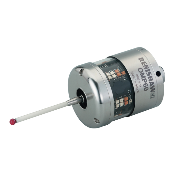
OMP60 basics Introduction The OMP60 is an optical machine tool probe suitable for use on medium to large machining and multi- tasking centres. It is designed to resist optical interference, false triggering and shock. The OMP60 can be operated in either ‘Legacy’ or ‘Modulated’ optical transmission modes – see probe settings for further details. -
Page 10: System Interface
The OMI-2T receiver / interface or OMM-2 receiver with OSI or OSI-D interfaces are the recommended interfaces for use with the OMP60 as they provide substantially increased resistance to light interference whilst providing the user greater flexibility to operate a multiple probe system. -
Page 11: Configurable Settings
Optical on / Optical off Optical on / Timer off Spin on / Spin off Spin on / Timer off Shank switch on / Shank switch off OMP60 switch-on method OMP60 switch-off method Switch-on time Switch-on options are configurable Switch-off options are configurable... -
Page 12: Enhanced Trigger Filter
It may be necessary to revise the probe program software to allow for the increased activation time. Modulated mode The OMP60 becomes compatible for use with the OMM-2 or OMM-2C receiver with OSI or OSI-D interface or with an OMI-2 / OMI-2T / OMI-2H / OMI-2C receiver / interface to provide substantially increased resistance to light interference. -
Page 13: Optical Power
Optical power Where the separation between the OMP60 and the OMI-2 / OMI-2T / OMI-2H / OMI-2C / OMM with MI 12 or OMM-2 with OSI or OSI-D is small, low optical power may be used. In this setting, the optical transmission range will be reduced as shown on the performance envelopes so that battery life will be extended. -
Page 14: Omp60 Specification
OMP60 installation guide OMP60 specification Principal application Workpiece inspection and job set-up on medium to large-sized machining centres and multi-tasking centres. Dimensions Length 76 mm (2.99 in) Diameter 63 mm (2.48 in) Weight (without shank) With batteries 885 g (31.22 oz) Without batteries 836 g (29.49 oz) - Page 15 Environment IP rating IPX8 (BS EN 60529:1992+A2:2013) Storage temperature −25 °C to +70 °C (−13 °F to +158 °F) Operating temperature +5 °C to +55 °C (+41 °F to +131 °F) Battery types 2 x AA 1.5 V alkaline or 2 x AA 3.6 V Lithium Thionyl Chloride (LTC) Battery reserve life Approximately one week after a low battery warning is first given.
-
Page 16: Typical Battery Life
OMP60 installation guide Typical battery life Modulated transmission 2 x AA 1.5V Optical on/off Shank on/off Spin on/off alkaline Standard Standard Standard batteries power power power power power power (typical) Standby 818 days 940 days 304 days 5% usage 134 days... -
Page 17: System Installation
OMP60 on one machine are not received by the receiver on the other machine, and vice versa. When this is the case it is recommended that the OMP60 low optical power is used and that the low range setting is used on the receiver. -
Page 18: Performance Envelope When Using The Omp60 With An Omm-2 / Omi-2T / Omi-2H / Omi-2 (Modulated Transmission)
The probe and OMM-2 / OMI-2T / OMI-2H / OMI-2 diodes must be in each other's field of view and within the performance envelope shown. The OMP60 performance envelope is based on the OMM-2 / OMI-2T / OMI-2H / OMI-2 being at 0° and vice versa. -
Page 19: Installing The Omp60 With An Omm-2C Receiver With Osi Or Osi-D Interface
CAUTION: If two systems are operating in close proximity to each other, take care to ensure that the signals transmitted from the OMP60 on one machine are not received by the receiver on the other machine, and vice versa. When this is the case, it is recommended that the OMP60 low optical power is used. -
Page 20: Performance Envelope Of Omm-2C With Omp60
(eye-to-eye). In multiple probe mode applications, OMP60 may be configured as Probe 1, Probe 2 or Probe 3. CAUTION: If two systems are operating in close proximity, take care to ensure that the signals transmitted from the OMP60 on one machine are not received by the OMM-2C on another machine and vice versa. -
Page 21: Performance Envelope When Using The Omp60 With An Omi (Legacy Transmission)
Performance envelope when using the OMP60 with an OMI (legacy transmission) The probe and OMI diodes must be in each other's field of view, and within the performance envelope shown. The OMP60 performance envelope is based on the OMI being at 0° and vice versa. 75°... -
Page 22: Preparing The Omp60 For Use
OMP60 installation guide Preparing the OMP60 for use Fitting the stylus 1.8 Nm – 2.2 Nm (1.3 lbf.ft – 1.6 lbf.ft) M-5000-3707... - Page 23 NOTE: Must be used with steel styli. For optimum metrology performance do not use a weak link with ceramic or carbon fibre styli. Fitting a stylus with a weak link onto the OMP60 In the event of excessive stylus overtravel, the weak link is designed to break, thereby protecting the probe from damage.
-
Page 24: Installing The Batteries
OMP60 installation guide Installing the batteries NOTES: See Section 5 – “Maintenance” for a list of suitable battery types. Ensure the product is clean and dry before inserting batteries. Do not allow coolant or debris to enter the battery compartment. -
Page 25: Mounting The Probe On A Shank (Or Machine Table)
Mounting the probe on a shank (or machine table) NOTE: In instances where the OMP60 is to be used with a shank switch, it will be necessary to remove the plug from the rear of the probe using pliers. This should then be substituted with the bobbin (A-4038-0303). -
Page 26: Stylus On-Centre Adjustment
OMP60 installation guide Stylus on-centre adjustment NOTES: During adjustment, care must be taken not to rotate the probe relative to the shank, as damage to the bobbin (A-4038-0303) can occur where fitted. If a probe and shank assembly is dropped, it must be rechecked for correct on-centre adjustment. -
Page 27: Stylus Trigger Force And Adjustment
Spring force within the probe causes the stylus to sit in a unique position and return to this position following each stylus deflection. Stylus trigger force is set by Renishaw. The user should only adjust the trigger force in special circumstances, e.g. where there is excessive machine vibration or insufficient force to support the stylus weight. -
Page 28: Calibrating The Omp60
OMP60 installation guide Calibrating the OMP60 Why calibrate a probe? A spindle probe is just one component of the measurement system which communicates with the machine tool. Each part of the system can introduce a constant difference between the position that the stylus touches and the position that is reported to the machine. -
Page 29: Calibrating In A Ring Gauge Or On A Datum Sphere
Calibrating in a ring gauge or on a datum sphere Calibrating a probe either in a ring gauge or on a datum sphere with a known diameter automatically stores one or more values for the radius of the stylus ball. The stored values are then used automatically by the measuring cycles to give the true size of the feature. - Page 30 OMP60 installation guide 3.14 This page is intentionally left blank.
-
Page 31: Trigger Logic
Trigger Logic™ Reviewing the probe settings LED check > 5 s Key to the symbols LED short flash LED long flash × Switch-on method Optical on Shank on Spin on Switch-off method (omitted for shank on) Optical off or Short timeout Medium timeout Long timeout Spin off... -
Page 32: Probe Settings Record
On (20 ms) On (40 ms) Optical transmission Legacy (start filter off) method Legacy (start filter on) Modulated PROBE 1 Modulated PROBE 2 Modulated PROBE 3 Optical power Standard Factory settings are for kit (A-4038-2001) only. OMP60 serial no ........ - Page 33 This page is intentionally left blank.
-
Page 34: Changing The Probe Settings
OMP60 installation guide Changing the probe settings Insert the batteries or, if they have already been > 5 s installed, remove them for five seconds and then refit them. Following the LED check, immediately deflect the stylus and hold it deflected until five red flashes have been observed (if the battery power is low ×... - Page 35 Enhanced trigger filter setting 0 ms 10 ms 20 ms 40 ms Optical transmission method Legacy Legacy Modulated Modulated Modulated (start filter off) (start filter on) PROBE 1 PROBE 2 PROBE 3 Optical power Standard Return to “Switch-on method” New settings complete...
-
Page 36: Operating Mode
OMP60 installation guide Operating mode LEDs LEDs LEDs flashing flashing flashing green Probe status LEDs LED colour Probe status Graphic hint Flashing green Probe seated in operating mode Flashing red Probe triggered in operating mode Flashing green and blue Probe seated in operating mode – low battery Flashing red and blue Probe triggered in operating mode –... -
Page 37: Maintenance
Wipe the window of the probe with a clean cloth to remove machining residue. This should be done on a regular basis to maintain optimum transmission. CAUTION: The OMP60 has a glass window, handle with care if broken to avoid injury. -
Page 38: Changing The Batteries
OMP60 installation guide Changing the batteries CAUTIONS: Do not leave dead batteries in the probe. When changing batteries, do not allow coolant or debris to enter the battery compartment. When changing batteries, check that the battery polarity is correct. Take care to avoid damaging the battery cassette gasket. - Page 39 NOTES: After removing the old batteries, wait more than 5 seconds before inserting the new batteries. Do not mix new and used batteries or battery types, as this will result in reduced life and damage to the batteries. Always ensure that the cassette gasket and mating surfaces are clean and free from dirt before reassembly.
-
Page 40: Diaphragm Replacement
OMP60 installation guide Diaphragm replacement OMP60 diaphragms The probe mechanism is protected from coolant and debris by two diaphragms. These provide adequate protection under normal working conditions. You should periodically check the outer diaphragm for signs of damage. If this is evident, replace the outer diaphragm. -
Page 41: Omp60M System
OMP60M system OMP60M system OMP60M is a special modular version of OMP60. It enables probe inspection of part features inaccessible to OMP60, by fitting selected adaptors and extensions as shown below. See Chapter 8 – “Parts list”. NOTE: Maximum spindle speed 750 rev/min. -
Page 42: Omp60M Dimensions
OMP60 installation guide OMP60M dimensions 50.50 100/150/200 67.25 (2.65) (1.99) (3.94/5.91/7.88) 12.50 (0.49) 40.75 50/100/150 (1.60) (1.97/3.94/5.91) 67.25 (2.65) Dimensions given in mm (in) OMP60M screw torque values 10 Nm to 12 Nm (7.37 lbf.ft to 8.85 lbf.ft) 2.6 Nm (1.92 lbf.ft) -
Page 43: Fault-Finding
Probe out of range / not aligned Check configuration and alter as with receiver. required. Transmission beam obstructed. Check OMP60 and receiver windows are clean and remove any obstruction. No receiver start signal. Check start signal by reviewing receiver LED. - Page 44 OMP60 installation guide Symptom Cause Action Probe fails to switch on Wrong switch-on mode is Reconfigure to shank-on mode. (shank-on is required). selected. Dead batteries. Change batteries. Unsuitable batteries. Change batteries. Batteries inserted incorrectly. Check battery insertion. Malfunctioning shank switch.
- Page 45 Symptom Cause Action Probe crashes. Inspection probe using tool setting When two systems are active, probe signals. isolate tool setting probe. Workpiece obstructing probe path. Review probing software. Adjacent probe. Reconfigure to low power mode and reduce range of receiver. Probe length offset missing.
- Page 46 OMP60 installation guide Symptom Cause Action Probe fails to switch off Wrong switch-off mode selected. Reconfigure to optical-off mode. (optical-off is required). Optical / magnetic interference. Check for interfering lights or motor. Probe is inadvertently switched Check position of receiver.
-
Page 47: Parts List
Part Description number OMP60 A-4038-0001 OMP60 probe with batteries, tools and support card (set to optical on / optical off) – legacy transmission. OMP60 A-4038-0002 OMP60 probe with batteries, tools and support card (set to optical on / time off 134 sec) – legacy transmission. - Page 48 OMP60 installation guide Type Part Description number OSI interface A-5492-2000 OSI (multiple probe mode) with DIN rail mounting, terminal block and support card. OSI interface A-5492-2010 OSI (single probe mode) with DIN rail mounting, terminal block and support card. OSI-D interface...
- Page 49 Type Part Description number Publications. These can be downloaded from our website at www.renishaw.com OMP60 H-4038-8505 Installation guide: for set-up of the OMP60. OMI-2 H-5191-8504 Installation guide: for set-up of the OMI-2. OMI-2T H-5439-8510 Installation guide: for set-up of the OMI-2T.
- Page 50 Renishaw plc +44 (0)1453 524524 +44 (0)1453 524901 New Mills, Wotton-under-Edge uk@renishaw.com Gloucestershire, GL12 8JR United Kingdom www.renishaw.com For worldwide contact details, visit www.renishaw.com/contact © 2008 – 2022 Renishaw plc Issued 12.2022 Part no. H-4038-8505-03-B...
Need help?
Do you have a question about the OMP60 and is the answer not in the manual?
Questions and answers