Table of Contents
Advertisement
Quick Links
Advertisement
Table of Contents

Related Manuals for GIGAIPC mITX-1505A


Summary of Contents for GIGAIPC mITX-1505A
-
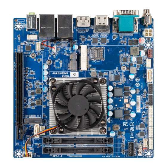
Page 1: Mini-Itx Motherboard
(MRZNRMI) Mini-ITX Motherboard User’s Manual 1st Ed www.gigaipc.com... -
Page 2: Copyright Notice
While reasonable efforts have been made in the preparation of this document to assure its accuracy, GIGAIPC assumes no liabilities resulting from errors or omissions in this document, or from the use of the information contained herein. -
Page 3: Acknowledgement
Core, Atom are trademarks of Intel Corporation • • ITE is a trademark of Integrated Technology Express, Inc. IBM, PC/AT, PS/2, and VGA are trademarks of International Business • Machines Corporation. All other product names or trademarks are properties of their respective owners. www.gigaipc.com... -
Page 4: Packing List
Before setting up your product, please make sure the following items have been shipped: Item Quantity mITX-1505A MB SATA power cable I/O Bracket If any of these items are missing or damaged, please contact your distributor or sales representative immediately. -
Page 5: About This Document
(if any), its specifications, dimensions, jumper/ connector settings/definitions, and driver installation instructions (if any), to facilitate users in setting up their product. Users may refer to the GIGAIPC.com for the latest version of this document. www.gigaipc.com... -
Page 6: Safety Precautions
Make sure the device is installed near a power outlet and is easily accessible. 10. Keep this device away from humidity. 11. Place the device on a solid surface during installation to prevent falls 12. Do not cover the openings on the device to ensure optimal heat dissipation. www.gigaipc.com... - Page 7 18. D O N O T L E AV E T H I S D E V I C E I N A N U N C O N T R O L L E D ENVIRONMENT WITH TEMPERATURES BEYOND THE DEVICE’S PERMITTED STORAGE TEMPERATURES (SEE CHAPTER 1) TO PREVENT DAMAGE. www.gigaipc.com...
-
Page 8: Fcc Statement
Il y a un risque d’explosion si la batterie est remplacée de façon incorrecte. Ne la remplacer qu’avec le même modèle ou équivalent recommandé par le constructeur. Recycler les batteries usées en accord avec les instructions du fabricant et les directives gouvernementales de recyclage. www.gigaipc.com... -
Page 9: China Rohs Requirements (Cn)
China RoHS Requirements (CN) 产品中有毒有害物质或元素名称及含量 GIGAIPC Main Board/ Daughter Board/ Backplane 有毒有害物质或元素 部件名称 铅 汞 镉 六价铬 多溴联苯 多溴二苯醚 (Pb) (Hg) (Cd) (Cr(VI)) (PBB) (PBDE) 印刷电路板 及其电 ○ ○ ○ ○ ○ ○ 子组件 外部信号 连接器 ○ ○ ○ ○... -
Page 10: China Rohs Requirement (En)
China RoHS Requirement (EN) Poisonous or Hazardous Substances or Elements in Products GIGAIPC Main Board/ Daughter Board/ Backplane Poisonous or Hazardous Substances or Elements Component Hexavalent Polybrominated Polybrominated Lead Mercury Cadmium Chromium Biphenyls Diphenyl Ethers (Pb) (Hg) (Cd) (Cr(VI)) (PBB) (PBDE) PCB &... -
Page 11: Table Of Contents
2.2.5 DP (Display port) ............26 2.2.6 USB3_LAN1, USB3_LAN2 (USB+LAN connector x 2) ..27 2.2.7 DC_IN2 (ATX 2x2 pin power connector) ....... 28 2.2.8 SYS_FAN (System Fan connector) ......... 29 2.2.9 SATAPW0, SATAPW1 (SATA power connector) ..... 30 www.gigaipc.com... - Page 12 2.2.27 M2E (M.2 Slot, E-key NGFF 2230) ......... 48 2.2.28 CLR_CMOS (Clear CMOS jumper) ......... 49 2.2.29 MPCIE (Mini PCIE connector) ........50 Chapter 3 – BIOS Introduction ..............52 The Main Menu............. 53 Advanced ..............54 3.3.1 TPM Configuration ............55 www.gigaipc.com...
- Page 13 3.3.5 Network Stack Configuration ........59 3.3.6 S5 RTC Wake Settings ........... 60 3.3.7 SATA Configuration ............61 3.3.8 Digital IO Port Configuration ........62 Chipset ................63 Security ................. 64 Boot ................67 Save & Exit ..............68 www.gigaipc.com...
-
Page 14: Chapter 1 - Product Specifications
Chapter 1 Chapter 1 – Product Specifications www.gigaipc.com... - Page 15 1.60 31.61 179.7 20.55 37.01 4.90 132.08 154.94 www.gigaipc.com...
-
Page 16: Specifications
Specifications Motherboard mITX-1505A (MRZNRMI) Mini-ITX Form Factor 170W x 170D (mm) AMD Ryzen™ R1505G Embedded Processor with Radeon™ Vega 3 Graphics 2 cores, 4 threads, 2.4GHz, up to 3.3GHz TDP 25W Socket 1 x FP5 Type 1 Chipset 2 x DDR4 SO-DIMM sockets, Max. Capacity 32 GB... - Page 17 Motherboard mITX-1505A (MRZNRMI) 1 x 4-pin ATX main power connector 2 x SATA power connectors 1 x CPU fan header 1 x System fan header 1 x Front panel header 1 x Front panel audio header 1 x 2W Speaker out header...
-
Page 18: Chapter 2 - Hardware Information
Chapter 2 Chapter 2 – Hardware Information www.gigaipc.com... -
Page 19: Jumpers And Connectors
Jumpers and Connectors www.gigaipc.com... - Page 20 USB 2.0 header F_USB2_2 COM3, COM4, COM Port (RS-232) COM5 15 GPIO_CNT General Purpose input/output header 16 CCTALK ccTalk header 17 CC_PWR ccTalk power jumper 18 SYS_PANEL Front panel header 19 TPM_LPC TPM header 20 CI Chassis Intrusion detect header www.gigaipc.com...
- Page 21 25 M2M M.2 Slot, M-Key NGFF 2280 26 SPK_OUT Speaker out connector 27 F_AUDIO Front panel audio header 28 BAT Battery connector 29 M2E M.2 Slot, E-Key NGFF 2230 30 CLR_CMOS Clear CMOS jumper 31 MPCIE MINI PCIE connector www.gigaipc.com...
-
Page 22: Io Connector Information
DC IN Jack connector 2 COM1_2 COM Port (RS-232) 3 HDMI_21 HDMI connector Display ports 4 DP 5 USB3_LAN1 LAN Connector x 2 USB3_LAN2 USB 3.2 Gen 1 Connector x 4 Line Out port (Green) AUDIO Mic In port (Pink) www.gigaipc.com... -
Page 23: Dc_In1 (Dc In Jack Connector)
2.2.2 DC_IN1 (DC IN Jack connector) DC In Jack connector Connector PN Vendor 655-360-000 SHEN-MING www.gigaipc.com... -
Page 24: Com1_2 (Com Port (Rs-232))
2.2.3 COM1_2 (COM Port (RS-232)) Serial Port connector Connector PN Vendor D20HB1102002P6JN FENYING Pin No. Definition www.gigaipc.com... -
Page 25: Hdmi_21 (Hdmi Connector)
2.2.4 HDMI_21 (HDMI connector) Connector PN Vendor HDMI Connector QJ11191-DFB1-4F FOXCONN Pin No. Definition Pin No. Definition TX2p CLKn TX2n TX1p TX1n TX0p Hot Plug TX0n Detect CLKp www.gigaipc.com... -
Page 26: Dp (Display Port)
2.2.5 DP (Display port) DP connector Connector PN Vendor 3VD11207-D7AB-4H FOXCONN Pin No. Definition Pin No. Definition TX0p TX3n TX0n TX1p AUXp TX1n TX2p AUXn Hot Plug Detect TX2n TX3p 3.3V www.gigaipc.com... -
Page 27: Usb3_Lan1, Usb3_Lan2 (Usb+Lan Connector X 2)
Pin No. Definition Pin No. Definition Definition Definition BI_DA+ BI_DC- BI_DA- BI_DB- BI_DB+ BI_DD+ BI_DC+ BI_DD- State Description USB3_RX1n USB3_RX2n Orange On 1Gbps data rate USB3_RX1p USB3_RX2p Green On 100Mbps data rate USB3_TX1n USB3_TX2n 10Mbps data rate USB3_TX1p USB3_TX2p www.gigaipc.com... -
Page 28: Dc_In2 (Atx 2X2 Pin Power Connector)
2.2.7 DC_IN2 (ATX 2x2 pin power connector) Pin 1 Power connector Connector PN Vendor 740-81-04TW56 PINREX Pin No. Definition +12V +12V www.gigaipc.com... -
Page 29: Sys_Fan (System Fan Connector)
2.2.8 SYS_FAN (System Fan connector) Pin 1 System FAN connector Connector PN Vendor 744-81-045R11 PINREX WF04R22RJQ105 HORNGTONG Pin No. Definition Detect Speed Control www.gigaipc.com... -
Page 30: Satapw0, Satapw1 (Sata Power Connector)
2.2.9 SATAPW0, SATAPW1 (SATA power connector) Pin 1 Pin 1 Hard Disk Power connector Connector PN Vendor 743-81-04TW00 PINREX Pin No. Definition www.gigaipc.com... -
Page 31: Sata0, Sata1 (Sata 6Gb/S Connector)
※NOT E : M.2 M - Key and S ATA0 p or t share the same signal. When installing the Pin No. Definition storage on M.2 M-Key slot and SATA0 port at the same time, only M.2 storage will be detected. www.gigaipc.com... -
Page 32: F_Usb2_1, F_Usb2_2 (Usb 2.0 Header)
2.2.11 F_USB2_1, F_USB2_2 (USB 2.0 header) Pin 1 USB 2.0 header Connector PN Vendor 210-92-05GB04 PINREX PH10R53BAZ009 HORNGTONG Pin No. Definition No Pin No Connect www.gigaipc.com... -
Page 33: Com3, Com4, Com5 (Com Header (Rs-232))
2.2.12 COM3, COM4, COM5 (COM header (RS-232)) Pin 1 Serial Port Cable Connector Connector PN Vendor 725-81-10TW00 PINREX A2004WV-2X05P46 JOINT-TECH Definition Pin Definition No Connect www.gigaipc.com... -
Page 34: Gpio_Cnt (General Purpose Input/Output Connector)
2.2.13 GPIO_CNT (General purpose input/output connector) Pin 1 GPIO Connector Pin No. Definition SMBus DATA Connector PN Vendor Pin No. Definition 725-81-12TW00 PINREX GPIO-output_1 A2004WV-2X06P46 JOINT-TECH GPIO-input_1 GPIO-output_2 GPIO-input_2 GPIO-output_3 GPIO-input_3 GPIO-output_4 GPIO-input_4 SMBus Clock www.gigaipc.com... -
Page 35: Cctalk (Cctalk Header)
2.2.14 CCTALK (ccTalk header) Pin 1 ccTalk Connector Connector PN Vendor 721-81-045W00 PINREX A2001WV-04P146 JOINT-TECH Pin No. Definition 5V/12V (Default 5V) DATA (5V Level) www.gigaipc.com... -
Page 36: Cc_Pwr (Cctalk Power Jumper)
2.2.15 CC_PWR (ccTalk power jumper) Pin 1 ccTalk power jumper Connector PN Vendor 220-96-03GB01 PINREX PH03N2-7BAN000 HORNGTONG Pin No. Definition ccTalk_Power Jumper setting 1-2 Close : 5V. (Default setting) 2-3 Close : 12V. www.gigaipc.com... -
Page 37: Sys_Panel (Front Panel Header)
2.2.16 SYS_PANEL (Front Panel Header) Pin 1 System Panel Header Connector PN Vendor 210-92-05GW5W PINREX Pin No. Definition HDD LED+ Power LED+ HDD LED- Power LED- Power Button+ Reset Button Power Button- No Connect No Pin www.gigaipc.com... -
Page 38: Tpm_Lpc (Tpm Header)
2.2.17 TPM_LPC (TPM header) Pin 1 TPM Module Connector Pin No. Definition LAD3 LFRAME Pin No. Definition Connector PN Vendor LPCCLK 3.3V 52S-90-14GB10 PINREX TPM RST BH14NQ-7BAI010 HORNGTONG 3.3V LAD0 IRQ_SERIAL LAD1 TPM_DET LAD2 www.gigaipc.com... -
Page 39: Ci (Chassis Intrusion Detect Header)
2.2.18 CI (Chassis Intrusion detect header) Pin 1 Chassis instrusion detect header Pin No. Definition Signal www.gigaipc.com... -
Page 40: At_Cn (At/Atx Mode Select Jumper)
2.2.19 AT_CN (AT/ATX mode select jumper) Pin 1 AT/ATX mode select jumper Connector PN Vendor 220-96-03GB01 PINREX PH03N2-7BAN000 HORNGTONG Pin No. Definition AT MODE Detect ATX MODE Jumper setting 1-2 Close : AT mode. 2-3 Close : ATX mode. (Default setting) www.gigaipc.com... -
Page 41: Sodimm1, Sodimm2 (2 X Ddr4 So-Dimm Slots)
2.2.20 SODIMM1, SODIMM2 (2 x DDR4 SO-DIMM slots) www.gigaipc.com... -
Page 42: Cpu_Fan (Cpu Fan Connector)
2.2.21 CPU_FAN (CPU Fan connector) Pin 1 CPU FAN connector Connector PN Vendor 744-81-045W1Z PINREX Pin No. Definition Detect Speed Control www.gigaipc.com... -
Page 43: Pciex4 (Pcie X16 (Gen3 X4) Slot)
2.2.22 PCIEX4 (PCIE x16 (Gen3 x4) slot) PCIEX16 connector www.gigaipc.com... -
Page 44: M2M (M.2 Slot, M-Key Ngff 2280)
Connector PN Vendor 80159-8521 BELLWETHER ※NOTE : M.2 M-Key and SATA0 port share the same signal. When installing the storage on M.2 M-Key slot and SATA0 port at the same time, only M.2 storage will be detected. DEVSLP SMB Clock www.gigaipc.com... -
Page 45: Spk_Out (Speaker Out Connector)
2.2.24 SPK_OUT (Speaker out connector) Pin 1 Audio Amplifie Connector Connector PN Vendor 721-81-045W00 PINREX A2001WV-04P146 JOINT-TECH Pin No. Definition Speaker Out R+ Speaker Out R- Speaker Out L- Speaker Out L+ www.gigaipc.com... -
Page 46: F_Audio (Front Panel Audio Header)
2.2.25 F_AUDIO (Front panel audio header) Pin 1 Front panel audio header Connector PN Vendor 725-81-10TW00 PINREX A2004WV-2X05P46 JOINT-TECH Definition Pin Definition MIC_Left Detect FAUDIO_JD MIC_Right No Connect Detect HPOUT_L HPOUT_R Detect www.gigaipc.com... -
Page 47: Bat (Battery Connector)
2.2.26 BAT (Battery connector) Pin 1 Battery Cable Connector Connector PN Vendor 85205-0270L ACES A1250WV-S-02PC JOINT-TECH Pin No. Definition www.gigaipc.com... -
Page 48: M2E (M.2 Slot, E-Key Ngff 2230)
PCIE CLOCKp PCIE CLOCKn SUSCLK PCIE Clock Pin No. Definition Pin No. Definition PCIRST Request 3.3V PCIE wake up BT_Disable 3.3V WLAN_DISABLE 3.3V 3.3V Connector PN Vendor Pin No. Definition Pin No. Definition 80152-8521 BELLWETHER APCI0095-P002A LOTES PCIE_TXp PCIE_TXn www.gigaipc.com... -
Page 49: Clr_Cmos (Clear Cmos Jumper)
2.2.28 CLR_CMOS (Clear CMOS jumper) Pin 1 Clear COMS Jumper Connector PN Vendor 220-96-03GB01 PINREX PH03N2-7BAN000 HORNGTONG Pin No. Definition RTCVDD_C No Connect 1-2 Close: Clear COMS data. 2-3 Close: Normal Operator (Default setting) www.gigaipc.com... -
Page 50: Mpcie (Mini Pcie Connector)
USB Dp Pin No. Definition Pin No. Definition 3.3V PCIE WAKE 3.3V 3.3V PCIE Clock Request SIM PWR SIM DATA PCIE Clock n SIM Clock PCIE Clock p SIM Reset 3.3V UIM VPP3 Connector PN Vendor AS0B221-S99Q-7H FOXCONN WLAN_DISABLE Reset www.gigaipc.com... -
Page 51: Chapter 3 - Bios
Chapter 3 Chapter 3 – BIOS www.gigaipc.com... -
Page 52: Introduction
Execute command or enter the submenu Increase the numeric value or make + changes Decrease the numeric value or make – changes General Help Previous Values Load Optimized Defaults Settings Save changes & Exit the BIOS Setup program Exit the BIOS Setup program www.gigaipc.com... -
Page 53: The Main Menu
Shows the total memory size of the installed memory Set the Date for the system System Date (Format : Week - Month - Day - Year) Set the time for the system System Time (Format : Hour - Minute - Second) www.gigaipc.com... -
Page 54: Advanced
Advanced The Advanced menu is to configure the functions of hardware settings through submenu. Use arrow keys to move among the items, and press <Enter> to access into the related submenu. www.gigaipc.com... -
Page 55: Tpm Configuration
Pending operation : Trusted Computing None : No execution will be conducted (Default setting) TPM clear : Set to clear data on TPM Physical Presence Spec Version : Choose PPI spec version Option items : 1.2 or 1.3 (Default setting) www.gigaipc.com... -
Page 56: It8786 Super Io Configuration
Serial Port 6 Enabled : Enables allows you to configure the serial port settings Configuration Disabled : if Disabled, displays no configuration for the serial port Device settings : Display the specified Serial Port base I/O address and IRQ www.gigaipc.com... -
Page 57: Hardware Monitor
Enabled : having warning message when the chassis is opened Clear : to clear the warning message on post screen System Shows current CPU temperature temperature CPU temperature Shows current system temperature CPU Fan Speed Shows current CPU Fan speed System Fan Speed Shows current system fan speed www.gigaipc.com... -
Page 58: Cpu Configuration
Command CPU to enter into low power consumption mode when CPU is under Global C-state idle mode. Control Enabled : Enables Global C-states Control (Default setting) Disabled : Disables Global C-states Control Node 0 Information Shows AMD CPU information www.gigaipc.com... -
Page 59: Network Stack Configuration
When Network stack is enabled : Ipv4 PXE Support Disabled : Disables Ipv4 PXE Support Enabled : Enables Ipv4 PXE Support When Network stack is enabled : Ipv6 PXE Support Disabled : Disables Ipv6 PXE Support Enabled : Enables Ipv6 PXE Support www.gigaipc.com... -
Page 60: S5 Rtc Wake Settings
Enable or Disable System to wake on a specific time. Wake system Disabled : Disables system to wake on a specific time (Default setting) from S5 Fixed Time : Enables system to wake on a specific time (Format : hr : min : sec) www.gigaipc.com... -
Page 61: Sata Configuration
3.3.7 SATA Configuration www.gigaipc.com... -
Page 62: Digital Io Port Configuration
Enabled : If Digital IO Output value/level is modified in OS, they will be memorized and kept. SOGPO_1 (Pin 1) SOGPI_1 (Pin 2) SOGPO_2 (Pin 3) SOGPI_2 (Pin 4) Configure Digital IO Input or Output values for each pin. SOGPO_3 (Pin 5) SOGPI_3 (Pin 6) SOGPO_4 (Pin 7) SOGPI_4 (Pin 8) www.gigaipc.com... -
Page 63: Chipset
Power off : Do not power on when the power is back (Default setting) Last state : Restore the system to the state before power loss occures Watchdog timer Enable/Disable Watchdog Timer function Value Option items : Disabled (Default setting), 30 Seconds, 60 Seconds www.gigaipc.com... -
Page 64: Security
To set up Administrator's password Administrator Minimum length : 3 Password Maximum length : 20 To set up User's password User Password Minimum length : 3 Maximum length : 20 Secure Boot Press <Enter> to configure the advanced items www.gigaipc.com... - Page 65 No : Cancel to restore factory settings Reset To Setup Yes : Agree to setup mode Mode No : Cancel to setup mode Enables expert users to modify Secure boot policy variables without full Key Management authentication Press <Enter> to configure the advanced items www.gigaipc.com...
- Page 66 'UEFI CA' from database from DB No : Cancel to remove 'UEFI CA' from database Restore DB variables to fac tor y Restore DB defaults defaults Yes : Agree to restore DB defaults No : Cancel to restore DB defaults www.gigaipc.com...
-
Page 67: Boot
Enabled : Enables Full screen LOGO Show on POST screen LOGO Show Disabled : Disables Full screen LOGO Show on POST screen (Default setting) Shows the information of the storage that be installed in the system Boot Option #1 Choose/set the boot priority www.gigaipc.com... -
Page 68: Save & Exit
Yes : Agree to discard changes and reset and Reset No : Cancel to discard changes and reset Restore/Load default values for all the setup options Restore Defaults Yes : Agree to load optimized defaults No : Cancel to load optimized defaults Boot Override Boot override www.gigaipc.com...
Need help?
Do you have a question about the mITX-1505A and is the answer not in the manual?
Questions and answers