Table of Contents
Advertisement
Quick Links
Advertisement
Table of Contents

Related Manuals for Datalogic DL8700


Summary of Contents for Datalogic DL8700
- Page 1 DL8700 Installation and Operator’s Manual...
- Page 3 DL8700 Installation and Operator’s Manual...
- Page 4 ALL RIGHTS RESERVED Datalogic reserves the right to make modifications and improvements without prior notification. Datalogic shall not be liable for technical or editorial errors or omissions contained herein, nor for incidental or consequential damages resulting from the use of this material.
-
Page 5: Table Of Contents
Quick Start ........................1 Components .......................2 The Half-Screen Display .....................3 Controls and Connectors ....................3 Keyboards........................3 Key Maps........................4 DOS Key Functions Not Available on the DL8700............5 Keyboard LEDs......................5 1.9.1 CAPS LED ........................6 1.9.2 Secondary Keys LED ....................6 1.9.3 Status LED........................6 1.10 Control Keys .......................7 1.11... - Page 6 Laser Barcode Scanner Warnings................30 Enter Data.........................31 3.9.1 Keyboard Entry ......................31 3.9.2 Scanner Entry ......................31 KEY MAPS .......................33 Keypads........................33 Key Map 101 - Key Equivalencies................33 IBM 5250 and TN5250 Terminal Emulator Keypad ...........37 REGULATORY NOTICES ..................38 FCC Compliance.......................38 RF Safety Notice.......................38 Radio Compliance.....................38 Information for the User ....................39 Vehicle Power Supply Connection Safety Statement ..........42...
-
Page 7: Introduction
Use this guide as you would any other source book - reading portions to learn about the DL8700, and then referring to it when you need more information about a particular subject. This guide takes you through installation and operation of the DL8700. -
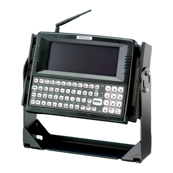
Page 8: Components
DL8700 The DL8700 should be mounted in an area in the vehicle where it: • Does not obstruct the vehicle operator's vision or safe vehicle operation. • Will be protected from rain or inclement weather. • Will be protected from extremely high concentrations of dust or wind-blown debris. -
Page 9: The Half-Screen Display
1.5 CONTROLS AND CONNECTORS Most external connectors for the DL8700 are located on the bottom of the unit. COM 1 connects to a serial barcode scanner cable COM 2 connects to a serial printer or PC with the appropriate cables. -
Page 10: Key Maps
However these keys send distinctly different scan codes when the keys are pressed. The default codes for the DL8700 keyboard correspond to the numeric keypad on standard keyboards. In order to duplicate the codes sent when the... -
Page 11: Dos Key Functions Not Available On The Dl8700
INTRODUCTION The hidden keys supported by the DL8700 are listed in the Appendix titled "Key Maps". The Key Maps appendix contains the key press sequences for the QWERTY keyboard and the ABCD keyboard. The DL8700 keyboard does not have a NUM LOCK indicator or key, however NumLock is always On. -
Page 12: Caps Led
The default value of Caps-Lock is “Off”. 1.9.2 Secondary Keys LED The DL8700 keyboard is equipped with several secondary keys. These keys are identified by the superscripted text found on the keyboard keys. The secondary keys are accessible by using two (2) keystrokes: the 2 key followed by the superscripted key. -
Page 13: Control Keys
- 2 key then <F3>. The status LED is green when the DL8700 is in Suspend Mode. Suspend Mode is the lowest power-consumption state possible, while still retaining the system’s status. When the DL8700 enters Suspend Mode, the display and keyboard backlight are turned off and the status LED stays green. -
Page 14: Pcmcia Slots
B. Slot 0 (Right) 1.12 POWER SUPPLY Vehicle power input for the DL8700 is 12V to 80V DC and is accepted without the need to perform any manual adjustments within the DL8700. See the section titled “Installation”, sub- section titled “Vehicle 12-80VDC Direct Connection.”... -
Page 15: Manuals And Accessories
INTRODUCTION 1.13 MANUALS AND ACCESSORIES 1.13.1 Manuals “VX1 Reference Guide” by LXE. ANSI Plus Reference Guide 5250 Terminal Reference Guide (5250 DOS TE) 5250 Programmer’s Reference Guide TN5250 Terminal Reference Guide 1.13.2 Accessories Brackets Vehicle Mounting Bracket Scanners/Modem DRAGON™ D DRAGON™... -
Page 16: Installation
• Back Mounting Bracket Assembly This bracket is attached to the DL8700. It is pre-assembled at LXE. 6 each 8-32 x 7/16 Pan Head Screw (connects to the back of the computer) 6 each 8-32 x 3/8 Flat Screw (connects to the side of the computer) -
Page 17: Mounting Dimensions
6 each ¼-Lock Washer 6 each ¼-20 Bolt 2.1.1 Mounting Dimensions Figure 11 - DL8700 Bracket - Mounting Dimensions (Not To Scale) A. 14.4 in / 359.2 mm B. 12.1 in / 307.3 mm C. 6.05 in / 153.6 mm D. -
Page 18: Mounting Positions
You will need a torquing tool capable of torquing to 50 inch pounds (5.64±.56 N/m). Torque pan head screws to 16.0±1 in/lb (1.8±.11 N/m) when assembling the back mounting bracket to the DL8700. Torque ¼ bolts to 50.0±5 in/lb (5.64±.56 N/m) when assembling the bottom mounting bracket to the back mounting bracket. -
Page 19: Cable Retention Assembly
Before beginning the vehicle mounting bracket assembly, attach the cable ties to the DL8700 and the back mounting bracket as shown in the following figures. Use the cable ties to secure the power cable and RS-232 cables to the DL8700 after it has been mounted to the vehicle. - Page 20 DL8700 1. Slide the pointed end of the cable tie through the top opening in the push mount. 2. Snap the push mount through the top hole and toward the DL8700 as shown in the above figure. 3. Place the cable (power, COM port) over the tie and lift up the pointed end of the tie. Slide it through the narrow opening at the top of the cable tie, keeping the serrated sides together.
- Page 21 2. Loosely tighten each bolt as it is inserted. Important: Do not torque bolts until all bolts are in place and viewing angle is adjusted. 3. Loosen the hex bolts on both sides to adjust the viewing angle of the mounted DL8700. 4. Torque the hex bolts to 50±5 in/lb (5.64±.56 N/m).
-
Page 22: Connecting Antenna
DL8700 1. Connect all cables to the DL8700. Secure the cables with the strain relief cable clamps, ensuring a slack loop remains between the cable clamp and the accessory connector. 2. The vehicle mounted bracket and the DL8700 are now ready to use. -
Page 23: Connect Serial Barcode Scanner
3. Use the strain relief cable clamps to secure the cable to the DL8700. 4. Turn the DL8700 on. When you have finished using the scanner, remove it from the DL8700 and store the scanner in a closed container or bag. -
Page 24: Connect Serial Printer Or Pc
Connect Serial Printer or PC Refer to the documentation received with the printer or PC for complete instructions. The printer or PC cable requires a nine-pin D-shell female connector for the DL8700. The printer or PC cable is attached to the connector marked “COM2”. -
Page 25: Connect Power Cable
INSTALLATION 2.1.9 Connect Power Cable 1. Turn the DL8700 off before attaching the power plug. 2. Connect the power cable to vehicle power (See the following section titled “Vehicle 12- 80VDC Direct Connection.”) to an AC adapter. (See the following section titled “External Power Supply.”). -
Page 26: External Power Supply, Optional
3. Plug cordset into appropriate, grounded, electrical supply receptacle (AC mains). 4. Connect the Molex connector end to the DL8700’s Power Connector by aligning the connector pins to the power connector; push down on the Molex connector and twist it to fasten securely. - Page 27 H. Green Correct electrical polarity is required for safe and proper installation. Connecting the cable to the DL8700 with the polarity reversed will cause the DL8700’s fuse to be blown. See the following figure titled "Vehicle Connection Wiring Color Codes" for additional wire color-coding specifics.
- Page 28 5. Connect the cable to the DL8700 by aligning the Molex connector pins to the power connector; push down on the Molex connector and twist it to fasten securely.
-
Page 29: Fuse Replacement For The Dl8700
1. Turn the DL8700 off and disconnect the power cable from the DL8700. 2. While holding the DL8700 over a level surface, push the fuse cover in and twist it one quarter turn counterclockwise. A flat head screwdriver may be used to twist the fuse cover. -
Page 30: Operation
Connect the DL8700 to a power source, either AC or Vehicle. The power (on/off) switch is a toggle switch located on the bottom of the DL8700. The switch is sealed by a rubber boot seal. The Status LED or the display, located on the front of the DL8700, is lit when the power is on. -
Page 31: Cleaning The Display
Note : The <F6> and <F7> keys (Contrast Up and Contrast Down) have no function as the DL8700 has an electroluminescent screen. 3.3.1 Set Display Brightness First, press the 2 key to place the DL8700 in Secondary Mode. The DL8700 brightness keys control the electroluminescent display in the following way:... -
Page 32: Keyboard Backlight Control Key
DL8700. 3.6 PANNING THE DISPLAY The DL8700 display can be panned up and down in order to view the entire virtual screen. Display panning can also be controlled by an application running on the DL8700. When at the DOS prompt:... - Page 33 OPERATION Figure 31 - Panning, Upper Display Window The first pan down command moves the pointer to line 11 and displays 12 lines (lines 11 through 22): Figure 32 - Panning, Center Display Window The second pan down command moves the pointer to line 14 and displays 12 lines (lines 14 through 25): Figure 33 - Panning, Lower Display Window At this point, a pan up command moves the pointer to line 4.
-
Page 34: Power Status And The Status Led
3.7 POWER STATUS AND THE STATUS LED The DL8700 has a Status LED, located on the front of the unit, which is illuminated green when the unit is powered on. The Status LED and the display are dark when power is disconnected. -
Page 35: Normal Mode
Pressing the 2 key has no effect when the DL8700 is in Video Timeout. Either a Shift, Ctrl or an Alt keypress will wake the DL8700. The keypress buffer (including sticky key settings) is cleared when the DL8700 returns from Video Timeout state. -
Page 36: Critical Suspend State
CPU clock is stopped, power is removed from the PCMCIA card(s) and the DL8700 may beep. The DL8700 is saving the state prior to shut down and cannot be used. If the power supply is re-connected before the Off Timer expires the unit transitions to the On state. -
Page 37: Enter Data
CAUTION 3.9 ENTER DATA You can enter data into the DL8700 through several different methods. A tethered or cordless barcode scanner connected to a serial port provides barcode data entry, the serial ports are used to input/output data, and the keyboard provides manual entry. - Page 38 DL8700 Correct Scan Incorrect Scan Incorrect Scan Figure 37 - Scan Beam Distance from Label Large barcodes can be scanned at the maximum distance. Hold the scanner closer to small barcodes (or with bars that are very close together). Do not position the scanner exactly perpendicular to the barcode being scanned.
-
Page 39: Akey Maps
To get this Press These Keys and Then Press this Shift Ctrl CapsLock Increase Brightness Decrease Brightness Increase Contrast Decrease Contrast Increase Volume Decrease Volume 2 The Contrast Adjustment keys have no function because the DL8700 is equipped with an Electroluminescent display. - Page 40 DL8700 To get this Press These Keys and Then Press this Shift Ctrl CapsLock Keyboard Backlight Suspend/Resume Shift Shift Ctrl Ctrl Space Enter Enter Enter (numeric) Enter CapsLock (Toggle) Back Space Ins/BkSp BackTab Break Pause Up Arrow Up Arrow Down Arrow...
- Page 41 KEY MAPS To get this Press These Keys and Then Press this Shift Ctrl CapsLock 1 (alpha) 2 (alpha) 3 (alpha) 4 (alpha) 5 (alpha) 6 (alpha) 7 (alpha) 8 (alpha) 9 (alpha) 0 (alpha)
- Page 42 DL8700 To get this Press These Keys and Then Press this Shift Ctrl CapsLock DOT (alpha) 1 (numeric) 2 (numeric) 3 (numeric) 4 (numeric) 5 (numeric) 6 (numeric) 7 (numeric) 8 (numeric) 9 (numeric) 0 (numeric) DOT (numeric) < >...
-
Page 43: Ibm 5250 And Tn5250 Terminal Emulator Keypad
KEY MAPS IBM 5250 and TN5250 Terminal Emulator Keypad Figure 39 - IBM 5250 Specific Keypad This keypad is designed to allow the user to enter terminal emulator commands when running TN5250 Terminal Emulation (TE) programs. When running these programs please refer to the following terminal emulation reference guides for equivalent keys and keypress sequences: 5250 Terminal Reference Guide (5250 DOS TE) -
Page 44: Bregulatory Notices
Tutti i modelli DL8700/RF-1 con il suffisso SP possono essere utilizzati solo in Spagna. Tutti i modelli DL8700/RF-1 con il suffisso EU non devono essere utilizzati né in Francia né in Spagna. Tutti i modelli DL8700/RF-3 e DL8700/RF-4 con il suffisso FR possono essere utilizzati solo in Francia. -
Page 45: Information For The User
Todos los modelos de DL8700/RF-1 con sufijo SP están limitados para uso exclusivo en España. Todos los modelos de DL8700/RF-1 con sufijo EU no se deben utilizar en Francia ni en España. Todos los modelos de DL8700/RF-3 y DL8700/RF-4 con sufijo FR están limitados para uso exclusivo en Francia. - Page 46 Gerät declare que el DL8700/RF-1, Vehicle Mount Terminal DL8700/RF-3, Vehicle Mount Terminal DL8700/RF-4, Vehicle Mount Terminal e tutti i suoi modelli elencati nella pagina allegata and all its models listed on the attached page et tous les modèles indiqués à...
- Page 47 REGULATORY NOTICES Part Number Description 942654035 DL8700/RF-1 VMT ABCD EU TerEm 5250 942651004 DL8700/RF-1 VMT ABCD EU TerEm ANSI+ 942654036 DL8700/RF-1 VMT ABCD FR TerEm 5250 942651005 DL8700/RF-1 VMT ABCD FR TerEm ANSI+ 942654037 DL8700/RF-1 VMT ABCD SP TerEm 5250...
-
Page 48: Vehicle Power Supply Connection Safety Statement
DL8700 VEHICLE POWER SUPPLY CONNECTION SAFETY STATEMENT ENGLISH Vehicle Power Supply Connection: If the supply connection is made directly to the battery, a 5A slow-blow fuse should be installed in the positive lead within 5 inches (12.7 cm.) of the battery positive (+) terminal. -
Page 49: A/C Power Supply Safety Statement
REGULATORY NOTICES A/C POWER SUPPLY SAFETY STATEMENT ENGLISH Optional A/C Power Supply: This product is intended to be powered by an ITE power supply unit, output rated 10-60 Vdc, 3.5 A. ITALIANO Alimentazione opzionale a corrente alternata: Questo prodotto deve essere alimentato con un dispositivo d'alimentazione per attrezzature informatiche (ITE) la cui potenza nominale sia pari a 10-60 Vdc, 3.5 A.
Need help?
Do you have a question about the DL8700 and is the answer not in the manual?
Questions and answers