
Related Manuals for Nilfisk-Advance SelectSweep


Summary of Contents for Nilfisk-Advance SelectSweep
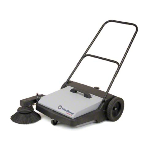
- Page 1 SelectSweep Operator and Parts Manual Manual del Operador y de Accessorios Nilfisk-Advance Model 56100874 ™ English Espanol revised 4/00 Form Number 56041492 87522-48...
-
Page 2: Specifications
Please read and save these instructions. Read carefully before attempting to assemble, install, operate or maintain the products described. Protect yourself and others by observing all safety information. Failure to comply with instructions could result in personal injury and/or property damage! Retain instructions for future reference. Model: 56100874 Commercial/Industrial Use Description... - Page 3 Assembly Figure 1 ASSEMBLING HANDLE Lower 1. Place ends of lower handle into holes of sweeper Handle frame. Attach with screws (see Figure 1). 2. Attach upper handle to lower handle using machine screws, lockwashers, and nuts (see Sweeper Figure 2). Frame 3.
-
Page 4: Maintenance
EMPTYING DIRT HOPPER 1. To empty the dirt hopper, lift up on the handle located on the front of the hopper, and empty contents into a proper container. 2. Replace dirt hopper back on sweeper by placing front edge of hopper on sweeper frame. 3. - Page 5 STANDARD ACCESSORIES Wide 19" (48.26 cm) Main broom 13" Diameter (33.02 cm) Side broom 8 Gallon (30.28 liters) Large capacity hopper 27 26 ITEM DESCRIPTION Upper Handle - 20 x 1 ” Slotted truss head screw Lower handle ” - 20 Hex nut ”, External tool lockwasher ”...
- Page 6 Adjusting Side Broom Arm ITEM DESCRIPTION PART NO. Hairpin Clevis pin ” - 20 hex nut Stop adjustment knob -16 x 4” Round head bolt, (square neck) ” Threaded insert Stop adjustment foot Side broom arm ” Flat washer Side broom shaft O-ring Bearing Side broom cover...
-
Page 7: Especificaciones
Lea y guarde estas instrucciones. Lea detenidamente antes de intentar ensamblar, instalar, operar o realizar el mantenimiento de los productos. Protéjase a usted mismo y a los demás, observando toda la información sobre seguridad. Cualquier error en el cumplimiento de las instrucciones puede provocar lesiones personales y/o daños de propiedad. Conserve las instrucciones para futuras referencias. - Page 8 Figura 1 Manubrio Inferior Manubrio Superior Manubrio Inferior Figura 2 ENSAMBLAJE DE LA ESCOBILLA Agarradera de la Tolva LATERAL Refiérase a la Figura 4 1. La banda de transmisión deberá colocarse en la polea cuando hya sido recibida. Verifique que la banda esté vien colocada en la polea y entre las guías.
-
Page 9: Mantenimiento
Figura 7 - Procedimiento de Vaciado Tolva Vacía Armazón de la Bareredora 4. La Tolva deberá vaciarse después de cada uso, o conforme se requiera. Una tolva saturada podría afectar la eficiencia en el funcionamiento de su barredora. Mantenimiento 1. Después de cada uso, revise las cerdas y las ruedas por los posibles materiales que hayan quedado atrapados en éstas, y quítelos inmediatamente. - Page 10 Notes...
- Page 11 Nilfisk-Advance, Inc. 14600 21st Avenue North Plymouth, MN, 55447-3408 www.nilfisk-advance.com Phone: 800-989-2235 Fax: 800-989-6566 ©2000 Nilfisk-Advance, Inc., Plymouth, MN 55447-3408 Printed in the U.S.A.
Need help?
Do you have a question about the SelectSweep and is the answer not in the manual?
Questions and answers