Table of Contents
Advertisement
Installation, Operation, and Maintenance
Trane® Pivot™ Smart Thermostat
BAYSTAT814*
Only qualified personnel should install and service the equipment. The installation, starting up, and servicing of heating, ventilating, and air-conditioning equipment
can be hazardous and requires specific knowledge and training. Improperly installed, adjusted or altered equipment by an unqualified person could result in death or
serious injury. When working on the equipment, observe all precautions in the literature and on the tags, stickers, and labels that are attached to the equipment.
August 2022
SAFETY WARNING
BAS-SVX078E-EN
X39641353001
Advertisement
Table of Contents

Related Manuals for Trane Pivot BAYSTAT814 Series


Summary of Contents for Trane Pivot BAYSTAT814 Series
- Page 1 Installation, Operation, and Maintenance Trane® Pivot™ Smart Thermostat BAYSTAT814* X39641353001 SAFETY WARNING Only qualified personnel should install and service the equipment. The installation, starting up, and servicing of heating, ventilating, and air-conditioning equipment can be hazardous and requires specific knowledge and training. Improperly installed, adjusted or altered equipment by an unqualified person could result in death or serious injury.
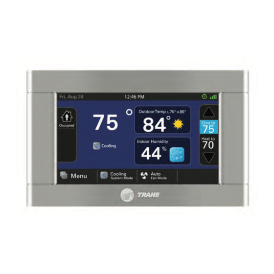
- Page 2 Introduction The Trane® Pivot™ Smart Thermostat is a programmable thermostat that features a color touch-screen and an intuitive user interface for easy operation. With built-in remote access capability, users can easily perform tasks via a mobile device (iOS or Android).
- Page 3 Non-Trane personnel should always follow local regulations. Copyright This document and the information in it are the property of Trane, and may not be used or reproduced in whole or in part without written permission. Trane reserves the right to revise this publication at any time, and to make changes to its content without obligation to notify any person of such revision or change.
-
Page 4: Table Of Contents
Table of Contents Specifications ..............6 Contents and Accessories. - Page 5 Table of Contents Humidifier Operation ............35 Optimal Start/Stop .
-
Page 6: Specifications
Specifications Specification Description Specification Description 4.15 inches x 2.65 inches Touch Screen Display Auxiliary Heat Lockout 32°F to 70°F (4.3 inches diagonal) • Heat/cool • Dual fuel Configurations Compressor Heat Lockout 5°F to 70°F • Heat only • Cooling only •... -
Page 7: Contents And Accessories
Contents and Accessories • One (1) Thermostat BAYSTAT814A • One (1) Sub-base • Three (3) #6, 18x1 Phillips Slotted Head Mounting Screws • Three (3) #6x1 Nylon Drywall Anchors • One (1) Installation, Operation, and Maintenance Guide • One (1) RJ-45 Holder and Screw •... -
Page 8: Installation And Wiring
Installation and Wiring Location The Pivot thermostat is designed for installation in climate controlled spaces. Use the following guidelines during installation: • Place the unit in a central location with good air circulation. • For proper temperature sensing, avoid exposing the unit to heat radiating from lamps, sunlight, fireplaces, or any other radiant heat sources. -
Page 9: Mounting
Installation and Wiring – Choose a mounting location that ensures adequate signal strength from the unit to the Internet router. – Do not mount the unit more than 30 feet from the wireless router. – For strong signal strength, ensure there are no more than three (3) interior walls between the unit and the router. - Page 10 Installation and Wiring 6. Drill the holes. Note: An optional mounting hole is provided for more secure mounting. Note: If using a wireless Internet connection, proceed to Step 7. When using a wired Ethernet connection: a. With the sub-base and RJ-45 properly oriented, press the holder into the sub-base as shown below.
-
Page 11: Wiring
Installation and Wiring Note: Ensure all wires extend through the hole in the sub-base as shown below. Wiring 1. Adjust the length and position of each wire so they reach the proper terminal on the connector block of the sub-base. 2. -
Page 12: Wiring Diagrams
Installation and Wiring Wiring Diagrams Figure 1. Trane Reliatel 1 or 2 stage constant volume rooftop unit with non-variable speed blower Important: Do not run Outdoor/Remote sensor wires in the same bundle with HVAC wires. Keep away from high voltage wiring to avoid interference. - Page 13 Installation and Wiring Figure 2. Trane Reliatel 1 or 2 stage heat pump rooftop unit with non-variable speed blower Important: Do not run Outdoor/Remote sensor wires in the same bundle with HVAC wires. Keep away from high voltage wiring to avoid interference.
- Page 14 Installation and Wiring Figure 3. Generic constant volume rooftop unit with non-variable speed blower Important: Do not run Outdoor/Remote sensor wires in the same bundle with HVAC wires. Keep away from high voltage wiring to avoid interference. BAS-SVX078E-EN...
- Page 15 Installation and Wiring Figure 4. Package 1 or 2 stage generic heat pump rooftop unit with non-variable speed blower Important: Do not run Outdoor/Remote sensor wires in the same bundle with HVAC wires. Keep away from high voltage wiring to avoid interference. BAS-SVX078E-EN...
- Page 16 Installation and Wiring Figure 5. Reliatel constant volume with non-variable speed blower and occupancy signal for economizer Aux 1 must be set up as a Ventilation output with minimum run time 60 minutes per hour. Done this way, AUX 1 output acts as an Occupancy signal.
- Page 17 Installation and Wiring Figure 6. Trane Reliatel 1 or 2 stage constant volume rooftop unit with non-variable speed blower and dehumidification AUX 1 (or AUX 2) must be set up for Dehumidi cation and the on-board humidity sensor must be enabled in Installer Setup.
-
Page 18: System Setup
System Setup Power-up Sequence The unit initiates a 90 to 120 second power-up sequence. During the sequence, the Screen Calibration option is made available for five (5) seconds. However, Screen Calibration is available for five (5) minutes if the screen has never been calibrated and following a Restore Factory Defaults command. Note: The Pivot thermostat comes factory calibrated. -
Page 19: Settings
[with Cooling Call], with Heating Call Select which mode of operation energizes the SOV Operation switch-over valve. Variable speed applies only to supported Trane residential equipment Table 2. Group 2 equipment settings Menu Item Options [Default] Description... - Page 20 System Setup Table 3. Group 3 sensor settings Menu Item Options [Default] Description [No]*, [Yes] This menu item is asking if the installer wants to use Internet Weather as a temperature source for lockouts during heat pump operation, temperature overrides for outdoor air temperature ventilation, or outdoor temperature for Optimal Start/Stop calculations.
- Page 21 System Setup Table 3. Group 3 sensor settings (continued) Menu Item Options [Default] Description [Input ODT], Installer entered name Pressing the Input ODT button brings up a keypad allowing the installer to name the button, such as “Occupancy”. The input value will be available on a widget that can be displayed on the Home screen by navigating to Home >...
- Page 22 System Setup Table 3. Group 3 sensor settings (continued) Menu Item Options [Default] Description [Closed], Installer entered name Installer can rename the Closed state using up to 20 characters, for example, “Unoccupied.” RS1 Binary Input Closed State Label Note: Special characters exist that cannot be used in the name.
- Page 23 System Setup Table 4. Group 4 accessories settings Menu Item Options [Default] Description Air Cleaner, Select the filter type installed Filtration Type Installed [Media Filter] [None], Yes Select whether a humidifier is installed Humidifier Installed [Aux1], Aux2 Select which set of Aux contacts is controlling the Humidifier —...
- Page 24 Variable speed applies only to supported Trane residential equipment For a Trane ReliaTel controls with Economizer configure minimum runtime for ventilation at 60 minutes per hour, blower with interlock, and ventilate on open for relay configuration. This configuration will tell the economizer when occupied provide minimum ventilation.
- Page 25 Compressor 1st stage Air Flow% — Comp Htg compressor unit in heating mode. Variable speed applies only to supported Trane residential equipment Table 7. Group 7 lockout (Must have OAT enabled to use either Internet Weather or a sensor wired to ODT input for...
-
Page 26: Service Reminders
Contractor Diagnostic Portal. If contractors do not have an account in ComfortSite, they will need to work with their local Trane office to set up the account. The contractor information required in the thermostat can be left blank until a contractor account has been set up in ComfortSite. At the thermostat navigate to Home >... -
Page 27: Pivot Mobile App Setup
It may be necessary or expected for the installer to help customers set up their mobile device and connect to the Pivot thermostat. Refer to the Trane Pivot Smart Thermostat User Guide (BAS-SVU044) for information on creating an account and adding users and thermostats to the account. -
Page 28: Operation
Operation PI Control The Pivot thermostat uses proprietary control schemes to provide comfort and energy efficiency. The unit senses the indoor temperature and determines capacity required based on the following: • Mode of Operation • Proportional Error- Distance from Setpoint •... -
Page 29: Duty Cycles
Operation Duty Cycles Indoor temperature control is achieved by duty-cycling the equipment when the load value is less than 100% of the current stage of operation. The duty cycle rate is dependent on the calculated load value. The illustration below shows the number of cycles at 50% load, for example, LV = 50. With all PI-based controls, the indoor temperature fluctuates above/below the user-selected setpoint to maintain comfort in the space. -
Page 30: Staging Inhibits
Operation Staging Inhibits When the stage threshold is exceeded, a stage inhibit is applied. The stage inhibit calculates the rate of recovery over a 10 minute period and determines if the next stage is required to meet the current demand. If the rate of recovery is great enough, a new 10 minute inhibit is enabled. The unit will not go to the next stage of operation until it determines that the current stage cannot satisfy the current demand. -
Page 31: Modes
Operation Modes System Mode The Pivot thermostat has five (5) system modes: • Heating; system only operates in heating mode. • Cooling; system only operates in cooling mode. • Off; system does not operate in either heating/cooling modes. • Emergency Heating; system operates only the indoor heat source. Note: Only available when the outdoor unit type is a heat pump. -
Page 32: Fan Mode
Operation Fan Mode The Pivot thermostat has two (2) fan modes: • Auto; fan runs only with a call for heating or cooling. • On; fan runs continuously while in occupied mode. In unoccupied mode the fan will only run when there is a call for heating or cooling. -
Page 33: Advanced Operation
This option is enabled by navigating to Installer Settings > Comfort Settings > Smart Continuous Fan. • Airflow reduction (applies only to Trane residential variable speed blowers) – If BK is connected, the unit can reduce the system airflow by 30% anytime the indoor RH is higher than the cooling RH target. -
Page 34: Dual Fuel Operations (Heat Pump With Aux Indoor Heat)
Advanced Operation • Active call for cooling only – Dehumidifier can operate only during an active call for cooling. Dehumidifier control options are accessed by navigating to Installer Setup > Accessories Settings. Note: Pivot thermostat has an onboard humidity sensor which can be enabled through Installer Setup >... -
Page 35: Lockouts
Advanced Operation Note: An outdoor temperature sensor must be enabled for lockout settings to be available. Lockout options are set by navigating to Installer Setup > Lockout Settings. Lockouts The Pivot thermostat lockout methods are: • Auxiliary heat lockout – When enabled, select an outdoor temperature which disables auxiliary heat anytime the outdoor temperature is above the selected temperature. -
Page 36: Optimal Start/Stop
Advanced Operation • RH control – Dry contacts are closed anytime the indoor humidity is less than the heating target relative humidity. • Frost control – The unit references the outdoor temperature through a wired outdoor air temperature sensor and structure integrity to offset the heating target relative humidity. This helps to limit the risk of frost or condensation from forming on interior walls and windows. -
Page 37: Recovery
Advanced Operation only occur on peak energy demand days. The Pivot thermostat now has OADR screens which allows it to participate in these events if the user chooses. To register your thermostat in the Demand Response program, navigate to Home > Menu > System Info >... -
Page 38: Warm Air Discharge
Aux output will be on during occupied periods, and off during unoccupied periods, and therefore will act as an occupancy output signal, Refer to figure 5 in the Wiring section for an example of a typical Trane installation. Warm Air Discharge Enabling warm air discharge with BK connected reduces the variable speed blower airflow by 20% when in compressor heating operation. -
Page 39: Diagnostics
Diagnostics All screens in the Diagnostics section can be accessed by navigating to Home > Menu > Service > Technician Access (press for 5 seconds) >Proceed > Service Menu. Note: A PIN access code may have been previously set up on the thermostat by the building owner, which may restrict access to the Menu screen and/or Service screen. -
Page 40: History
Diagnostics • Alert history; cleared alerts of the last 30 days. From both screens, an alert code can be selected and get additional information on the alert as well as a list of possible causes. Note: Each alert has a date/time stamp of when the alert was nullified. The date/time stamp for current alerts occurs when the alert was declared. -
Page 41: Restore Factory Defaults
Diagnostics • Indoor Temperature • Indoor Relative Humidity • Heating/Cooling Setpoints • Relative Humidity Setpoints • Dehumidifier Status • Outdoor Temperature Current energized terminals display in green at the bottom of the system report screen. Restore Factory Defaults Restoring factory defaults writes over all saved settings. Restore Defaults is accessed by navigating to Service Menu >... -
Page 42: Troubleshooting
Troubleshooting Symptom Possible causes Action Pivot thermostat displays an alert code on the A critical or major alert is present Navigate to the Diagnostic screen on the Pivot screen. thermostat for a Problem Description and Possible Cause. Display will not come on Loss of 24 Vac between R &... -
Page 43: Pin Access Code
Troubleshooting Symptom Possible causes Action Heat pump is not turning on; only furnace or electric Outdoor temperature is below compressor Adjust the compressor lockout temperature heat strips are running. lockout temperature setting. setting if desired. System mode is set to Emergency Heat. Check/repair outdoor temperature sensor or wiring. -
Page 44: Pivot Smart Thermostat Support
Troubleshooting Pivot Smart Thermostat Support For issues with thermostat setup and operation, or with the Trane Pivot mobile app, contact Pivot Support (833)-222–3201. BAS-SVX078E-EN... -
Page 45: Fcc And Ic Notices
FCC and IC Notices 10.1 FCC Notice FCC ID: XVR-CONT8245 INFORMATION TO USER This device complies with Part 15 of the FCC Rules. Operation is subject to the following two conditions: (1) This device may not cause harmful interference and (2) This device must accept any interference that may cause undesired operation. - Page 46 Notes BAS-SVX078E-EN...
- Page 47 Notes BAS-SVX078E-EN...
- Page 48 For more information, please visit trane. com or tranetechnologies.com. Trane has a policy of continuous product and product data improvements and reserves the right to change design and specifications without notice. We are committed to using environmentally conscious print practices.
Need help?
Do you have a question about the Pivot BAYSTAT814 Series and is the answer not in the manual?
Questions and answers
How to hard reset my trane thermostat