Proxim Tsunami MP.11 Installation And Management Manual
Hide thumbs
Also See for Tsunami MP.11:
- Installation and management manual (158 pages) ,
- Installation manual (80 pages) ,
- Specification (58 pages)

Related Manuals for Proxim Tsunami MP.11


Summary of Contents for Proxim Tsunami MP.11
- Page 1 Part Number 68568r1 Tsunami MP.11 and MP.11a Version 2.1 Installation and Management Outdoor: BSU Indoor Outdoor: SU...
-
Page 2: Copyright
COPYRIGHT ©2004 Proxim Corporation, Sunnyvale, CA. All rights reserved. Covered by one or more of the following U.S. patents: 5,231,634; 5,875,179; 6,006,090; 5,809,060; 6,075,812; 5,077,753. This manual and the software described herein are copyrighted with all rights reserved. No part of this publication may be reproduced, transmitted, transcribed, stored in a retrieval system, or translated into any language in any form by any means without the written permission of Proxim Corporation. -
Page 3: Table Of Contents
MP.11 and MP.11a Installation and Management Contents Copyright ................................2 Trademarks ................................2 FCC COMPLIANCE .............................2 CHAPTER 1. OVERVIEW ............................5 In This Release ..............................6 Wireless Network Topologies..........................6 Active Ethernet ..............................7 Identifying Network Topology and Equipment .....................8 Finding a Suitable Location..........................8 CHAPTER 2. INSTALLATION ..........................9 Installing the Indoor MP.11/a ..........................9 Installing the Outdoor MP.11/a...........................16 Installing Documentation and Software ......................21... - Page 4 MP.11 and MP.11/a Quick Install Guide Radio Specifications............................130 APPENDIX B. TROUBLESHOOTING ........................132 MP.11/a Connectivity Issues..........................132 Setup and Configuration Issues ........................134 APPENDIX C. SUPPORT AND CONTACTS .......................136 GLOSSARY................................137 Contents...
-
Page 5: Chapter 1. Overview
MP.11 and MP.11a Installation and Management Chapter 1. Overview The Tsunami MP.11 and MP.11a are flexible wireless outdoor routers that let you design solutions for point-to- point links and point-to-multipoint networks. The Tsunami MP.11 and MP.11a are product families comprising several products (such as the MP.11 2411 Base Station and the MP.11 2411 Residential Subscriber Unit). -
Page 6: In This Release
MP.11 and MP.11/a Quick Install Guide IN THIS RELEASE • Ruggedized, outdoor version of Tsunami MP.11/a • Antenna alignment tool with audio support • Reporting and logging of internal unit temperature • Transmit Power Control support enhanced: Tsunami MP.11 Version 2.0 Tsunami MP.11 Version 2.1... -
Page 7: Active Ethernet
MP.11 and MP.11/a Quick Install Guide Point-to-Multipoint Network If you want to connect more than two buildings, you can set up a single point-to-multipoint network with a single Base station and multiple Subscriber Units, as depicted in the following figure. Up to 250 Subscriber Units (SUs) can be connected to a Base Station. -
Page 8: Identifying Network Topology And Equipment
To make optimal use of the MP.11/a, you must find a suitable location for the hardware. The radio range of the MP.11/a largely depends upon the position of the antenna. Proxim recommends you do a site survey, observing the following requirements, before mounting the MP.11/a hardware. -
Page 9: Chapter 2. Installation
º Four 6 mm x 35 mm plugs • One power supply • One Tsunami MP.11/a Installation CD-ROM containing: º Software Installation Package (starts automatically when CD is inserted in CD-ROM drive; can be started by double-clicking SETUP.EXE). º Online Help º... - Page 10 Wall mounting hardware Power supply with power cord The shipment also includes the Tsunami MP.11/a Quick Install Guide. 2. If you intend to install the unit free-standing, or if you intend to mount it to the ceiling, use a Phillips screwdriver to attach the metal base to the underside of the unit.
- Page 11 MP.11 and MP.11/a Quick Install Guide 4. Remove the cable cover. 5. Remove the front cover from the unit (the side with the LED indicators, shown in the figure on left); then remove the back cover (figure on right). 6. Connect the grounding wire to the MP.11/a using the Faston plug on the metal case, next to the power plug. 7.
- Page 12 MP.11 and MP.11/a Quick Install Guide 9. Connect the free end of the Ethernet cable to a hub, switch, patch panel, Active Ethernet power injector, or an Ethernet port on a computer. 10. If using AC power, connect the power cord to a power source (such as a wall outlet) to turn on the unit. 11.
- Page 13 MP.11 and MP.11/a Quick Install Guide 4. Press down on the cable cover lock to release the cable cover . 5. Remove the cable cover from the unit. 6. Remove the front and back covers from the unit. 7. Place the back cover on the mounting location and mark the center of the three mounting holes. 8.
- Page 14 MP.11 and MP.11/a Quick Install Guide Ceiling Mounting Follow these steps to mount the MP.11/a to a ceiling: 1. If the MP.11/a’s power supply is plugged in, unplug it. 2. Use a Phillips screwdriver to attach the metal base to the underside of the MP.11/a, if you have not already done so.
- Page 15 MP.11 and MP.11/a Quick Install Guide Power Power is not present or is malfunctioning. GREEN Power is present; the unit is operational. AMBER The unit is initializing after reboot (less than two minutes); it cannot get a dynamic IP address or is in Forced Reload state when Ethernet LED also is amber.* A fatal error in the unit.
-
Page 16: Installing The Outdoor Mp.11/A
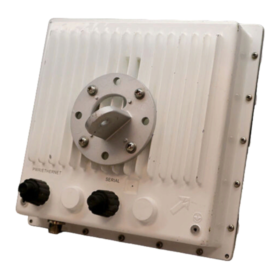
You also can mount the radios on tall, multi-section poles with guide wires. For these types of installations, you should consult professionals with experience. The Outdoor MP.11/a Product Package Each outdoor MP.11/a comes with the following, as well as a printed copy of the Tsunami MP.11/a Quick Install Guide. 1. One MP.11/a Ruggedized... - Page 17 Keep this information in a safe place. The MAC address is required to add the Subscriber Unit to a Base Station database; the serial number is required to obtain support from Proxim. The outdoor MP.11/a is designed to directly mount to a pole. Using the supplied brackets and hardware, you can mount the radio to a 1-1/4 inch to 3-inch pole (outside diameter).
- Page 18 MP.11 and MP.11/a Quick Install Guide For horizontal alignment, mount the radio as shown below: 4. Attach bracket connector (C) to mounting piece (A) with the screw provided, as shown below. This extension piece gives the radio more possible tilt, letting you more accurately adjust for elevation. 5.
- Page 19 MP.11 and MP.11/a Quick Install Guide To wall-mount the outdoor MP.11/a, mount bracket (E) to wall using 4 screws provided, as shown: Switching On the Outdoor MP.11/a You can power on the outdoor MP.11/a by connecting the Active Ethernet splitter to the Ethernet cabling. When the power is switched on, the MP.11/a performs startup diagnostics.
- Page 20 The integrated antenna is supported on Subscriber Units only; the Base Station has an external antenna connector and no integrated antenna. For more information about external antennas, see the Tsunami MP.11 Antenna Installation Guide and Tsunami MP.11a Antenna Installation Guide.
-
Page 21: Installing Documentation And Software
This is the help for the Web Interface. It is stored on your computer or network so it is always available. Documentation Documentation also is available in an electronic (PDF) form, including the Tsunami MP.11/a Installation and Management Guide, Tsunami MP.11/a Antenna Installation Guide, and Tsunami MP.11/a Quick Install Guide. - Page 22 MP.11 and MP.11/a Quick Install Guide When the antenna is aimed, the beep can easily be heard if the SNR is rising (shorter period, higher frequency) or falling (longer period). When the position of the antenna has been changed, the SNR averaging settles at the new value and the beeping returns to the average length so the antenna can again be aimed towards rising SNR.
-
Page 23: Chapter 3. Management Overview
MP.11 and MP.11a Installation and Management Chapter 3. Management Overview This chapter describes how to gain access to the MP.11/a for configuration and management. Three interfaces are provided for viewing or changing the MP.11/a’s settings: Web Interface The Web Interface is a graphical interface based upon Web pages from a built-in Web server. Command Line Interface The Command Line Interface (CLI) is a text-based interface using typed commands. - Page 24 MP.11 and MP.11/a Quick Install Guide Setting the IP Address If you want to set the IP address: 1. Run ScanTool on a computer connected to the same LAN subnet as the MP.11/a, or directly connected to the MP.11/a with a cross-over Ethernet cable. ScanTool scans the subnet for MP.11/a units and displays the units it finds in the main window.
-
Page 25: Web Interface Overview
MP.11 and MP.11/a Quick Install Guide Note: The asterisks displayed when you enter the password are a set number that does not necessarily equal the number of characters in the actual password string. This is intended for added security. WEB INTERFACE OVERVIEW The Web Interface provides a graphical user interface through which you can easily configure and manage the MP.11/a. - Page 26 MP.11 and MP.11/a Quick Install Guide You now have access to the MP.11/a Web Interface. To view or change basic system information, click the Configure button on the left side of the Web interface window, then click the System tab. Chapter 3.
-
Page 27: Mp.11A Country Options
MP.11a COUNTRY OPTIONS Selecting a Country The Tsunami MP.11/a Configure System window provides a selectable Country field that automatically provides the allowed bandwidth and frequencies for the selected country as well as, where applicable, Dynamic Frequency Selection (DFS) and Transmit Power Control (TPC). - Page 28 MP.11 and MP.11/a Quick Install Guide The event log shows the selected power for all data rates, so you must look up the relevant data rate to determine the actual power level. For example, the event log shows: 0 00:00:08–INFO- Final Power 6 Mb 20 dBm, MaxRD 30 dBm, MaxEdge 31 dBm, -TPC Scale 0 dBm – Ant Red 0 dBm* 0 00:00:09–INFO- 20 dBm | 20 dBm | 20 dBm | 20 dBm | 20dBm | 19 dBm This shows that the output power is set at 20 dBm for the data rate 6, 9, 12, 18, or 24 Mbps or at 19 dBm when the selected data rate is 36 Mbps.
-
Page 29: Command Line Interface Overview
MP.11 and MP.11/a Quick Install Guide COMMAND LINE INTERFACE OVERVIEW The Command Line Interface (CLI) is a text-based interface with which you can configure and manage the MP.11/a by entering commands. This section describes only how to access the CLI; the interface itself is described in “Chapter 6. - Page 30 • An ASCII terminal program, such as HyperTerminal. Proxim recommends you switch off the MP.11/a and the computer before connecting or disconnecting the serial cable. Note: For the outdoor MP.11/a, you can connect to the serial port by connecting the included RJ-11 to DB-9 connector from the radio (RJ-11 connection) to your computer’s serial port (DB-9 connection).
- Page 31 MP.11 and MP.11/a Quick Install Guide HyperTerminal Connection Properties The serial connection properties can be found in HyperTerminal as follows: 1. Start HyperTerminal and select Properties from the File menu. 2. In the Connect using: drop-down list, select Direct to Com1 (depending upon the COM port you use) and click Configure…;...
-
Page 32: Chapter 4. Basic Management
MP.11 and MP.11a Installation and Management Chapter 4. Basic Management This chapter describes the initial setup of the MP.11/a, which lets you configure and monitor the basic features of the MP.11/a. In most cases, configuring these basic features is sufficient. A full overview of the Web Interface is provided in “Chapter 5. -
Page 33: Rebooting And Resetting
Save command, a power outage would wipe out all changes since the last reboot. For example, entering static routes takes effect immediately; however, the routes are not saved until the unit has gone through a controlled reboot. Proxim strongly recommends saving your settings immediately when you finish making changes. -
Page 34: General Settings
MP.11 and MP.11/a Quick Install Guide Soft Reset to Factory Default If necessary, you can reset the MP.11/a to the factory default settings. This must be done only when you are experiencing problems. Resetting to the default settings requires you to again configure the MP.11/a. To reset to factory default settings: 1. - Page 35 MP.11 and MP.11/a Quick Install Guide System Configuration The System Configuration page lets you change the MP.11/a’s system name, location name, and so on (see the following System Configuration window). These details help distinguish this MP.11/a from other routers, and let you know whom to contact in case of problems.
- Page 36 MP.11 and MP.11/a Quick Install Guide IP Configuration The IP Configuration window lets you change the MP.11/a IP parameters. These settings differ when the MP.11/a is in Routing mode. To go to this page, click the Configure button, the Network tab, then the IP Configuration sub-tab. See “IP Configuration”...
- Page 37 MP.11 and MP.11/a Quick Install Guide Interface Configuration The Interfaces configuration pages let you change the MP.11/a Ethernet and wireless parameters. The Wireless tab is displayed by default when you click the Interfaces tab. Wireless To configure the wireless interface, click the Configure button followed by the Interfaces tab; then click the Wireless sub-tab.
- Page 38 MP.11 and MP.11/a Quick Install Guide Ethernet Port To configure the Ethernet interface, click the Configure button, the Interfaces tab, and the Ethernet sub-tab. You can set the Configuration parameter from this tab. Select from the following settings for the type of Ethernet transmission.
-
Page 39: Monitoring Settings
MP.11 and MP.11/a Quick Install Guide MONITORING SETTINGS The MP.11/a offers various facilities to monitor its operation and interfaces. Only the most significant monitoring categories are mentioned here. Wireless To monitor the wireless interfaces, click the Monitor button and the Wireless tab. This tab lets you monitor the general performance of the radio and the performance of the WORP Base or WORP subscriber interfaces. - Page 40 MP.11 and MP.11/a Quick Install Guide Interfaces To monitor transmission details, click the Monitor button and the Interfaces tab. The Interfaces tab provides detailed information about the MAC-layer performance of the MP.11/a interface. Chapter 5. Web Interface...
-
Page 41: Security Settings
MP.11 and MP.11/a Quick Install Guide SECURITY SETTINGS To prevent misuse, the MP.11/a provides wireless data encryption and password-protected access. Be sure to set the encryption parameters and change the default passwords. Encryption You can protect the wireless data link by using encryption. Encryption keys can be 5 (64-bit), 13 (WEP 128-bit), or 16 (AES 128-bit) characters in length. -
Page 42: Upgrading The Mp.11/A
Updating the embedded software is described in “Image File Download” on page 123. A TFTP server is provided on the Tsunami MP.11/a Documentation and Software CD-ROM; the server is required to transfer the downloaded file to the MP.11/a. Notes: •... -
Page 43: Chapter 5. Web Interface
MP.11 and MP.11a Installation and Management Chapter 5. Web Interface This section covers the Web Interface of the MP.11/a. The interface is described hierarchically according to these buttons, which appear on the left side of the Web page: • Status below •... - Page 44 Click the Status button and the Event Log tab to view the contents of your Event Log. The Event Log keeps track of events that occur during the operation of the Tsunami MP.11/a. The Event Log displays messages that may not be captured by System Traps, such as the Transmit Power for the Frequency Channel selected.
-
Page 45: Configure
MP.11 and MP.11/a Quick Install Guide CONFIGURE Use the Configure section to change the settings of the MP.11/a. There are 10 tabs in this section. Note: The Intra-Cell Blocking tab is available for Base Stations in Bridge mode only. The NAT tab is available for SUs in Routing mode only. - Page 46 MP.11 and MP.11/a Quick Install Guide You can enter the following details: System Name This is the system name for easy identification of the MP.11/a Base Station or SU. Use the system name of a Base Station to configure the Base Station System Name parameter on an SU if you want the SU to register only with this Base Station.
- Page 47 MP.11 and MP.11/a Quick Install Guide 2) Network IP Configuration The IP Configuration window lets you change the MP.11/a IP parameters. These settings differ when the MP.11/a is in Routing mode. Click the Configure button, the Network tab, and the IP Configuration sub-tab to view and configure local IP address information.
- Page 48 MP.11 and MP.11/a Quick Install Guide Spanning Tree The Spanning Tree Protocol (STP) can be used to create redundant networks (“hot standby”) and to prevent loops. If enabled, Spanning Tree prevents loops by disabling redundant links; if a link fails, it can automatically enable a backup link.
- Page 49 MP.11 and MP.11/a Quick Install Guide IP Routes (Routing Mode only) Click the Configure button, the Network tab and the IP Routes sub-tab to configure IP routes. You cannot configure IP Routes in Bridge mode. In Routing mode, the Add Table Entries and Edit/Delete Table Entries buttons are enabled.
- Page 50 Base Station. Roaming provides MAC level connectivity to the SU that roams from one Base Station to another. Proxim does not guarantee that upper layer protocol sessions will survive. Click the Configure button, the Network tab and the Roaming sub-tab to configure Roaming.
- Page 51 MP.11 and MP.11/a Quick Install Guide The Roaming feature lets the SU monitor local SNR and data rate for all frames received from the current Base Station. As long as the average local SNR for the current Base Station is greater than the slow scanning threshold, and the number of retransmitted frames is greater than the slow scanning threshold given in percentage, the SU does not scan other channels for a better Base Station.
- Page 52 MP.11 and MP.11/a Quick Install Guide DHCP Server Click the Configure button, the Network tab, and the DHCP Server sub-tab to enable the MP.11/a DHCP Server. When enabled, the DHCP server allows allocation of IP addresses to hosts on the Ethernet side of the SU or BSU.
- Page 53 MP.11 and MP.11/a Quick Install Guide Gateway IP Address The MP11/a supplies this gateway IP address in the DHCP response. Indicates the IP address of a router assigned as the default gateway for hosts on the Ethernet side. Primary DNS IP Address The MP11/a supplies this primary DNS IP address in the DHCP response.
- Page 54 MP.11 and MP.11/a Quick Install Guide DHCP Relay Agent (Routing mode only) Click the Configure button, the Network tab, and the DHCP RA sub-tab to enable the MP.11/a DHCP Relay Agent. When enabled, the DHCP relay agent forwards DHCP requests to the set DHCP server. Note that DHCP Relay Agent parameters are configurable only in Routing mode.
- Page 55 MP.11 and MP.11/a Quick Install Guide 3) Interfaces Wireless To configure the wireless interface, click the Configure button followed by the Interfaces tab; then click the Wireless sub-tab. For Base Station units, the wireless interface can be placed in either WORP Base or WORP Satellite mode (selected from the Interface Type drop-down box).
- Page 56 Further security is provided by mutual authentication of the Base Station and Subscriber Unit using the Network Secret. Dynamic Data Rate Selection (DDRS) Status (Tsunami MP.11/a only) The WORP Dynamic Data Rate Selection (DDRS) lets the Base Station and SUs monitor the remote average signal-to-noise ratio (SNR) and to adjust the data rate to an optimal value (to provide best possible throughput) according to the current communication conditions during run-time.
- Page 57 MP.11 and MP.11/a Quick Install Guide Transmit Power Control By default, the Tsunami MP.11a lets you transmit at the maximum output power for the country or regulatory domain and frequency selected. However, with Transmit Power Control (TPC), you can adjust the output power of the unit to a lower level in order to reduce interference from neighboring devices or to use a higher gain antenna without violating the maximum radiated output power allowed for your country.
- Page 58 MP.11 and MP.11/a Quick Install Guide The channels and frequencies scanned when DFS is enabled are listed in the following table. Frequency Channels 36 Mbps 6-24 Mbps 5.47 – 5.70 GHz 100, 104, 108, 112, 116, 17.4 17.4 120, 124, 128, 132, 136, 5.25 –...
- Page 59 MP.11 and MP.11/a Quick Install Guide Input / Output Bandwidth Limit These parameters limit the data traffic received on the wireless interface and transmitted to the wireless interface, respectively. Selections are in steps of 64 Kbps from 64 to 108,032 kbps. Ethernet You can set the desired speed and transmission mode from this tab.
- Page 60 MP.11 and MP.11/a Quick Install Guide 4) SNMP Click the Configure button and the SNMP tab to enable or disable trap groups, and to configure the SNMP management stations to which the MP11/a sends system traps. Trap Groups You can enable or disable different types of traps in the system. By default, all traps are enabled. Trap Host Table This table shows the SNMP management stations to which the MP.11/a sends system traps.
- Page 61 Routing Internet Protocol (RIP) is a dynamic routing protocol you can use to help automatically propagate routing table information between routers. The Tsunami MP.11/a can be configured as RIPv1, RIPv2, RIPv1 Compatible, or a combination of all three versions, while operating in Routing mode. In general, the Tsunami MP.11/a RIP module is based upon RFC 1389.
- Page 62 MP.11 and MP.11/a Quick Install Guide The following table describes the properties and features of each version of RIP supported in the Tsunami MP.11/a. Properties and Features of Supported RIP Versions RIPv1 RIPv2 RIPv1 Compatible Broadcast Multicast Broadcast No Authentication Authentication Authentication Class routing...
- Page 63 MP.11 and MP.11/a Quick Install Guide RIP Notes • Ensure that routers on the same physical network are configured to use the same version of RIP. • Routing updates occur every 30 seconds. It may take up to 3 minutes for a route that has gone down to timeout in a routing table.
- Page 64 MP.11 and MP.11/a Quick Install Guide 6) Management When you click the Management button, Passwords is displayed automatically. The other tab under Management is the Services tab. Passwords The Password tab lets you configure the SNMP, Telnet, and HTTP (Web Interface) passwords. SNMP Read Community Password The password for read access to the MP.11/a using SNMP.
- Page 65 MP.11 and MP.11/a Quick Install Guide Services The Services tab lets you configure the SNMP, Telnet, and HTTP (Web Interface) parameters. Changes to these parameters require a reboot to take effect. SNMP Configuration Settings SNMP Interface Bitmask: Configure the interface or interfaces (Ethernet, Wireless, All Interfaces) from which you will manage the MP.11/a using SNMP.
Need help?
Do you have a question about the Tsunami MP.11 and is the answer not in the manual?
Questions and answers