Advertisement
Quick Links
Advertisement

Related Manuals for NetComm InModem 56


Summary of Contents for NetComm InModem 56
-
Page 2: Table Of Contents
Table of Contents. System Requirements ......................2 Package inclusions......................... 2 Modem Installation ......................... 2 Using Your Modem......................... 4 Troubleshooting........................5 Appendix A: AT Command Reference ................... 6 Appendix B: S-Registers ...................... 21 Appendix C: Modem Specifications ..................27... -
Page 3: System Requirements
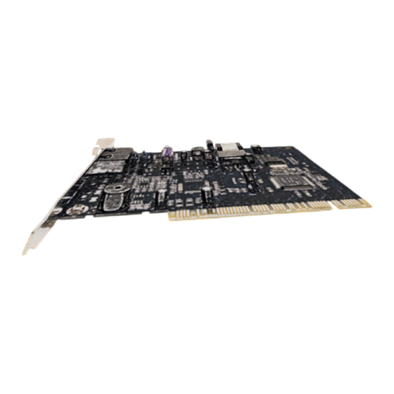
• Telephone lead (RJ11-RJ11). • Telephone lead adaptor (605 – RJ11). • Quick Start Guide. • NetComm CD. • Warranty card. • ISP (Internet Service Provider) CD. Modem Installation Turn off your computer and disconnect the power cable. Remove the cover from your computer. Please check your computer’s manual for instructions and cautions regarding the removal of covers or installation of add-in boards. - Page 4 Insert the InModem 56 into the PCI slot and secure with a screw in the backplane. Replace the Computers cover. Insert one end of the telephone cord into the Modem’s Line (top) Socket Connect the other end of the phone cord to a telephone phone point, via the supplied adaptor (RJ11-605) if required.
-
Page 5: Using Your Modem
Most Windows communications software will either auto detect your modem, or ask you which modem you wish to use with it. Choose the NetComm InModem 56 (IN5692). If the software asks you which COM port to use you can determine this by going to the Control Panel –... -
Page 6: Troubleshooting
4. Go to Control Panel – Modems – Diagnostics and highlight the Com port listed next to the NetComm InModem 56 and then click on “ More Info ”. If the modem is responding you will be presented with a window with the modems responses to a number of AT commands. -
Page 7: Appendix A: At Command Reference
Appendix A: AT Command Reference AT commands are issued to the modem to control the modem's operation and software configuration. AT commands can only be entered while the modem is in command mode. The format for entering AT commands is: TYPE: ATXn where X is the AT command and n is the specific value for that command. - Page 8 C1 : Normal transmit carrier switching. Result Codes : n = 1 ERROR Otherwise Dn Dial This command instructs the modem to begin the dialing sequence. The dial string (n, including modifiers and the telephone number) is entered after the ATD command. A dial string can be up to 60 characters long.
- Page 9 issued by older communication software, to assure backward compatibility. F0 : Online data character echo enabled (NOT SUPPORTED). F1 : Online character echo disabled. Result Codes : n = 1 ERROR Otherwise Hn Hook Control This command instructs the modem to go on-hook to disconnect a call, or off-hook to make the phone line busy.
- Page 10 8 Estimated Noise Level 152 152 9 Receive Signal Power Level (-dBm) 25 25 10 Transmit Signal Power Level (-dBm) 16 16 11 Round Trip Delay (msec) 4 4 Press any key to continue; ESC to quit. 12 Near Echo Level (-dBm) NA NA 13 Far Echo Level (-dBm) NA NA 14 Transmit Frame Count 3 3 15 Transmit Frame Error Count 0 0...
- Page 11 L0 : Selects low volume. L1 : Selects low volume. L2 : Selects medium volume (default). L3 : Selects high volume. Result Codes : n = 0, 1, 2, 3 ERROR Otherwise Mn Monitor Speaker Mode This command turns the speaker on or off. M0 : The speaker is off.
- Page 12 Q0 : Enables modem to send result codes to the computer (default). Q1 : Disables modem from sending result codes to the computer. Result Codes : n = 0, 1 ERROR Otherwise T Select Tone Dialing This command instructs the modem to send DTMF tones while dialing. Dialed digits are tone dialed until a P command or dial modifier is received.
- Page 13 Enabled : Displays basic result codes, along with the connect message and the modem's date rate, and an indication of the modem's error correction and data compression operation. Dial Tone Detect Disabled : The modem dials a call regardless of whether it detects a dial tone. The period of time the modem waits before dialing is specified in register S6.
- Page 14 &C1 : DCD turns on when the remote modem's carrier signal is detected, and off when the carrier signal is not detected (default). Result Codes: n = 0, 1 ERROR Otherwise &Dn DTR Control This command interprets how the modem responds to the state of the DTR signal and changes to the DTR signal.
- Page 15 &Kn Local Flow Control Selection &K0 : Disable flow control &K1 : Reserved &K2 : Reserved &K3 : Enable RTS/CTS (hardware) flow control (default) &K4 : Enable XON/XOFF flow control Result Codes : n = 0, 3, 4 ERROR Otherwise &Mn Asynchronous Communications Mode &M0 : Asynchronous mode (default).
- Page 16 &Sn Data Set Ready (DSR) Option This command selects DSR action. &S0 : DSR always ON (default). &S1 : DSR comes on when establishing a connection and goes off when the connection ends. Result Codes : n = 0, 1 ERROR Otherwise &Tn Self-Test Commands...
- Page 17 Backspace Char 8 S5 Blind Dial Pause 2 sec S6 NoAnswer Timeout 50 sec S7 “ , “ Pause Time 2 sec S8 Press any key to continue; ESC to quit. Option Selection AT Cmd No Carrier Disc 2000 msec S10 DTMF Dial Speed 95 msec S11 Escape GuardTime 1000 msec S12 Data Calling Tone Disabled S35...
- Page 18 \A3 : 256 characters (default). Result Codes : n = 0, 1, 2, 3 ERROR Otherwise \Bn Transmit Break to Remote In non-error-control mode, the modem will transmit a break signal to the remote modem with a length in multiples of 100ms according to parameter specified. The command works in conjunction with the \K command.
- Page 19 \K3 : Send break to remote modem immediately. (Same as 2.) \K4 : Send break to remote modem in sequence with data. \K5 : Send break to remote modem in sequence with data. (Same as 4.) (Default.) The third case is where there a break is received from a remote modem during a connection: \K0 : Clear data buffers and send break to the DTE.
- Page 20 \Rn Ring indicator signal off after the telephone call is answered (Compatibility command) \R0 : ring indicator signal is off after the telephone call is answered Result Codes : n = 0 ERROR Otherwise \Tn Inactivity Timer This command specifies the length of time (in minutes) that the modem will wait before disconnecting when no data is sent or received.
- Page 21 -V90=X - controls the downstream rate -V90? - Shows the current value -V90=? - Shows the range [0-21] The table below shows the possible values: “AT-V90=X” Downstream Rate V.90 disabled Auto Rate (default) 28000 kbit/s 29333 kbit/s 30666 kbit/s 32000 kbit/s 33333 kbit/s 34666 kbit/s 36000 kbit/s...
-
Page 22: Appendix B: S-Registers
Appendix B: S-Registers S-registers generally affect how the AT commands perform. Contents of the registers can be displayed or modified when the modem is in command mode. To display the value of an S-register: TYPE: ATSn? where n is the register number. PRESS: Enter To modify the value of an S-register: TYPE: ATSn = r where n is the register number, and r is the new register value. - Page 23 S5 Command Line Editing Character (user defined) This register sets the character recognized as a backspace and pertains to asynchronous only. The modem will not recognize the backspace character if it is set to a value that is greater than 32 ASCII. This character can be used to edit a command line. When the echo command is enabled, the modem echoes back to the local DTE the backspace character, an ASCII space character, and a second backspace character.
- Page 24 Range: 50—150 Default: 95 Units: .001 seconds S12 Escape Guard Time This register sets the value (in 20 ms increments) for the required pause after the escape sequence (default 1 s). Range: 0—255 Default: 50 Units: .02 seconds S14 General Bit Mapped Options Status Indicates the status of command options.
- Page 25 Note: If a number between 1 and 4 is entered for this register, it will set the value to 5, and the inactivity before standby will be 5 seconds. This is done for compatibility with previous products which allowed time-outs down to 1 s. Range: 0, 5—65 Default: 10 S28 V.34 Modulation Enable/Disable...
- Page 26 S37 = 14 21600 bit/s S37 = 15 24000 bit/s S37 = 16 26400 bit/s S37 = 17 28800 bit/s S37 = 18 31200 bit/s S37 = 19 33600 bit/s S38 K56flex Downstream Rate To force a particular K56flex downstream rate, use S-register S38. S38=0 disables K56flex, and may allow a more reliable V.34 connection.
- Page 27 does not tell its code type in V.8bis, then the client modem chooses based on its country ID. m-law regions are Japan, Taiwan, Korea, Hong Kong, North America, and Latin America. Everywhere else is A-law. YML545...
-
Page 28: Appendix C: Modem Specifications
Appendix C: Modem Specifications The NetComm InModem 56 is a “Win” modem. This means that the signal processing is done by the modem, but software on the computer controls the signal processing. Data Protocol Standards Protocol Speed range (BPS) V.90...
Need help?
Do you have a question about the InModem 56 and is the answer not in the manual?
Questions and answers