Table of Contents
Advertisement
Quick Links
CS-Series
P
D
RODUCT
ESCRIPTION
The DIMENSION CS-Series units are cost optimized power
supplies
without
compromising
performance. The CS-Series is part of the DIMENSION power
supply family, existing alongside the high featured Q-Series.
The CS10.243 includes all the essential basic functions. The
devices also offer PowerBoost: Power reserves of 20%, which
may even be used continuously at temperatures up to +45°C.
The most important features are the small size, high efficiency
and the wide temperature range.
The unit has an input for 100-120V mains only. This supports
regional applications and offers additional cost savings without
sacrificing functionality.
High immunity to transients and power surges as well as low
electromagnetic emission and a large international approval
package for a variety of applications makes this unit suitable for
nearly every situation.
O
N
RDER
UMBERS
Power Supply
CS10.243
Accessory
ZM1.WALL
ZM13.SIDE
YRM2.DIODE
YR40.241
Aug. 2022/ Rev. 2.1 DS-CS10.243-EN
All parameters are specified at 24V, 10A, 120Vac, 60Hz, 25°C ambient and after a 5 minutes run-in time unless otherwise noted.
quality,
reliability
and
24-28V Standard unit
(AC 100-120V-Version)
Wall mount bracket
Side mount bracket
Redundancy module
Redundancy module
www.pulspower.com Phone +49 89 9278 0 Germany
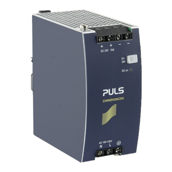
24V, 10A, 240W S
P
S
OWER
UPPLY
▪ AC 100-120V Single-Phase Input
▪ Width only 60mm
▪ Efficiency up to 91.3%
▪ Easy Fuse Breaking due to High Overload Peak Current
▪ 20% Output Power Reserves (PowerBoost)
▪ Full Output Power up to +60°C
▪ 3 Year Warranty
S
-
D
HORT
FORM
ATA
Output voltage
DC 24V
Adjustment range
24 - 28V
Output current
10.0 – 8.6A
7.5 – 6.4A
Derate linearly between +60°C and +70°C
PowerBoost
12.0A
Linear decrease to nominal power
between +45°C and +60°C
Output ripple
< 50mVpp
AC Input voltage
AC 100-120V
Mains frequency
50-60Hz
AC Input current
3.84A
DC Input voltage
-
Power factor
0.57
AC Inrush current
85A peak
Efficiency
91.3%
Losses
22.9W
Temperature range
0°C to +70°C
Hold-up time
46ms
Dimensions
60x124x117mm
Weight
700g
M
A
AIN
PPROVALS
For details and the complete approval list, see chapter 18.
UL 508
Marine
CS10.243
P
I
INGLE
HASE
up to +60°C ambient
at +70°C ambient
up to +45°C ambient
20Hz to 20MHz
±10%
±6%
at 120Vac
not allowed
at 120Vac
at 120Vac
at 120Vac
at 120Vac
operational
at 120Vac
WxHxD
UL 60950-1
Class I Div 2
Marine
NPUT
1/27
Advertisement
Table of Contents

Related Manuals for Puls DIMENSION CS Series


Summary of Contents for Puls DIMENSION CS Series
- Page 1 CS10.243 24V, 10A, 240W S CS-Series INGLE HASE NPUT OWER UPPLY ▪ AC 100-120V Single-Phase Input ▪ Width only 60mm ▪ Efficiency up to 91.3% ▪ Easy Fuse Breaking due to High Overload Peak Current ▪ 20% Output Power Reserves (PowerBoost) ▪...
-
Page 2: Table Of Contents
CS10.243 24V, 10A, 240W S CS-Series INGLE HASE NPUT NDEX Page Page Intended Use ..............3 20. Physical Dimensions and Weight ....... 20 Installation Instructions ..........3 21. Accessories..............21 AC-Input ............... 5 21.1. ZM1.WALL - Wall Mounting Bracket ....21 DC-Input ............... -
Page 3: Intended Use
CS10.243 24V, 10A, 240W S CS-Series INGLE HASE NPUT 1. I NTENDED This device is designed for installation in an enclosure and is intended for commercial use, such as in industrial control, process control, monitoring, measurement equipment or the like. Do not use this device in equipment, where malfunctioning may cause severe personal injury or threaten human life without additional appropriate safety devices, that are suited for the end-application. - Page 4 CS10.243 24V, 10A, 240W S CS-Series INGLE HASE NPUT The device is designed, tested and approved for branch circuits up to 20A without additional protection device. If an external fuse is utilized, do not use circuit breakers smaller than 16A B- or 10A C-Characteristic to avoid a nuisance tripping of the circuit breaker. The maximum surrounding air temperature is +70°C.
-
Page 5: Ac-Input
CS10.243 24V, 10A, 240W S CS-Series INGLE HASE NPUT 3. AC-I NPUT AC input nom. AC 100-120V ±10% Mains network systems TN, TT or IT AC input range 90-132Vac 85-90Vac short-term or with reduced output current 132-150Vac max. 500ms Allowed voltage L or N to earth max. - Page 6 CS10.243 24V, 10A, 240W S CS-Series INGLE HASE NPUT Fig. 3-3 Input current vs. output load at 24V Fig. 3-4 Power factor vs. output load Input C urrent, typ. a) 100Vac b) 120Vac Output C urrent 10 11 Fig. 3-5 Input voltage derating Allowable Output C urrent at 85Vac A...
-
Page 7: Dc-Input
CS10.243 24V, 10A, 240W S CS-Series INGLE HASE NPUT 4. DC-I NPUT Do not operate this power supply with DC-input voltage. Use the CP10.241 or CP10.242 units instead. 5. I NPUT NRUSH URRENT A NTC inrush limitation circuit limits the input inrush current after turn-on of the input voltage. The charging current into the EMI suppression capacitors is disregarded in the first microseconds after switch-on. -
Page 8: Output
CS10.243 24V, 10A, 240W S CS-Series INGLE HASE NPUT 6. O UTPUT Output voltage nom. Adjustment range 24-28V guaranteed max. ***) at clockwise end position of potentiometer Factory settings typ. 24.1V ±0.2%, at full load, cold unit, Line regulation max. 70mV 90-132Vac static value, 0A →... -
Page 9: Hold-Up Time
CS10.243 24V, 10A, 240W S CS-Series INGLE HASE NPUT 7. H AC 100V AC 120V Hold-up Time typ. 62ms 107ms at 24V, 5A, see Fig. 7-1 min. 50ms 86ms at 24V, 5A, see Fig. 7-1 typ. 23ms 46ms at 24V, 10A, see Fig. 7-1 min. -
Page 10: Efficiency And Power Losses
CS10.243 24V, 10A, 240W S CS-Series INGLE HASE NPUT 8. E FFICIENCY AND OWER OSSES AC 100V AC 120V Efficiency typ. 91.0% 91.3% at 24V, 10A typ. 90.3% 90.9% at 24V, 12A (PowerBoost) 25% at 2.5A, 25% at 5A, Average efficiency typ. -
Page 11: Lifetime Expectancy And Mtbf
CS10.243 24V, 10A, 240W S CS-Series INGLE HASE NPUT 9. L MTBF IFETIME XPECTANCY AND AC 100V AC 120V Lifetime expectancy 93 000h 99 000h at 24V, 5A and 40°C 264 000h 281 000h at 24V, 5A and 25°C 38 000h 50 000h at 24V, 10A and 40°C 108 000h... -
Page 12: Terminals And Wiring
CS10.243 24V, 10A, 240W S CS-Series INGLE HASE NPUT 11. T ERMINALS AND IRING The terminals are IP20 Finger safe constructed and suitable for field- and factory wiring. Type Screw terminals Solid wire 0.5-6mm Stranded wire 0.5-4mm American Wire Gauge AWG20-10 Max. -
Page 13: Front Side And User Elements
CS10.243 24V, 10A, 240W S CS-Series INGLE HASE NPUT 12. F RONT IDE AND LEMENTS Fig. 12-1 Front side Input Terminals (screw terminals) N, L Line input PE (Protective Earth) input Output Terminals (screw terminals, two pins per pole) Positive output –... -
Page 14: 13. Emc
CS10.243 24V, 10A, 240W S CS-Series INGLE HASE NPUT 13. EMC The power supply is suitable for applications in industrial environment as well as in residential, commercial and light industry environment. EMC Immunity According generic standards: EN 61000-6-1 and EN 61000-6-2 Electrostatic discharge EN 61000-4-2 contact discharge... -
Page 15: Environment
CS10.243 24V, 10A, 240W S CS-Series INGLE HASE NPUT 14. E NVIRONMENT Operational temperature 0°C to +70°C reduce output power according Fig. 14-1 Storage temperature -40°C to +85°C for storage and transportation Output derating 6W/K Between +60°C and +70°C Humidity 5 to 95% r.h. -
Page 16: Protection Features
CS10.243 24V, 10A, 240W S CS-Series INGLE HASE NPUT 15. P ROTECTION EATURES Output protection Electronically protected against overload, no-load and short-circuits Output over-voltage protection typ. 35Vdc In case of an internal power supply defect, a redundant circuit max. 39Vdc limits the maximum output voltage. -
Page 17: Dielectric Strength
CS10.243 24V, 10A, 240W S CS-Series INGLE HASE NPUT 17. D IELECTRIC TRENGTH The output voltage is floating and has no ohmic connection to the ground. Type and factory tests are conducted by the manufacturer. Field tests may be conducted in the field using the appropriate test equipment which applies the voltage with a slow ramp (2s up and 2s down). -
Page 18: Approved, Fulfilled Or Tested Standards
CS10.243 24V, 10A, 240W S CS-Series INGLE HASE NPUT 18. A PPROVED ULFILLED OR ESTED TANDARDS UL 508 UL Certificate Listed equipment for category NMTR - Industrial Control Equipment Applicable for US and Canada E-File: E198865 IEC 61010-2-201 Manufacturer's Declaration Electrical Equipment for Measurement, Control and Laboratory Use - Particular requirements for control equipment IEC 60950-1... -
Page 19: Regulatory Product Compliance
CS10.243 24V, 10A, 240W S CS-Series INGLE HASE NPUT 19. R EGULATORY RODUCT OMPLIANCE EU Declaration of Conformity The CE mark indicates conformance with the - EMC directive - Low-voltage directive - RoHS directive REACH Regulation (EU) Manufacturer's Declaration EU regulation regarding the Registration, Evaluation, Authorisation and Restriction of Chemicals (REACH) fulfilled. -
Page 20: Physical Dimensions And Weight
CS10.243 24V, 10A, 240W S CS-Series INGLE HASE NPUT 20. P HYSICAL IMENSIONS AND EIGHT Width 60mm Height 124mm Depth 117mm The DIN rail depth must be added to the unit depth to calculate the total required installation depth. Weight 700g DIN rail Use 35mm DIN rails according to EN 60715 or EN 50022 with a height of 7.5 or 15mm. -
Page 21: Accessories
CS10.243 24V, 10A, 240W S CS-Series INGLE HASE NPUT 21. A CCESSORIES 21.1. ZM1.WALL - W OUNTING RACKET This bracket is used to mount the power supply onto a flat surface without utilizing a DIN rail. 21.2. ZM13.SIDE - S OUNTING RACKET This bracket is used to mount Dimension units sideways with or without utilizing a DIN rail. -
Page 22: Redundancy Modules
CS10.243 24V, 10A, 240W S CS-Series INGLE HASE NPUT 21.3. R EDUNDANCY ODULES (2x 10A Inputs, 1x 20A output) The YRM2.DIODE is a dual redundancy module, which can be used to build 1+1 and N+1 redundant systems. It is equipped with two input channels, which are individually decoupled by utilizing diodes. -
Page 23: Application Notes
CS10.243 24V, 10A, 240W S CS-Series INGLE HASE NPUT 22. A PPLICATION OTES 22.1. P URRENT APABILITY The unit can deliver peak currents (up to several milliseconds) which are higher than the specified short term currents. This helps to start current demanding loads. Solenoids, contactors and pneumatic modules often have a steady state coil and a pick-up coil. -
Page 24: Back-Feeding Loads
CS10.243 24V, 10A, 240W S CS-Series INGLE HASE NPUT 22.2. B FEEDING OADS Loads such as decelerating motors and inductors can feed voltage back to the power supply. This feature is also called return voltage immunity or resistance against Back- E.M.F. (Electro Magnetic Force). This power supply is resistant and does not show malfunctioning when a load feeds back voltage to the power supply. -
Page 25: Parallel Use To Increase Output Power
CS10.243 24V, 10A, 240W S CS-Series INGLE HASE NPUT 22.5. P ARALLEL SE TO NCREASE UTPUT OWER The power supply shall not be used in parallel to increase the output current. 22.6. P ARALLEL SE FOR EDUNDANCY Power supplies can be paralleled for redundancy to gain higher system availability. Redundant systems require a certain amount of extra power to support the load in case one power supply unit fails. -
Page 26: Use In A Tightly Sealed Enclosure
CS10.243 24V, 10A, 240W S CS-Series INGLE HASE NPUT 22.10. U SE IN A IGHTLY EALED NCLOSURE When the power supply is installed in a tightly sealed enclosure, the temperature inside the enclosure will be higher than outside. In such situations, the inside temperature defines the ambient temperature for the power supply. The following measurement results can be used as a reference to estimate the temperature rise inside the enclosure. -
Page 27: Mounting Orientations
CS10.243 24V, 10A, 240W S CS-Series INGLE HASE NPUT 22.11. M OUNTING RIENTATIONS Mounting orientations other than the input terminals on the bottom require a reduction in continuous output power or a limitation in the maximum allowed ambient temperature. The amount of reduction influences the lifetime expectancy of the power supply. Therefore, two different derating curves for continuous operation can be found below: Curve A1 Recommended output current.
Need help?
Do you have a question about the DIMENSION CS Series and is the answer not in the manual?
Questions and answers