Table of Contents
Advertisement
Quick Links
Advertisement
Table of Contents

Related Manuals for WAC SWIRL F-074L


Summary of Contents for WAC SWIRL F-074L
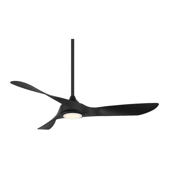
- Page 1 SWIRL Installation Instructions works with the Google Assistant...
- Page 2 Please read and review instructions before installation...
- Page 3 GENERAL INQUIRIES FAN SUPPORT For all questions about your ceiling fan please read all For fast service have the following information below included instructions, installation procedures, trouble- when you call: shooting guidelines and warranty information before starting installation • Model Name and Number For missing parts or general inquiries •...
- Page 4 SAFETY RULES For operation, maintenance, and troubleshooting information, visit http://waclighting.com/fan-support/ To reduce the risk of electric shock, ensure electricity has been turned off To avoid personal injury or damage to the fan and at the circuit breaker before beginning. other items, please be cautious when working around or cleaning the fan.
- Page 5 WAC. Substitution of parts WARNING: Do not operate fan unless fan blades are in place. or accessories not designated for use with this product by WAC could result Noise and fan damage can occur in personal injury or property damage and will void the warranty.
- Page 6 MOTOR Wi-Fi and Bluetooth enabled Compatible with our WAC app for unlimited control The WAC app synchronizes seamlessly with smart home devices you already own works with the Google Assistant APP DOWNLOAD WALL CONTROL REMOTE CONTROL...
-
Page 7: Table Of Contents
TABLE OF CONTENTS Package Contents Mounting Options Installing the Mounting Bracket Attaching the Fan Blades Hanging the Fan Making the Electrical Connections Installing the Optional Wall Control Finishing Hanging the Fan Installing the Adapter Plate Installing the Luminaire Module/Glass Controlling the Fan Reset App Instructions Accessories... - Page 8 TOOLS & MATERIALS REQUIRED Electrical tape Wire cutters Phillips screwdriver Step ladder NOTE: Before discarding packaging materials, be certain all parts have been removed. NOTE: Place the parts from the hardware bag into a small container to keep them from being lost. MAC ID IMPORTANT: Please make note of the MAC ID on the receiver and keep it in a safe place.
-
Page 9: Package Contents
PACKAGE CONTENTS Fan Blade RPL-F074-54-BD-** Canopy Ring RPL-CAN-RND-** Downrod Assembly Coupling Cover RPL-HGR-ASM-** RPL-F074-COUCVR-** Canopy Mounting RPL-CAN-RND-** Bracket Motor RPL-HGR-ASM-** Housing Hardware Bag Remote Control RPL-F074-PARTS RC20-WT Receiver Luminaire Module F-R3-074-054 Junction Box Safety Cable F4IN-120V-R1-30 Machine Screws (2) Flat Washer (1) Spring Washers (2) Spring Washer (1) Flat Washers (2) -
Page 10: Mounting Options
MOUNTING OPTIONS INSTALLING THE MOUNTING BRACKET Standard Ceiling Slope Ceiling To Switch To Switch (No Neutral) Caution: Remember to disconnect the power at the circuit breaker. (Ground) (Ground) (Hot) (Hot)/ *Bare or Switch *Bare or (Neutral) Green Green CAUTION: To prevent electrical shock, ensure electricity Secure the hanger bracket to the ceiling outlet box using has been turned off at the circuit breaker before beginning. -
Page 11: Attaching The Fan Blades
ATTACHING THE FAN BLADES Place the blade on the top of the housing. Align the holes in Flip the fan over and place on soft cloth or the foam in the blade with the fan motor assembly holes and secure with the carton to stabilize the fan. - Page 12 HANGING THE FAN Remove the hanger ball portion from the downrod/ hanger ball assembly by loosening Cross Pin the set screw in the hanger ball until the ball falls Downro freely down the downrod. Remove the pin from the downrod, then remove the hanger ball. Retain Hairpin Clip Set Screw the pin and hanger ball for reinstallation.
-
Page 13: Hanging The Fan
HANGING THE FAN Carefully lift the fan motor assembly up to the mounting bracket and seat the hanger ball in the mounting bracket (painted side face down), and canopy (opened side up) onto socket. Make sure the tab on the mounting bracket socket is the downrod. - Page 14 HANGING THE FAN Make sure you have the correct down-rod size prior to cutting said lead wire. Make sure the electrical supply wires, including the hanger bracket grounding wire and safety cable are pulled through the downrod, between the hanger bracket and the outlet box so that electrical connections can be made later.
- Page 15 HANGING THE FAN Mounting Bracket Receiver WARNING: Installation of this fan requires that a three-con- ductor cable (including ground and neutral wire) which should run between ceiling and wall outlet box. WARNING: Check to see that all connections are tight, including ground, and that no bare wire is visible at the wire nuts, except for the ground wire.
-
Page 16: Making The Electrical Connections
MAKING THE ELECTRICAL CONNECTIONS Connect the hanger ball/downrod assembly ground wire, mounting bracket ground wire and receiver ground wire to the ground wire in outlet box. Make sure all connections are made correctly or you will permanently damage the receiver. You may also refer to the labels on the receiver wires for direction on how to make proper connections. -
Page 17: Installing The Optional Wall Control
INSTALLING THE OPTIONAL WALL CONTROL NOTE: Wall control not included. A Bluetooth wall control accessory can be purchased separately. Skip this section if you did not purchase a wall control. NOTE: For multi-location wiring, skip to the next step. Connect the green wire marked “GROUND” from the wall control to the copper wire from the wall outlet box that feeds back to the circuit breaker –... - Page 18 INSTALLING THE OPTIONAL WALL CONTROL Wall Control 1 Wall Control 2 Wall Control 3 Install the wall control using the wiring diagram above. Individually pair each of the wall controls with the fan receiver using the pairing instructions in section 12.
-
Page 19: Finishing Hanging The Fan
FINISHING HANGING THE FAN Secure wire connectors with supplied wire ties. Install canopy to mounting bracket with the screw removed in section 2. Install canopy screw ring as shown. -
Page 20: Installing The Adapter Plate
INSTALLING THE ADAPTER PLATE Remove 1 screw from the mounting ring and loosen 2 others. Tighten the two mounting ring screws previously loosened and the one previously removed to secure adapter plate. F-074 L... -
Page 21: Installing The Luminaire Module/Glass
Install LED with the 3 previously removed screws. Raise PC shade up against the luminaire module and secure it to fan by turning PC Shade clockwise until snug. You are now ready to control your WAC Smart fan. F - 0 7 4 L... - Page 22 B: Fan On/Off, Speed Up/Down power on to the fan receiver. If you wish to pair your remote to another WAC Smart Fan or if you ever need to re-pair your remote to its original C: Season (Summer/Winter) fan, press and hold the light toggle and fan toggle for 4 seconds until Air-Gap Switch: Pull tab to power off in case of emergency.
-
Page 23: Controlling The Fan
CONTROLLING THE FAN Breeze Mode Controlling Multiple Fans with Remote or Wall Controls Your remote and wall controls are capable of controlling multiple fans. A remote or wall control has the ability to control Breeze Mode mimics the natural ebb and flow of winds in an unlimited number of fans with the only limitation being the nature by varying the fan speed. - Page 24 CONTROLLING THE FAN Fan On/Off Light On/Off Fan Direction Press and hold Press and hold Press and hold button for 4 seconds. button for 4 seconds. button for 4 seconds. Fan On/Off: Press and hold button for 4 seconds. The LED on the remote will flash green and all connected fans will beep to indicate the message has been received.
-
Page 25: Reset
You can toggle, and season button for 10 seconds or briefly depressing then use the WAC Fans app to connect your fan to the new net- the reset button on the fan’s receiver. The fan will emit three work. - Page 26 APPLICATION In addition to the included control, you can operate your fan with The WAC app will walk you through the main screen and show the WAC app. you how to create schedules, change fan speeds, dim the light, switch between Summer and Winter Modes, invite users, Upgradeable with Smart Features create groups and much more.
-
Page 27: Accessories
Compatible with WAC Smart Fans RC20- Bluetooth Remote Control 6 fan speeds, dims light to 1% 6 fan speeds, dims light to 1% WC20- Works in conjunction with WAC Smart Fan receiver Bluetooth Wall Control (not included) Coupler DC-** Connects two downrods... - Page 28 ACCESSORIES Product Model Description Downrod DR12-** 12” downrod DR18-** 18” downrod DR24-** 24” downrod All our downrods are 1” 1” O.D. and are threaded on the motor DR36-** 36” downrod end to create an extra layer of security to allow for adjustments in the field.
-
Page 29: Troubleshooting
TROUBLESHOOTING My Fan Will Not Start Check main and branch circuit fuses or circuit breakers. Check line wire connections to fan and switch wire connections in the switch housings. WARNING: Make sure the main power is turned off! My Fan is Noisy Allow for 24-hour break-in period. - Page 30 TROUBLESHOOTING My Fan is not producing Enough Air Movement If possible, please consider using a longer than included downrod. My remote or wall control is not controlling my fan Verify that the fan is receiving power by power cycling the fan. To do this: Cut power to the fan via standard On/Off wall switch, or the breaker if standard wall switch is not applicable.
- Page 31 What is Pairing? Pairing is the process of connecting your WAC remote or wall control to your fan. Your fan comes pre-paired to your included remote control. However, if you want additional controls for your fan or if you’re replacing a control, refer to the pairing and unpairing section of the instructions.
- Page 32 (o según el período de tiempo indicado en el material). Quedan of a defect in writing must be received by WAC within five (5) years from the date of excluidos de la garantía todos los componentes de terceros que tengan la garantía de purchase (or according period of time as outlined by material).
- Page 33 WAC doit recevoir un avis écrit du défaut dans un délai de cinq (5) ans à compter de la date d’achat (ou selon la période précisée dans les informations fournies).
- Page 34 F - 074L waclighting.com...
Need help?
Do you have a question about the SWIRL F-074L and is the answer not in the manual?
Questions and answers