Table of Contents
Advertisement
Quick Links
Advertisement
Table of Contents

Subscribe to Our Youtube Channel
Related Manuals for Abus Smartvest FUAA35000


Summary of Contents for Abus Smartvest FUAA35000
- Page 1 Smartvest User guide You can find important information and FAQs about this and other products online at: www.abus.com Version 1.5 English translation of the original German instruction manual. Retain for future reference. Back to Contents Back to Contents...
- Page 2 ABUS Security-Center GmbH is not liable or responsible for direct or indirect damage resulting from the equipment, performance and use of this product. No guarantee is made for the contents of this document.
- Page 3 English Explanation of symbols The triangular high voltage symbol is used to warn of the risk of injury or health hazards (e.g. caused by electric shock). The triangular warning symbol indicates important notes in this user guide which must be observed. This symbol indicates special tips and notes on the operation of the unit.
- Page 4 English Power supply • Only operate this device using a power source which supplies the grid voltage specified on the type plate. If you are unsure which voltage is supplied at the installation location, contact your energy provider. • Disconnect the device from the power supply before carrying out maintenance or installation work. •...
- Page 5 English Installation location/operating environment Place or mount the device on a steady, level surface and do not place any heavy objects on the device. Make sure that there is adequate ventilation (do not place the Smartvest on a shelf, thick carpet, bed or wherever the ventilation slits may be covered.
- Page 6 English Unpacking the device Handle the device with extreme care when unpacking it. Packaging and packaging aids can be reused and, as far as possible, should be sent for recycling. We recommend the following: Paper, cardboard and corrugated cardboard as well as plastic packaging items should be placed in the appropriate recycling containers.
-
Page 7: Table Of Contents
English Contents Device description .......................... 10 FUAA35000 Smartvest ......................10 FUHA35000 Wireless Socket ....................13 FUMK35000 Magnetic Contact ..................... 14 FUBW35000 PIR Motion Detector..................15 FURM35000 Smoke/Heat Detector ..................15 FUSG35000 Siren ......................... 16 FUBE35000/FUBE35001 Remote Key ................. 17 FUBE35010/FUBE35011 Control Panel ................18 FUWM35000 Flood Detector .................... - Page 8 English Configuration ..........................54 Configuration overview ......................55 Components .......................... 56 5.2.1 Pairing the camera ........................ 56 5.2.2 Pairing the wireless socket ....................56 5.2.3 Pairing the magnetic contact ....................57 5.2.4 Pairing the motion detector ....................57 5.2.5 Pairing the smoke/heat detector ................... 57 5.2.6 Pairing the siren ........................
- Page 9 English 5.7.5 Firmware update ........................78 5.7.6 Adopt time ..........................79 5.7.7 Daylight saving time ......................79 5.7.8 About ............................. 79 5.7.9 Additional modes ........................79 Technical data ..........................80 FURM35000A Smartvest Wireless Smoke/Heat Detector ............. 86 Introduction ..........................86 Safety information ........................
-
Page 10: Device Description
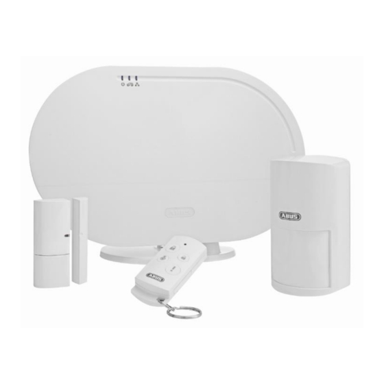
English 1. Device description This section contains descriptions of the Smartvest and all associated components. FUAA35000 Smartvest Front System is supplied with power Power LED Green No power supply System is “disarmed” The system is “disarmed” and there is a fault Yellow (e.g. - Page 11 English Under side To reset passwords to the default settings (123456) and network settings to DHCP: • While the system is in operation, press and hold the reset button for >10 seconds using a paper clip. The power LED will go out and a continuous tone will sound.
- Page 12 English Rear 6 x AA (1.5 V) batteries for backup power supply (approx. 5h battery life) Changing the battery Battery Push the clips to open the battery compartment cover. operation Remove the six dead AA (1.5 V) batteries from the compartment and replace with six new AA (1.5 V) batteries.
-
Page 13: Fuha35000 Wireless Socket
English FUHA35000 Wireless Socket Schuko socket type F (CEE 7/4). Can be used in the following countries: Schuko socket Germany, Austria, Sweden, Netherlands Wireless socket is activated; power is being transmitted. Wireless socket is ready and activated; power is not being transmitted to the appliance. Blue Flashing Wireless socket is starting up... -
Page 14: Fumk35000 Magnetic Contact
English FUMK35000 Magnetic Contact Contains a wireless component Transmitter component Mounted on window frame Magnetic contact is closed Signal LED Blue Flashing Magnetic contact is opened 1x 3 V button battery (CR2032) for power supply (up to one year battery life). The Smartvest App warns you when the battery is low. -
Page 15: Fubw35000 Pir Motion Detector
English FUBW35000 PIR Motion Detector Catch Catch for removing the rear panel Button for manual pairing with the Smartvest Pair button Activate test mode: press for 5 s Deactivate test mode: press for 5 s Tampering Tampering contact for alarming in the event of unwanted removal contact 3 x AA (1.5 V) batteries for power supply (up to two years battery life) The Smartvest App warns you when the battery is low. -
Page 16: Fusg35000 Siren
English FUSG35000 Siren LED flashes (according to setting) in the event of an alarm and to LED chamber acknowledge changes to the siren settings. If the system status changes, the siren will flash two times. Loudspeaker Siren loudspeaker with an adjustable volume of 80 db or 100 db. Pair button Button for manual pairing with the Smartvest Tampering... -
Page 17: Fube35000/Fube35001 Remote Key
English FUBE35000/FUBE35001 Remote Key Signal LED Blue Flashing Acknowledges when button is pressed Button for arming the Smartvest Arm button Press and hold for five seconds to part set Disarm button Button for disarming the Smartvest Camera button Button to start recording for connected cameras Panic button Button for triggering the panic alarm (press for 3 seconds) 1x 3 V button battery (CR2032) for power supply (up to two years battery life) -
Page 18: Fube35010/Fube35011 Control Panel
English FUBE35010/FUBE35011 Control Panel Arm button Button for arming the Smartvest Button for disarming the Smartvest Verification is required after pressing (PIN Disarm button or RFID Chip). Part Button for part setting the Smartvest. set button Panic button Button for triggering the panic alarm (press and hold for five seconds). - Page 19 English Tampering Tampering contact for alarming in the event of unwanted removal contact Cabling for the power supply Cabling Control panel sounder Sounder Note The exact reaction caused when a button is pressed depends on the app settings. Refer Section 5.7, Advanced settings for the arm and disarm buttons, and Section 5.4, Hotkeys...
-
Page 20: Fuwm35000 Flood Detector
English FUWM35000 Flood Detector Mount These slots are for fixing the Flood Detector to the wall. slot 4 x AA (1.5 V) batteries for power supply (up to two years battery life) The Smartvest App warns you when the battery is low. Follow the instructions in the app. -
Page 21: Fube35020 Wireless Button
English FUBE35020 Wireless Button Configurable for two switch commands Button Short press (< 1 s) Long press (approx. 5 s) LED ring Orange LED lights up when a switch command (short/long) is sent. Bracket slot These slots are for fixing the Wireless Button to the wall bracket. 1 x CR2032 (3 V) battery as power supply (approx. -
Page 22: Fusg35010 Wireless Door Bell
English FUSG35010 Wireless Door Bell Loudspeaker Door bell loudspeaker Lights up while playing a tune High (approx. 80 dbA) Medium (approx. 70 dbA) Volume button Low (approx. 60 dbA) Mute For testing the tune: (The actual configuration takes place in the Smartvest App) Tune button Tune 1–4 = door bell tune Tune 5 = Alarm tone (in the event of an alarm only) -
Page 23: Fuem35000 Vibration Detector
English FUEM35000 Vibration Detector Contains a wireless component Transmitter component Mounted on window frame Signal LED Blue Flashing Vibration Detector triggers 1x 3 V button battery (CR2032) for power supply (up to one year battery life). The Smartvest App warns you when the battery is low. Follow the instructions in the app. -
Page 24: Start-Up
English 2. Start-up Before installing your Smartvest and detector, follow the steps below to start up your Smartvest and pair components with the Smartvest. Installing the Smartvest App For the Smartvest, there is an app called “Smartvest” available for download from the Google Play Store and the iOS App Store. This app can be used on smartphones and tablets, referred to as “end devices”... - Page 25 English Select Select your Smartvest from the list. If you want to link the Smartvest from another network or the Smartvest is not found, enter the DID manually. All further entries must then also be made manually. Device security code The standard security code “123456”...
- Page 26 English After restoring the factory settings or resetting the password (in the case of location data) (On site) If no data has been entered. All subsequent input from any other system users, for example, will not be acknowledged. End setup Tap “Save”...
-
Page 27: Pairing Components
English Pairing components Open the Smartvest App and connect to the Smartvest. Note The settings for your components can be found in Section 5.3 Setting up components. Carry out the following steps: Open Smartvest settings To access the Smartvest settings, tap the settings symbol the bottom left-hand corner of the operation view. - Page 28 English Pairing components Enter a name for the component. Note The name must consist of no more than 15 characters. Additional characters will be automatically deleted after saving. Open the room list and select the room where the component is installed.
-
Page 29: Removing Components
English Removing components Removing components Open the component list and... For Android: … slide the components to the right-hand edge of the screen and confirm removal For iOS: … slide the components to the left-hand edge of the screen and press “Delete”... - Page 30 English App security Tap “Change app PIN” to enter your own app PIN. During the initial setup, the standard app PIN is “123456”. Important If the app PIN is enabled, you will be asked to enter this each time you start the app on your end device. If you have forgotten your app PIN, you must delete the app and reinstall it.
-
Page 31: Installation
English 3. Installation This section describes how to install the Smartvest and the associated components. Please refer to Sections 4 and 5 when operating and adjusting the settings for the Smartvest via the Smartvest App. Warning When using adhesive pads, ensure that the surface below is clean, abrasion-resistant and dry. -
Page 32: Fuha35000 Wireless Socket
English Wall installation Stick the Smartvest drilling template to the desired installation location. Use a spirit level to ensure the drilling template is straight. Drill holes in the specified positions and insert the screw anchors provided. Screw the screws provided into the screw anchors so that the heads protrude by around 6 mm, then mount the Smartvest. - Page 33 English • You can either install the magnetic contact on the top or the side of the window. If you install the magnetic contact on the underside of the window, the magnetic contact may not trigger if the window is tilted (not recommended). Installation with adhesive pads 1.
-
Page 34: Fubw35000 Pir Motion Detector
English FUBW35000 PIR Motion Detector The motion detector is only suitable for indoor use. For further information, please refer to the safety instructions relating to installation location and operating environment. General installation instructions • Install the motion detector 2–2.5 m above the ground for a range of 12 m. •... -
Page 35: Furm35000 Smoke/Heat Detector
English Drill installation without bracket 1. Press the catch on the underside of the motion detector and remove the motion detector’s rear panel. 2. Use the holes provided on the inside of the rear panel as a drill template for wall or corner installation. -
Page 36: Fube35000/Fube35001 Remote Key
English • When choosing the installation location, ensure that the siren can be seen and heard from a long distance. • Pressing the tamper contact for the first time activates the siren. After this, if the tamper contact is triggered, the tamper alarm is triggered. Drill installation 1. - Page 37 English General installation instructions Note The tamper contact may be triggered when installing the control panel. In order to prevent unwanted alarms in this case, you can activate maintenance mode in the app’s advanced settings. (See Section 5.7 Advanced settings) Remove the plastic strip protruding from the battery compartment in order to switch on the control panel.
-
Page 38: Fuwm35000 Flood Detector
English FUWM35000 Flood Detector Note The Flood Detector is only suitable for indoor use. For further information, please refer to the safety instructions relating to installation location and operating environment. Drill installation Ensure that your Smartvest Flood Detector has batteries as a backup power supply before installation. 1. -
Page 39: Fube35020 Wireless Button
English 3.10 FUBE35020 Wireless Button Note The Wireless Button is only suitable for indoor use. For further information, please refer to the safety instructions relating to installation location and operating environment. Drill installation using bracket 1. With the help of the bracket, mark two bore holes on the wall (“UP” denotes which way is up). Drill holes in the specified positions and insert the screw anchors provided. -
Page 40: Fusg35010 Wireless Door Bell
English 3.11 FUSG35010 Wireless Door Bell Note The Wireless Door Bell is only suitable for indoor use. For further information, please refer to the safety instructions relating to installation location and operating environment. General installation instructions Note If you are using the door bell as a sounder in the event of an alarm, please ensure that the door bell is not mounted somewhere readily accessible as it does not feature any tamper protection. - Page 41 English Installation with adhesive pads 1. Please clean the areas where you would like to attach the adhesive pads first. 2. Affix the two adhesive pads to the underside of the Vibration Detector. 3. Secure the Vibration Detector in the desired position. Installation with screws 1.
-
Page 42: Operation
English 4. Operation The Smartvest App is divided into two basic menus, operation and configuration. This section will show you how to operate the Smartvest via the Smartvest App. Please refer to Section 5 to find out how to configure the Smartvest. The following functions are available in the operation menu: •... -
Page 43: Navigation Bar And Footer
English Navigation bar and footer Open the Smartvest App and connect to the Smartvest. Navigation bar View The individual menu items are shown in the navigation bar at the top. The menu you are currently viewing is highlighted. Switching menu You can switch between the individual menus by “swiping”... -
Page 44: Overview
English Overview Status display Three different symbols are used to represent the different Smartvest statuses in the status display. The current status is marked in colour, with the relevant text shown below. You can change the status by dragging to the left or right or, alternatively, by tapping the desired status. - Page 45 English Hotkeys There are two pre-configured hotkeys – panic and camera – below the status display, which you can tap and enable in the overview. These two hotkeys are also found on the FUBE35000 Remote Key and can be operated from there. Standard: All actuators are triggered (e.g.
-
Page 46: Hotkeys
English Hotkeys Application examples Hotkeys enable straightforward activation of various components with just the touch of a button. If necessary, you could even configure a hotkey (panic) to activate the siren, for example, which would scare off the intruder before they break in. Alternatively, you could create a user-defined hotkey to activate one or several wireless sockets and switch your home lighting on and off by tapping the hotkey. -
Page 47: Rooms
English Rooms Room overview In the room overview, all rooms with at least one added component are shown. A maximum of two components are shown under the room name. Room details Tap the desired room to open the individual room overview. All components which have been added to the room are then listed. -
Page 48: Cameras
English Cameras (TVAC16000/TVAC19000/TVAC19100) (PPIC32020/PPIC3x520/PPIC42520/PPIC44520/PPIC31020) Camera overview Up to four cameras can be displayed in the camera overview. In the settings, you can add four cameras in the camera overview or edit the settings for the cameras already available. You can access the live view with the various camera functions by tapping the relevant camera. - Page 49 English TVAC19100/PPICx4520 Live view Move two fingers away from each other on the screen to zoom in on the camera image. Actions Activate microphone Tap this button to listen to the camera’s recorded audio. Snapshot Tap this button to save a snapshot on your end device.
-
Page 50: Contacts
English PPIC31020 Functions Auto-Zoom An: Das Livebild wird automatisch herangezoomt. Aus: Das Livebild wir vollständig angezeigt Note: Live view is only available if the flap is open Contacts Contact overview Up to four contacts can be displayed in the contact overview. Two pre-configured contacts –... -
Page 51: Events
English Make calls Tapping a contact’s number automatically brings up the telephone view for your end device, with the relevant contact’s number pre- dialled. To make the call, you need to tap your end device’s call button. Important The pre-configured contacts – emergency and police –... - Page 52 English Via iTunes synchronisation Search Tap the search symbol in the bottom left-hand corner to search events within a specific time period. Tap “Search” to carry out the search or the arrow symbol to return to the event overview. Updating manually You can update the event list manually by swiping downwards.
-
Page 53: Alarm View
English Alarm view Alarm view The alarm view opens when an alarm is triggered, if: • the Smartvest App is already open • the Smartvest App is opened after the alarm • the Smartvest App is opened by tapping the alarm’s push notification. -
Page 54: Configuration
English 5. Configuration The Smartvest App is divided into two basic menus, operation and configuration. This section will show you how to configure the Smartvest via the Smartvest App. Please refer to Section 4 to find out how to operate the Smartvest. The following can be carried out via the configuration menu: •... -
Page 55: Configuration Overview
English Configuration overview Configuration overview The Smartvest settings, contacts and manual are displayed in the configuration overview. Smartvest settings Enter the settings password (default: “123456”) to access all Smartvest settings options. The settings password must be entered to change the following settings: •... -
Page 56: Components
English Components Component overview Tap “Components” to access the component overview. All paired components and the associated rooms are displayed in the overview. Pairing components Tap the plus sign to add a component. Select the relevant component from the component list. 5.2.1 Pairing the camera Note If you have connected the camera to the same... -
Page 57: Pairing The Magnetic Contact
English 5.2.3 Pairing the magnetic contact • Section 5.2 Admin area → Components → Plus sign • Enter a name for the component. • Open the room list and select the room where the component is installed. Tap the arrow to return to the settings. -
Page 58: Pairing The Siren
English 5.2.6 Pairing the siren • Section 5.2 Admin area → Components → Plus sign • Enter a name for the component. • Open the room list and select the room where the component is installed. Tap the arrow to return to the settings. •... -
Page 59: Pairing The Flood Detector
English 5.2.9 Pairing the Flood Detector • Section 5.2 Admin area → Components → Plus sign • Enter a name for the component. • Open the room list and select the room where the component is installed. Tap the arrow to return to the settings. -
Page 60: Pairing The Vibration Detector
English 5.2.12 Pairing the Vibration Detector • Section 5.2 Admin area → Components → Plus sign • Enter a name for the component. • Open the room list and select the room where the component is installed. Tap the arrow to return to the settings. -
Page 61: Setting Up The Wireless Socket
English 5.3.2 Configuration of the wireless socket Select the components you want to configure from the component overview. Name Enter a name for the component. Auto off after scenario Specify how long the wireless socket should remain activated after a scenario has been activated. Room Open the room list and select the room where the wireless socket is installed. -
Page 62: Setting Up The Smoke/Heat Detector
English 5.3.5 Configuration of the smoke/heat detector Select the components you want to configure from the component overview. Name Enter a name for the component. Room Open the room list and select the room where the component is installed. Tap the arrow to return to the settings. -
Page 63: Setting Up The Remote Key
English 5.3.7 Configuration of the Remote Key Select the components you want to configure from the component overview. Name Enter a name for the component. Room Open the room list and select the room where the Remote Key is assigned. Tap the arrow to return to the settings. -
Page 64: Setting Up The Flood Detector
English • The number of RFID chips previously paired is displayed on the control panel. • If the pairing of the chip was unsuccessful, a single long signal tone is emitted. • To exit the settings, press the settings button again. Note A maximum of eight RFID chips can be paired. -
Page 65: Setting Up The Wireless Button
English 5.3.10 Configuration of the Wireless Button Select the components you want to configure from the component overview. Name Enter a name for the component. Room Open the room list and select the room where the Wireless button is installed. Tap the arrow to return to the settings. -
Page 66: Setting Up The Vibration Detector
English 5.3.12 Setting up the Vibration Detector Select the components you want to configure from the component overview. Name Enter a name for the component. Sensitivity Define the sensitivity at which the detector triggers High = Maximum sensitivity level Medium = Medium sensitivity level Low = Low sensitivity level Alignment Specify “horizontal”... -
Page 67: Setting Up The Camera
English 5.3.13 Configuration of the camera Camera Name Enter a name for the component. DID = Device ID for the camera Read the camera’s DID number here. Security code Entering the camera’s security code Note: The password length is limited to 15 characters Advanced settings Open the advanced settings by entering the camera’s admin code (default setting: 123456) - Page 68 English technologies for audio and video may result in asynchronous transmission as a result of different network traffic. Environment mode • Here, you have the option to choose between the interior (50 Hz), interior (60 Hz) and exterior network frequency. •...
-
Page 69: Hotkeys
English Note: When formatting the SD card, all data will be deleted. Please save the data before formatting. Activating the circular buffer If this function is activated, the newest recordings overwrite the oldest ones once the SD card is full. Device information Here you can read the firmware version, as well as the total storage and available storage space. -
Page 70: Scenarios
English Scenarios 5.5.1 Application examples – Basics Scenarios allow you to automate certain actions in your home; for example, you can use a motion detector when a room is entered or a magnetic contact when a door is opened to switch on a light source connected to a wireless socket. You could also use a motion detector or magnetic contact to start a camera recording, which allows you to always have an overview of who has entered your house and when. -
Page 71: Open/Closed Magnetic Contact Scenario
English 5.5.2 Open/closed magnetic contact scenario Scenarios triggered by a magnetic contact can now be differentiated by whether they are open/closed. This requires you to identify a separate scenario for each of the statuses “open” and “closed”. The following selection menu allows you to define the “If ..., Then”... -
Page 72: Door Bell Alarm Panel Scenario
English 5.5.4 Door bell alarm panel scenario The door bell for the alarm panel can now be triggered in the Scenario settings. The door bell is a two-tone sequence of the alarm panel piezo, which is then triggered when activating the scenario. 5.5.5 Wireless Button scenario The Wireless Button features the following two possible actions:... -
Page 73: Schedules
English Schedules Application examples Schedules allow you to automate certain actions in your home as well as providing presence simulation. You can store schedules for each wireless socket to activate light sources that are connected to a wireless socket and simulate a presence when you are away, while on holiday for example. You could also connect your Christmas lights to a wireless socket and activate these at night-time only using a schedule. -
Page 74: Advanced Settings
English Advanced settings 5.7.1 Network settings The Smartvest is set to DHCP by default. This means that the Smartvest is automatically assigned an IP address, subnet mask, gateway and DNS server by your router. Should you wish to enter these manually, switch DHCP to “Off” and enter your own details. -
Page 75: Status Configuration
English With other end devices, you must change the device security code in the general settings (see Section 2.5 General settings) before you next log in. Password for settings Enter the old password for settings and then the new password. Confirm this again, then tap “Save”. - Page 76 English Part set Select the actuators and sensors you would like to trigger and/or detect in “Part set” status. Exit delay Activate the exit delay and configure the delay time so you have enough time to leave the house after arming the Smartvest. The exit delay applies for both “Armed”...
-
Page 77: Notifications
Germany GmbH, Office Frankfurt, Mainfrankenpark 53, 97337 Dettelbach. The service is used at your own risk. ABUS Security-Center GmbH & Co. KG, Linker Kreuthweg 5, 86444 Affing, Germany shall not assume any liability for any possible damage caused as a result of using the service. -
Page 78: Firmware Update
English Selecting a notification type It is now possible to set the notification type and language in the Notifications settings. Notification selection You can now select or deselect individual groups of notifications. The Smartvest adopts the new settings once the “Save” button has been pressed. -
Page 79: Adopt Time
English 5.7.6 Adopt time Tap “Adopt time” to transfer the current time zone and time from your smartphone to the Smartvest. Note Before adopting the time, please ensure that the “Summertime” slide control has been correctly set (see following point). 5.7.7 Daylight saving time Activate summer time, to switch the time schedules from normal time to summer time. -
Page 80: Technical Data
English Remote mode In “Remote Mode”, app functionality is limited to Remote Key functions. This is suitable for users who should only be given access to the basic functions e.g. children. Remote access for service The app now has a service access function to facilitate rapid analyses when calling our customer service team. - Page 81 English Model number FUHA35000 Wireless Socket Schuko plug on device (type: F); Schuko socket on Connections device (type: F) Operating temperature °C 0–35 Frequency 868.3 Weight Dimensions 55 x 99 x 31 Max. humidity Range approx. 30 depending on the local conditions Tamper monitoring Switching power <...
- Page 82 English Frequency 868.3 Weight Dimensions 61 x 110 x 52 Max. humidity Wall installation Installation Height > 2 m Horizontal: 105° PIR angle of view Vertical: 45° Range approx. 30 depending on the local conditions Tamper monitoring Signal check FURM35000 – Smoke/Heat Detector Model number Alarm muting Battery...
- Page 83 English FUSG35000 – Siren Model number Battery 4 x C (1.5 V) Battery life Ø 2 years Operating temperature °C -10–50 Frequency 868.3 Weight Luminous colour Light source Dimensions 112 x 300 x 102 Max. humidity Installation Wall installation in protected outdoor area. Range approx.
- Page 84 English FUBE35010/FUBE35011 – Control Panel Model number Battery 4 x AA (1.5 V) Battery life Ø 1 year Operating temperature °C 0–40 Frequency 868.3 Weight Dimensions 140 x 120 x 30 Max. humidity 93 % Installation Wall installation indoors Range approx.
- Page 85 English FUBE35020 – Wireless Button Model number Battery 1 x CR2032 (3 V) Battery life Ø 1 year Operating temperature °C 0–40 Frequency 868.3 Weight Dimensions 70 x 30 x 10 Max. humidity Installation Wall or adhesive installation indoors Range approx.
-
Page 86: Furm35000A Smartvest Wireless Smoke/Heat Detector
English Max. humidity Installation Wall installation indoors Range approx. 30 depending on the local conditions Tamper monitoring Signal check 7. FURM35000A Smartvest Wireless Smoke/Heat Detector 0359 0359-CPR-00493 EN 14604:2005/AC:2008 Introduction Information on user guide Dear Customer, Thank you for choosing our product and putting your trust in us. You’ve made a good choice. This smoke alarm device (hereinafter referred to as “detector”... -
Page 87: Safety Information
English Limitation of liability Your rights are limited to the repair or replacement of this product in its as-delivered condition. ABUS Security-Center does not assume liability for any special, incidental or consequential damages, including but not limited to accrued loss of profit or earnings, loss or recovery of data, costs for replacement... -
Page 88: Scope Of Delivery
Do not, on any account, open or repair the device. Failure to observe this instruction will invalidate the warranty. Do not use the device if it has been dropped or damaged in any other way. Scope of delivery • ABUS smoke alarm device including batteries • User guide • Installation material... -
Page 89: Behaviour In Case Of Alarm
English Particularly high electromagnetic radiation could impair the function of the detector. For this reason, do not install the detector near magnets or devices which produce electromagnetic radiation. The smoke alarm device operates in accordance with the optical principle (photoelectric reflection) and features a measurement chamber in which infiltrating smoke particles are measured. -
Page 90: Installation And Start-Up
English Where smoke alarm devices should not be installed Outside (use only in closed rooms) In rooms in which the alarm could be triggered by disturbance variables (steam, condensation, “normal” smoke, vapour, dust, dirt or grease) Next to an air duct or similar ventilation opening (draughts) In areas in which the temperature can fall below 0 °C or rise to over 40 °C On unstable surfaces with designs that render them unsuitable for installation with screw anchors... - Page 91 English Test the functionality of the detector after installation without fail. A regular test is also recommended. Keep the device at arm’s length to protect your hearing. To carry out a test, hold the Test button down for just 3-5 seconds. Holding the Test button down for 15 seconds will reset the smoke detector to the factory default settings.
- Page 92 English Test alarm triggered by remote notification Carry out the test as described in the “Testing the device electronics” section. If additional wireless smoke/heat detectors are connected to Smartvest, they will be notified of the test at this point and confirm the test for 60 seconds. A loud, pulsing alarm tone sounds and the red LED flashes at the same time at short intervals.
-
Page 93: Care And Maintenance
English Care and maintenance What should you do in the event of a false alarm? Possible reasons for a false alarm are: Welding and cutting work, soldering and other high- temperature work, sawing and grinding, dust from construction work or cleaning, extreme electromagnetic effects, and temperature fluctuations which lead to condensation of the humidity in the detector. -
Page 94: Warranty
Declaration of Conformity text can be found at: www.abus.com/product/Itemnumber (‘Item number’ in the link to be replaced with the article number of the enclosed product[s]) It can also be obtained at the following address: ABUS Security-Center GmbH & Co. KG, Linker Kreuthweg 5, 86444 Affing, GERMANY... -
Page 95: Declaration Of Performance
This smoke alarm device is tested and certified as a building product in accordance with regulation EU 305/2011. Production is monitored by regular and independent inspections for continued compliance with legal and standard specifications. Declaration of performance FURM35000A#1115 can be found here: www.abus.com/ger/Service/Leistungserklaerungen Back to Contents Back to Contents...
Need help?
Do you have a question about the Smartvest FUAA35000 and is the answer not in the manual?
Questions and answers