Table of Contents
Advertisement
Quick Links
Advertisement
Table of Contents

Subscribe to Our Youtube Channel
Related Manuals for Vents VUT 300 E2V EC


Summary of Contents for Vents VUT 300 E2V EC
- Page 1 OperatiOn Manual air supply and exhaust unit with heat recovery Vut 300 e2V eC...
-
Page 2: Table Of Contents
Vut 300 e2V eC COntents Introduction Purpose Delivery Package Designation key Main Technical Data Safety Requirements Design and Operating Principle Installation and Setup Condensate Drainage Connection to power mains Unit control Technical Maintenance Fault Handling Storage and Transportation Regulations Manufacturer’s Warranty... -
Page 3: Introduction
The present operation manual consisting of the technical details, operating instructions and technical specification covers the installation of VUT 300 E2V EC heat-recycling air supply and exhaust units of VENTS series (hereinafter the Unit). purpOse The unit is heat-recycling device designed as an essential element of energy-saving systems in buildings and structures. -
Page 4: Designation Key
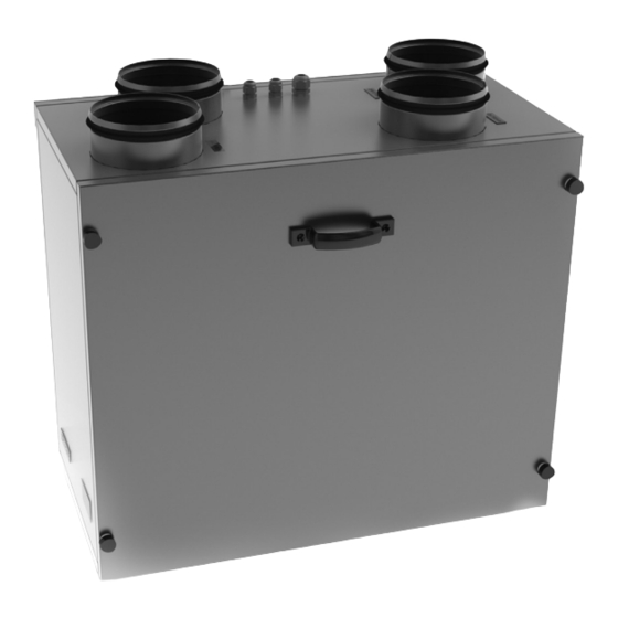
Vut 300 e2V eC designatiOn key VUT 300 Motor Type Electronically commutated Spigot Arrangement V - vertical Number of Heating Coils Electric heater Air capacity, m³/h Unit Type VUT - heat recovery ventilation Main teChniCal data The unit is designed for operation in an enclosed area at ambient temperatures from +1 °C to + 40 °C at relative humidity of up to 80%. - Page 5 Fig. 1. Outside and Connecting Dimensions of the Unit...
- Page 6 Vut 300 e2V eC Table 1 . Technical Parameters Model VUT 300 E2V EC Ventilation Mode Speed 1 Speed 2 Speed 3 Supply Voltage, V/50 Hz 1 ~ 230 Maximum Fan Power, W Fan Current, A Electric Heater Power, kW...
-
Page 7: Safety Requirements
safety requireMents Installation and operation of the unit shall be subject to the present Operation Manual and the all appliable local building, fire safety, technical and electric regulatory documents. The unit must be properly earthed. Prior to connecting the unit to the power mains check for visible damage as well as for any foreign objects in the fan casing which may damage the impeller blades If necessary, contact the service centre. -
Page 8: Installation And Setup
Vut 300 e2V eC min 1m Fig. 2. Design and Operating Logic installatiOn and setup Ensure convenient access for maintenance, servicing or replacement operations, required for the unit installation. The wall intended for unit installation must be smooth. Any surface irregularities will lead to unit casing skew and may prevent the unit from operating properly. - Page 9 The unit is mounted onto the wall using anchor bolts - see Fig. 3. Anchor bolt Fig. 3. Unit Installation The wall-mounted control panel is installed as follows: Lift the clips through the access holes in the bottom of the wall-mounted control panel (Fig.
-
Page 10: Condensate Drainage
Vut 300 e2V eC +24V data2/B data1/A Fig. 5. Fixing Back Cover to the Wall COndensate drainage min 3° CONDENSATE min 3° DRAIN TUBES min 3° min 3° CONNECTION PIPES U-trap SEWAGE COLLECTION SYSTEM Fig. 6. Condensate Removal The condensate drip pan installed in the heat recovery section has pipes for extracting the condensed fluid outside the unit. -
Page 11: Connection To Power Mains
The condensate removal system is designed for indoor operation at ambient temperatures above 0 °C. If the expected air temperatures are below 0 °C, the condensate drainage system must be equipped with heat insulation and pre-heating facilities. COnneCtiOn tO pOWer Mains disconnect the unit from the power supply prior to any maintenance or repair. -
Page 12: Unit Control
Vut 300 e2V eC The damper actuator is connected to terminals X3:5, X3:6 and X3:7 of terminal block X3. The same contacts can be used for parallel connection of one more damper. The additional contacts are connected according to the wiring connection diagram (Fig. 8). The wires are routed into the terminal box through a sealed lead-in in the cover. - Page 13 When the unit is off (Fig. 10) the wall-mounted control panel display indicates: Room temperature; Day; Time; Deactivated status In the TEH blowing mode indicators (blowing) are on as well as the blowing countdown (minutes : seconds). Fig. 10. Panel display in the OFF mode When the unit is on (Fig.
- Page 14 Vut 300 e2V eC attentiOn! upon deactivation with a working heater the unit continues operation for an additional 2 minutes to allow heater cooling. this is confirmed by the indicator. timer. The timer enables automatic switching of the fans to maximum speed with automatic reversion after a selected period of time (20-60 minutes).
- Page 15 To change the supply fan power press and hold the button and press the button to increase the speed or press the дbutton to decrease it. Each press of the buttons increases or reduces the supply fan power in 1 % increments.
- Page 16 Vut 300 e2V eC Press the button to display the controller circuit execution code and the firmware version code on the wall-mounted control panel screen (Fig. 15). To exit the duct temperature sensor setup mode press the button. Fig. 15. Firmware Version 5.
- Page 17 7. scheduled Operation Mode. To activate the scheduled operation mode press and hold the button, and then press button on the wall-mounted control panel. The scheduled operation mode is confirmed by the indicator on the display screen. To deactivate the scheduled operation mode press and hold the button, and then press button on the wall-mounted control panel.
- Page 18 Vut 300 e2V eC Table 3 . Sample programming sequence Entry Number Start Heater Start Heater Start Heater Start Heater Mode Mode Mode Mode Time Status Time Status Time Status Time Status 07:00 2 speed 08:00 1 speed 17:00 2 speed...
-
Page 19: Technical Maintenance
teChniCal MaintenanCe The unit requires maintenance works 3-4 times per year. Maintenance includes regular cleaning and the following operations: 1. filter maintenance (3-4 timed per year). Dirty filters increase air resistance in the system and reduce supply air volume. Clean the filters as required but at least once in 3-4 months. - Page 20 Vut 300 e2V eC Fig. 19. Heat exchanger ad fitler maintenance...
- Page 21 Fig. 20. Control unit maintenance...
-
Page 22: Fault Handling
Vut 300 e2V eC fault handling troubleshooting and fault handling Trouble Possible Reasons Fault handling Make sure that the unit is properly Fan (Fans) will The unit is not connected to the connected to the power mains and not start power mains. -
Page 23: Storage And Transportation Regulations
stOrage and transpOrtatiOn rules Store the unit in the manufacturer’s original packing box in a closed ventilated premise with temperature range from +10°C to +40°C and relative humidity less than 80% (at +20°C). Vapours or particles which can cause corrosion or damage the insulation or connection tightness are not allowed in the storage environment. -
Page 24: Acceptance Certificate
Vut 300 e2V eC aCCeptanCe CertifiCate the air handling unit with heat recovery Vut 300 e2V eC has been duly certified as serviceable. We hereby declare that the product complies with the essential protection requirements of Electromagnetic Council Directive 2004/108/EC, 89/336/EEC and Low Voltage Directive 2006/95/ EC, 73/23/EEC and CE-marking Directive 93/68/EEC on the approximation of the laws of the Member States relating to electromagnetic compatibility. - Page 25 V79ENG-02 2012...
Need help?
Do you have a question about the VUT 300 E2V EC and is the answer not in the manual?
Questions and answers