Table of Contents
Advertisement
Quick Links
Advertisement
Table of Contents

Subscribe to Our Youtube Channel
Related Manuals for Vents KSD 250-6E


Summary of Contents for Vents KSD 250-6E
- Page 1 User’s manual...
-
Page 2: Table Of Contents
page Purpose CONTENTS Delivery set Technical data Safety requirements Fan design TSC module description and functioning Mounting and set-up Connection to power mains Fan options Wiring diagrams Technical maintenance Storage regulations Manufacturer's warranty Troubleshooting Acceptance certificate Warranty card... -
Page 3: Purpose
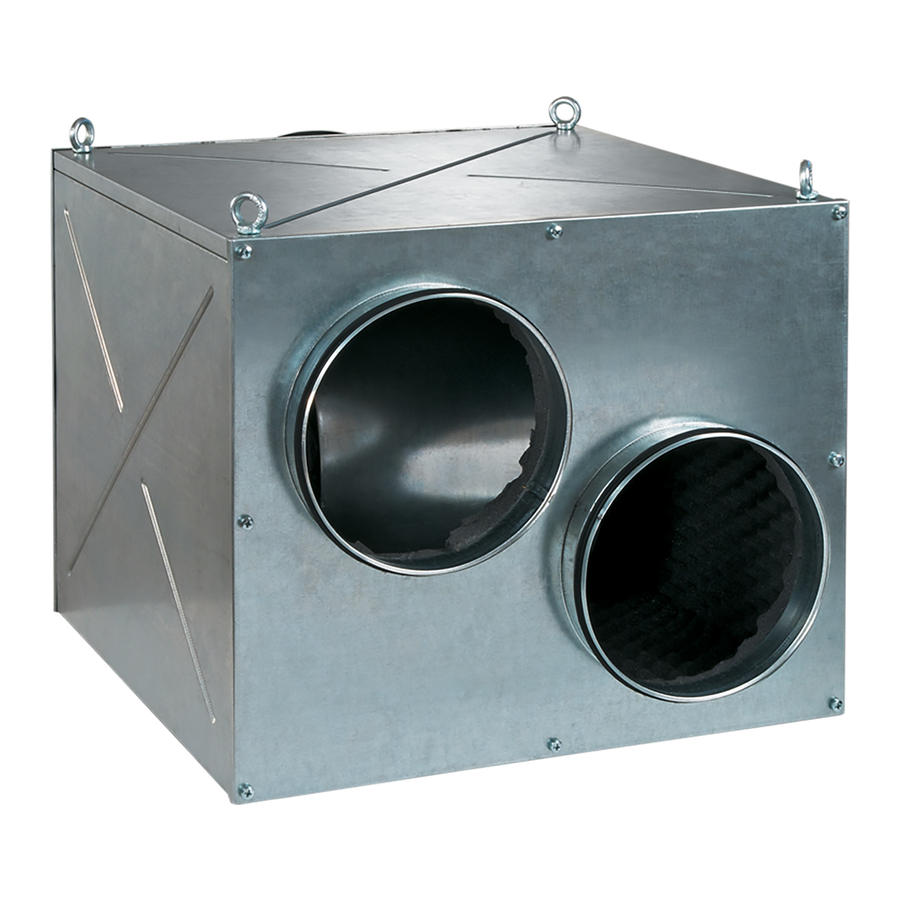
The centrifugal electric fan VENTS KSD enclosed in a metal sound-insulated casing with PURPOSE a double-inlet Ø 180 to 320 mm impeller and forward curved blades, hereinafter the fan, is designed for supply and exhaust ventilation of domestic, public and industrial premises with high sound attenuation requirements. - Page 4 ХХХ ХХХ /ХХХ Х - Х Х Х Х Х DESIGNATION Casing insulation _ : PU foam insulation. K1: mineral wool insulation. Power cable with IEC C14 plug. Temperature and speed controller type U: speed controller with electronic thermostat and temperature sensor integrated into the air duct.
- Page 5 Overall and connecting dimensions of KSD fan with one intake and one exhaust spigot with two intake spigots and one exhaust spigot Dimensions [mm] Weight Modell [kg] KSD 250-6E 21,5 KSD 250-4E 21,5 KSD 250 С-6E 30,8 KSD 250 С-4E...
- Page 6 1 - Fan casing 2 - Sound-insulating layer 3 - Intake spigot 4 - Exhaust spigot 5 - Terminal box 6 - Fan grounding 7 - Impeller 8 - Mounting nut 9 - Speed control knob 10 - Temperature control knob 11 - Fan operation indicator 12 - Thermostat indicator 1 - Fan casing...
- Page 7 KSD fan mounting and operation example 1хD 3хD General mounting recommendations for KSD fans...
-
Page 8: Safety Requirements
Do not operate the fan outside the temperature range stated in the user's manual. Do not operate the fan in aggressive or explosive environments. DO NOT The fan must be mounted and connected to power supply only by properly qualified personnel SAFETY in compliance with acting regulatory documents. -
Page 9: Tsc Module Description And Functioning
Electronic temperature and speed controller TSC MODULE Available in KSD U, KSD U1, KSD Un, KSD U1n. DESCRIPTION The electronic speed and temperature control module is designed for duct temperature control and automatic variable speed control (air flow control) depending on the temperature. FUNCTIONING KSD U, KSD U1 models are equipped with a built-in temperature sensor and the KSD Un, KSD U1n models are equipped with an external temperature sensor fixed... - Page 10 The motor switches to high speed as the air temperature exceeds 2 °C above the set thermostat set point. The motor revers to the pre-set lower speed as the air temperature drops below the thermostat set point. This pattern is used to keep air temperature to within 2 °C.
- Page 11 Example of the temperature-based feedback delay for the temperature and speed control module for KSD U, KSD Un models: Initial Conditions: Rated rotation speed is 60 % of the maximum speed. Set temperature point is +25 °C. Air duct temperature is +20 °C. 1.
-
Page 12: Mounting And Set-Up
Disconnect the fan from power mains prior to any mounting and repair operations. WARNING After unpacking the fan check the power supply line for integrity. MOUNTING No cuttings, cracks are allowed in the wire insulation. Make sure the fan casing has no surface AND SET-UP dents and deformation. -
Page 13: Connection To Power Mains
Disconnect the fan from power mains prior to any operations. Connection of the fan WARNING to power mains is allowed by a qualified electrician. The rated electrical parameters of the fan are stated on the manufacturer's label. Any tampering with the internal connections is prohibited and will void the warranty. -
Page 14: Fan Options
MOUNTING OPTIONS... -
Page 18: Wiring Diagrams
Recommended trip current of the automatic circuit breaker QF Model Recommended current [A] KSD 250-6E KSD 250-4E KSD 250 С-6E 3,15 KSD 250 С-4E KSD 315-6E KSD 315-4E KSD 315 С-4E KSD 315 С-6E KSD 315/250*2-6E KSD 315/250*2-4E KSD 315/250*2 S-4E... - Page 19 Automatic circuit breaker ~220-240 V, 50 Hz Terminal box Wiring diagram for connection of KSD fan to AC power mains via a terminal box Automatic circuit breaker ~220-240 V, 50 Hz Wiring diagram for connection of KSD fan to AC power mains via a power cable and a plug...
-
Page 21: Technical Maintenance
Disconnect the fan from power supply prior to any maintenance and repair operations. MAINTENANCE Make sure the rotating parts do not move, Fig. 26-29. Maintenance means regular cleaning of the fan surfaces of dirt and dust. Use a dry soft brush or compressed air to remove dust from the metal parts of the fan. Use a vacuum cleaner to remove dust from sound-insulated surface. -
Page 22: Troubleshooting
table 4 Problem Possible Reasons Troubleshooting Make sure that the fan is properly connected to the power mains and make any corrections, if required. Disconnect Wrong connection to power supply. the fan from power supply. Check reliability of the electric No power supply to the terminal block. -
Page 23: Acceptance Certificate
The MANUFACTURER is not responsible for any mechanical or physical damages WARNING resulting from the manual requirements violence, the fan misuse or gross mechanical effect. Observe the operation requirements stated in the user's manual. ACCEPTANCE CERTIFICATE -4Е -6Е 315/250*2 The fan is recognized as serviceable. We hereby declare that the product complies with the essential protection requirements of Electromagnetic Council Directive 2004/108/EC, 89/336/EEC and Low Voltage Directive 2006/95/EC, 73/23/EEC and CE-marking Directive 93/68/EEC on the... -
Page 24: Warranty Card
WARRANTY CARD V57EN-03...
Need help?
Do you have a question about the KSD 250-6E and is the answer not in the manual?
Questions and answers