Table of Contents
Advertisement
Quick Links
Advertisement
Table of Contents

Subscribe to Our Youtube Channel
Related Manuals for Vents VUT 300 E2V EC


Summary of Contents for Vents VUT 300 E2V EC
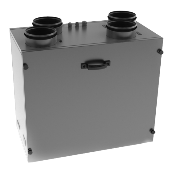
- Page 1 USER’S MANUAL Heat recovery air handling unit VUT 300 E2V EC VUT 300-2 E2V EC...
-
Page 2: Table Of Contents
VUT 300 E2V EC CONTENTS Safety requirements ................. Introduction ....................Purpose ......................Delivery set ....................Designation key ..................Technical data ..................... Unit design and operating principle ..........Mounting and set-up ................Condensate drainage ................Connection to power mains ..............Unit control .................... -
Page 3: Safety Requirements
SAFETY REQUIREMENTS • Read the user’s manual carefully prior to the operation and installation of the heat recovery air handling unit (hereinafter referred to as «the unit»). • Fulfil the user’s manual requirements as well as the provisions of all the applicable local and national construction, electrical and technical norms and standards. - Page 4 VUT 300 E2V EC UNIT OPERATION SAFETY PRECAUTIONS Do not touch the unit wash controls with wet hands. unit with water. Do not carry out the unit Protect the unit electric maintenance with parts from water ingress. hands. Use the unit only as intended by the manufacturer.
-
Page 5: Introduction
INTRODUCTION This user’s manual includes technical description, operation, installation and mounting guidelines, technical data for the VENTS VUT 300 E2VEC heat recovery air handling unit, hereinafter referred as «the unit». PURPOSE The unit is designed to ensure continuous mechanical air exchange in houses, offices, hotels, cafés, conference halls, and other utility and public spaces as well as to recover the heat energy contained in the air extracted from the premises to warm up the filtered stream of supply air. -
Page 6: Designation Key
VUT 300 E2V EC DESIGNATION KEY VUT 300-X Motor type electronically commutated Spigot orientation V - vertical Number of heaters Electric heater Spigot diameter [mm] _ – 150 2 – 160 Air capacity [m Unit type VUT - ventilation with heat recovery TECHNICAL DATA The unit is designed for indoor application with the ambient temperature ranging from +1 °C up to... - Page 7 Fig. 1. Overall and connecting dimensions Reference dimensions Model Ø D VUT 300 E2V EC VUT 300-2 E2V EC...
- Page 8 VUT 300 E2V EC Table 1. Unit technical data Model VUT 300 E2V EC VUT 300-2 E2V EC Unit voltage [V/50(60) Hz] 1 ~ 230 Maximum fan power [W] Fan current [A] Electric heater power [kW] 2 item x 2 Electric heater current [A] 2 item x 8.7...
-
Page 9: Unit Design And Operating Principle
DESIGN AND OPERATING PRINCIPLE The unit operation is as follows: Warm extract air from the room flows into the unit and is cleaned in the extract filter. Then the air is moved through the heat exchanger and is exhausted outside with the extract fan. Cold fresh air from outside flows into the unit, where it is cleaned in the supply filter. -
Page 10: Mounting And Set-Up
VUT 300 E2V EC MOUNTING AND SET-UP The units are designed for wall mounting. While installing the unit ensure convenient access for subsequent maintenance and repair. The mounting surface must be smooth. Mounting of the unit to an uneven surface can lead to the unit casing distortion and operation disturbance. - Page 11 The wall-mounted control panel is installed as follows: Carefully release the latches with a flat screwdriver by inserting it into the access holes in the lower part of the wall control panel (Fig. 4). Remove the service covers. Disconnect the cable from the terminal block. Route the cable in the wall to the speed switch installation site.
-
Page 12: Condensate Drainage
VUT 300 E2V EC CONDENSATE DRAINAGE min 3° DRAIN PIPES min 3° min 3° min 3° DRAIN HOSES U-TRAPS SEWAGE SYSTEM Fig. 6. Condensate drainage The condensate drip pan installed in the heat recovery section is provided with drain pipes. - Page 13 NEVER REMOVE THE PLUG FROM THE POWER RECEPTACLE WITH WET HANDS OR BY HOLDING ONTO THE ELECTRIC CABLE. DISCONNECT THE UNIT FROM POWER MAINS PRIOR TO ANY OPERATIONS! THE RATED ELECTRICAL PARAMETERS OF THE UNIT ARE SHOWN ON THE RATING PLATE. ANY TAMPERING WITH THE INTERNAL CONNECTIONS IS PROHIBITED AND WILL VOID THE WARRANTY.
-
Page 14: Unit Control
VUT 300 E2V EC The damper actuator must be connected to terminals X3:5, X3:6 and X3:7 of terminal block X3. A second damper can be connected to the same contacts. Additional contacts are connected according to the connection diagram (see Fig. 8). The wires run into the unit through the cable gland in the cover. - Page 15 When the unit is off (Fig. 10) the control panel display indicates: Room temperature Day of the week Time Off mode indication indicators glow in the Heater Cooling mode. Synchronously the heater cooling countdown is displayed in min: sec. Fig. 10. 0 - deactivation of the unit When the unit is on (Fig.
- Page 16 VUT 300 E2V EC UPON DEACTIVATION OF THE UNIT WITH THE ELECTRIC HEATER ENABLED THE UNIT CONTINUES TO OPERATE FOR ANOTHER 2 MINUTES TO COOL DOWN THE HEATER. THE SYMBOL IS DISPLAYED DURING THE HEATER COOLDOWN. 4. Timer. The timer is designed to switch the fans to maximum speed with subsequent automatic reset to a previous speed after a set time period, from 20 to -60 minutes.
- Page 17 To adjust the supply fan capacity press and hold and then press to set the fan speed up to set it down. Each pressing of increases or reduces the supply fan speed by 1 %. If is pressed the display indicators show the current supply fan speed (Fig.
- Page 18 VUT 300 E2V EC Press to view the controller board model code and software version code on the control panel display. To exit the Sensor Adjustment mode press Fig. 15. Software version 7. Filter replacement indication. After 3,000 machine hours the unit control panel screen changes from the operating temperature display to filter cleaning or change indication (Fig.
- Page 19 9. Scheduled Operation mode. Press and hold , then press on the control panel to activate the Scheduled Operation mode. The indicator lights up when the Scheduled Operation mode is activated. Press and hold , then press on the control panel to deactivate the Scheduled Operation mode.
- Page 20 VUT 300 E2V EC Table 3. Programming example Entry number of the week Start Heater Start Heater Start Heater Start Heater Mode Mode Mode Mode time status time status time status time status medium first medium first 07:00 08:00 17:00...
-
Page 21: Technical Maintenance
TECHNICAL MAINTENANCE Maintenance operations of the unit are required 3–4 times per year. Maintenance includes general cleaning of the unit and the following operations: 1. Filter maintenance (3–4 times per year). Clogged filters increase air resistance in the system and reduce supply air volume. The filters require cleaning not less than 3–4 times per year. - Page 22 VUT 300 E2V EC Fig. 19. Heat exchanger and filter maintenance.
- Page 23 Fig. 20. Control unit maintenance.
-
Page 24: Troubleshooting
VUT 300 E2V EC TROUBLESHOOTING Possible faults and troubleshooting Problem Possible reasons Elimination method Make sure that the unit is properly The fan(s) No power supply. connected to the electric mains and make do(es) not start any corrections, if necessary. -
Page 25: Manufacturer's Warranty
MANUFACTURER’S WARRANTY The manufacturer hereby warrants normal operation of the unit over the period of 24 months from the retail sale date provided observance of the transportation, storage, installation and operation regulations. Should any malfunctions occur in the course of the unit operation through the Manufacturer’s fault during the guaranteed period of operation the user is entitled to elimination of faults by the manufacturer by means of warranty repair at the factory carried out free of charge. -
Page 26: Acceptance Certificate
VUT 300 E2V EC FOLLOWING THE REGULATIONS STIPULATED HEREIN WILL ENSURE A LONG AND TROUBLE-FREE OPERATION OF THE UNIT. USERS’ CLAIMS SHALL BE REVIEWED ONLY UPON PRESENTATION OF THE UNIT, THE PAYMENT DOCUMENT AND THE USER’S MANUAL WITH THE SALE DATE STAMP. -
Page 27: Connection Certificate
CONNECTION CERTIFICATE VUT 300 ___ E2V EC air handling unit with heat recovery has been installed and connected to the electric mains in accordance with the requirements of this User’s Manual. Company Name Address Phone Number Installation technician's full Installation name Company Stamp Installation Date:... - Page 28 V79EN-05...
Need help?
Do you have a question about the VUT 300 E2V EC and is the answer not in the manual?
Questions and answers