Table of Contents
Advertisement
Available languages
Available languages
Quick Links
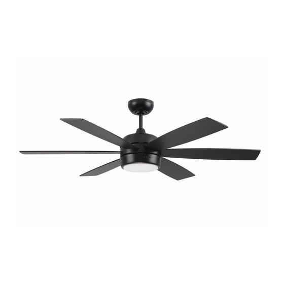
Trevor
Installation Guide
For Model:
TRV52
APPROVED FOR USE IN
DAMP LOCATIONS
net weight of fan: 17.2 lb (7.8 kg)
READ THESE INSTRUCTIONS AND
AND SAVE THEM FOR FUTURE USE
Table of Contents:
Safety Tips. pg. 3
Unpacking Your Fan. pg. 4
Parts Inventory. pg. 4
Installation Preparation. pg. 5
Hanging Bracket Installation. pg. 5
Fan Assembly. pgs. 6 - 7
Wiring. pgs. 7 - 8
Canopy Assembly. pg. 8
Blade Assembly. pg. 9
Light Kit Assembly. pgs. 9 - 10
pgs. 10 - 11
Remote/Wall Control Operation. pg. 12
Smart Ceiling Fan Wi-Fi Control. pgs. 12 - 13
Testing Your Fan. pg. 13
Troubleshooting. pg. 14
Warranty. pg. 14
Parts Replacement. pg. 14
page 1
PRINTED IN CHINA
Advertisement
Chapters
Table of Contents

Related Manuals for Craftmade Trevor


Summary of Contents for Craftmade Trevor
-
Page 1: Table Of Contents
READ THESE INSTRUCTIONS AND AND SAVE THEM FOR FUTURE USE Trevor Installation Guide Table of Contents: For Model: Safety Tips. pg. 3 TRV52 Unpacking Your Fan. pg. 4 Parts Inventory. pg. 4 Installation Preparation. pg. 5 Hanging Bracket Installation. pg. 5 Fan Assembly. - Page 2 Activating Your New Smart Fan; Downloading the Bond Home App • Using your smart device, navigate to the application store (Apple App store or Google Play), download the free Bond Home app and create account. • Ensure the fan and receiver are receiving power from the house supply using the remote control to turn the fan and light ON and OFF.
-
Page 3: Safety Tips
(2) this LED light kit must accept any interference received, including interference that may cause undesired operation. Distributed by: Craftmade, 650 S. Royal Lane, Coppell, TX, 75019; 1-800-486-4892 NOTE: The important safety precautions and instructions appearing in the manual are not meant to cover all possible conditions and situations that may occur. -
Page 4: Unpacking Your Fan
1. Unpacking Your Fan. Carefully open the packaging. Remove items from Styrofoam inserts. Remove motor housing and place on carpet or Styrofoam to avoid damage to finish. Do not discard fan carton or Styrofoam inserts should this fan need to be returned for repairs. -
Page 5: Installation Preparation
3. Installation Preparation. blade edge inches To prevent personal injury and damage, ensure (76 cm) 7 feet that the hanging location allows the blades a (2.13 m) clearance of 7 feet (2.13m) from the floor and 30in. (76cm) from any wall or obstruction. 12ft. -
Page 6: Fan Assembly. Pgs
stop pin set screw 5. Fan Assembly. Remove hanging ball from downrod provided by hanging ball loosening set screw on hanging ball. Remove pin and clip. Lower hanging ball and remove stop pin. Then slide hanging ball off downrod. [Refer to diagram 1.] clip diagram 1 Loosen yoke set screws and nut at top of motor... -
Page 7: Wiring. Pgs
5. Fan Assembly. (cont.) wood ceiling joist With the hanging bracket secured to the outlet box and able to support the fan, you are now ready to hang safety cable loop your fan. Grab the fan firmly with two hands. Slide downrod through opening in hanging bracket and let hanging ball rest on the hanging bracket. -
Page 8: Canopy Assembly
6. Wiring. (cont.) Modifications not approved by the party responsible for compliance [PLEASE NOTE: Wall and/or handheld could void the user's authority to operate the equipment. remote control must be used for fan to *NOTE: This equipment has been tested and found to comply with the limits for a Class B digital device, pursuant to Part 15 of the FCC Rules. -
Page 9: Blade Assembly
8. Blade Assembly. WARNING: To reduce the risk of serious bodily motor housing injury, DO NOT use power tools to assemble the blades. If screws are overtightened, blades may blade crack and break. Time Saver: Washers for blade screws can be set on each blade attachment screw prior to installing blades. -
Page 10: Assembly Of Handheld Remote Control
9. Light Kit Assembly. (cont.) motor housing If you wish to USE the light kit, align grooves on shade with nodules on inside of fitter plate and push up gently on shade. Turn shade to the RIGHT (clockwise) until shade fitter plate locks into place. -
Page 11: Automated Learning Process./Activating Code
10. Assembly of Handheld Remote Control. (cont.) Attach black faceplate to front of wall control; press down firmly. [Refer to diagram 3.] post post hole Align holes in wall control with posts located on hole inside of TOP part of remote control cover and press together firmly. -
Page 12: Remote/Wall Control Operation
12. Remote/Wall Control Operation. ON/OFF slider switch - turns wall control ON or OFF (switch not functional on handheld remote) HIGH button - turns fan to HIGH speed MED button - turns fan to MEDIUM speed LOW button - turns fan to LOW speed wall control OFF button handheld... -
Page 13: Testing Your Fan
13. Smart Ceiling Fan Wi-Fi Control. (cont.) (Optional) 10. Specific information about your fan: -Select “Location” and choose from one of the predefined entries or add your own by selecting “OTHER”. When finished, select “Save”. - Select device name and enter the name for your device. When finished, select “OK” to save. PLEASE NOTE: This name will be used for integrations so a simple, easy-to-remember name is best. -
Page 14: Troubleshooting
Service at 1-800-486-4892 to arrange for return of fan. 2. Check to be sure wall control (optional use) is wired Return fan, shipping prepaid, to Craftmade. We will repair properly. or ship you a replacement fan, and we will pay the return 3. - Page 15 LEER ESTAS INSTRUCCIONES Y GUARDARLAS PARA UTILIZACIÓN FUTURA Trevor Guía de instalación Índice de materias: Para modelo: Sugerencias de seguridad. Pág. 3 TRV52 Desempaquetado del ventilador. Pág. 4 Inventario de piezas. Pág. 4 Preparación para la instalación. Pág. 5 Instalación del soporte de montaje. Pág. 5 Ensamblaje del ventilador.
- Page 16 Activar su nuevo ventilador inteligente; Descargar la aplicación Bond Home • Con su dispositivo inteligente, navegar en la tienda de aplicaciones (Apple App store o Google Play), descargar la aplicación gratis Bond Home y crear una cuenta. • Asegurarse de que el ventilador y el receptor estén recibiendo la corriente del suministro de fuerza eléctrica de la casa usando el control remoto para ENCENDER y APAGAR el ventilador y la luz.
-
Page 17: Sugerencias De Seguridad. Pág
(2) este juego de luz LED tiene que aceptar cualquier interferencia recibida, inclusive interferencia que puede producir un funcionamiento indeseado. Distribuido por: Craftmade, 650 South Royal Lane, Coppell, TX 75019; 1-800-486-4892 NOTA: No se debe concluir que las precauciones de seguridad importantes e instrucciones en este manual van a abarcar todas las condiciones y situaciones posibles que puedan ocurrir. -
Page 18: Desempaquetado Del Ventilador. Pág
1. Desempaquetado del ventilador. Abrir el empaque cuidadosamente. Sacar los artículos del embalaje. Sacar el motor y ponerlo en una alfombra o en el embalaje para evitar rayar el acabado. Guardar la caja de cartón o el empaquetamiento original en caso de que tenga que mandar el ventilador para alguna reparación. -
Page 19: Preparación Para La Instalación. Pág
borde 3. Preparación para la instalación. del aspa 76 cm Para prevenir daño corporal y otros daños, estar seguro de que el lugar en donde va a colgar el ventilador le 2,13 m pulg.) permite un espacio libre de 2,13 m (7 pies) entre las (7 pies) puntas de las aspas y el piso y 76 cm (30 pulg.) entre las aspas y cualquier pared u otra obstrucción. -
Page 20: Ensamblaje Del Ventilador. Págs
perno de tope 5. Ensamblaje del ventilador. tornillo de fijación Quitar la bola que sirve para colgar del tubo provisto bola que sirve aflojando el tornillo de fijación de la bola que sirve para colgar para colgar. Quitar el perno y la clavija. Bajar la bola que sirve para colgar y sacar el perno de tope. -
Page 21: Instalación Eléctrica. Págs
5. Ensamblaje del ventilador. (cont.) viga de madera bucle del cable Ya que esté sujetado el soporte de montaje a la caja de salida y de seguridad capaz de apoyar el ventilador, usted está listo para colgar el ventilador. Agarrar el ventilador firmemente con las dos manos. Deslizar el tubo por la abertura del soporte de montaje y dejar que se detenga la bola en el soporte de montaje. -
Page 22: Colocación De La Cubierta Decorativa. Pág
6. Instalación eléctrica. (cont.) Las modificaciones no aprobadas por la parte responsable de la conformidad podrían invalidar la autorización del usuario para manejar el equipo. [FAVOR DE DARSE CUENTA: Hay que utilizar el *NOTA: Se han hecho pruebas en este equipo y se ha comprobado que cumple con los límites para control de pared y/o el control remoto de mano un aparato digital de clase B, de acuerdo con la Parte 15 de las Reglas de la FCC. -
Page 23: Colocación De Las Aspas. Pág
8. Colocación de las aspas. ADVERTENCIA: Para reducir el riesgo de lesiones corporales graves, NO utilizar herramientas eléctricas bastidor del motor para ensamblar las aspas. Si aprieta demasiado los tornillos, las aspas podrían agrietarse y quebrarse. aspa Para ahorrar tiempo: Se pueden colocar las arandelas en los tornillos que son para fijar las aspas antes de instalar las aspas. -
Page 24: Ensamblaje Del Control Remoto De Mano
9. Instalación del juego de luz. (cont.) bastidor Si desea UTILIZAR el juego de luz, alinear las del motor ranuras en la pantalla con los nódulos dentro de la placa de conexión y empujar la pantalla delicadamente hacia arriba. Girar la pantalla placa de hacia la DERECHA (en sentido de las agujas conexión... -
Page 25: Proceso De Aprendizaje Automático./ El Activar El Código. Pág
10. Ensamblaje del control remoto de mano. (cont.) poste agujero para agujero Fijar la tapa negra a la parte delantera del control de pared; el poste apretar la tapa fijamente. [Referirse al diagrama 3.] Alinear los agujeros en el control de pared con los postes que se encuentran adentro de la parte SUPERIOR de la cubierta del control remoto y apretar fijamente. -
Page 26: Funcionamiento Del Control Remoto
12. Funcionamiento del control remoto/control de pared. Interruptor deslizante - ENCIENDE y APAGA el control de pared ON/OFF (el interruptor no funciona en el control de mano) Botón HIGH - pone el ventilador en velocidad ALTA Botón MED - pone el ventilador en velocidad MEDIA Botón LOW - pone el ventilador en velocidad BAJA Botón OFF... -
Page 27: Verificación Del Funcionamiento Del
13. Control Wi-Fi para ventilador de techo inteligente. (cont.) (opcional) 9. Seleccionar "YES, IT WORKS" (sí, funciona). 10. Información específica sobre su ventilador: -Seleccionar “Location” (ubicación) y eligir una de las opciones predefinidas o agregar la suya propia seleccionando “OTHER” (otro). Cuando termine, seleccionar "Save" (guardar). - Seleccionar el nombre del aparato y registrar un nombre para dicho aparato. - Page 28 6. Asegurarse de que se conectaron bien los enchufes macho y y Craftmade pagará los gastos de envío de regreso. hembra del juego de luz LED. GARANTÍA LIMITADA DE 6 AÑOS hasta DE POR VIDA: CRAFTMADE reparará...
Need help?
Do you have a question about the Trevor and is the answer not in the manual?
Questions and answers