Table of Contents
Advertisement
Available languages
Available languages
Quick Links
Download this manual
See also:
Installation Manual
BETTER BY DESIGN
P.O. Box 1037
650 S. Royal Lane, Suite 100
Coppell, TX 75019
(800) 486-4892
8:00 to 5:00 CST (Central Standard Time)
Toll Free Fax: (877) 304-1728
email: customerservice@craftmade.com
www.craftmade.com
MEJOR DISEÑO
P. O. Box 1037
650 S. Royal Lane, Suite 100
Coppell, TX 75019 EE.UU.
(800) 486- 4892
8:00 a 5:00 CST (Hora local central)
Número de fax sin cargo: (877) 304-1728
Correo electrónico: customerservice@craftmade.com
www. craftmade.com
UNE CONCEPTION EXCEPTIONNELLE
P. O. Box 1037
650 S. Royal Lane, Suite 100
Coppell, TX 75019 EE.UU.
de 8 heures à 17 heures (Heure standard du centre)
Numéro de télécopieur gratuit : (877) 304-1728
Email: customerservice@craftmade.com
www. craftmade.com
®
®
®
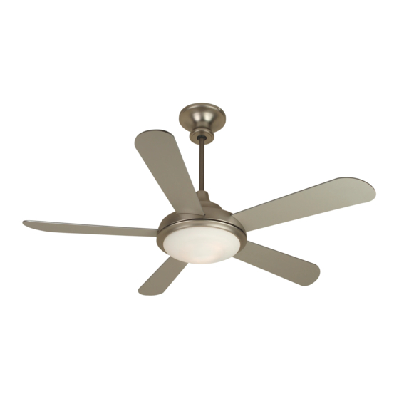
The Triumph Fan
TR52
Installation Instructions
Models: TR52
Combination Standard
Downrod and Flushmount
Assembly
®
BETTER BY DESIGN
Advertisement
Table of Contents

Related Manuals for Craftmade TR52


Summary of Contents for Craftmade TR52
-
Page 1: Installation Instructions
650 S. Royal Lane, Suite 100 Coppell, TX 75019 EE.UU. (800) 486- 4892 8:00 a 5:00 CST (Hora local central) Installation Instructions Número de fax sin cargo: (877) 304-1728 Models: TR52 Correo electrónico: customerservice@craftmade.com www. craftmade.com Combination Standard Downrod and Flushmount Assembly ®... -
Page 2: Before Assembly
Read and Save These Safety Precautions What You Have Turn off electricity at main switch before wiring or servicing fan in order to avoid possible electrical shock. Parts All wiring must be in accordance with the National Electric Code (ANSI/NFPA 70- 1999) and local electrical codes. - Page 3 A. Downrod Mount Control Unit 1 2 3 4 B. Angle Mount Downrod Installation (Normal Ceilings) Craftmade Part #45AD (see dealer) C. Flushmount IMPORTANT: If using the angle mount Battery method, check to make sure the ceiling Terminal angle is not steeper than 35º. Angles greater than 35º...
-
Page 4: Helpful Hint
Step 2 - Blade Assembly Step 1 - Downrod Option Take out the four screws in the Top Motor Housing (#4). Save the Prior to securing Mounting Bracket/Plate, screw "J" Hook (S8) into screws. Raise the Top Motor Housing (#4) off the base (see figure 1). Ceiling Outlet Box as a secondary support means. - Page 5 Step 3 - Standard Down Rod Assembly (Steps 3-7) Step 4 Locate Downrod Assembly (#2). Loosen Ball Screw on black Hanging Position Downrod so the hole in the Downrod aligns with the hole in Ball to free lock pin. Black Hanging Ball will slide down. Remove the Flange Coupling on the Motor.
-
Page 6: Step 5 - Safety Cable
Step 6 - Connecting Wires Step 5 - Safety Cable 1. Connect fan wires to ceiling wires: white fan wire to white outlet wire, For added security, attach Safety Cable from fan unit to "J" Hook (S8) in black to black and green to green. Wire Connectors (S6) are provided for outlet box. -
Page 7: Step 1 - Flushmount Option
Step 2 - Blade Assembly Step 1 - Flushmount Option Take out the four screws in the Top Motor Housing (#4). Save the Prior to securing Mounting Bracket/Plate, screw "J" Hook (S8) into screws. Raise the Top Motor Housing (#4) off the base (see figure 1). Ceiling Outlet Box as a secondary support means. -
Page 8: Step 3 - Flushmount Installation
Step 3 - Flushmount Installation Step 4 - Attaching Hanging Cable Secure the Hanging Wire by looping it through the Safety Bolt (S7)as shown in Figure 1and tightening it with the Safety For added security, attach Hanging Cable from fan unit to "Mounting Plate "J"... - Page 9 Step 6 - Attaching Safety Cable Step 5 - Connecting the Wiring 1. Connect fan wires to ceiling wires: white fan wire to white outlet wire For added security, attach Safety Cable from fan unit to "J" Hook (S8) black to black and green to green. Wire connectors (S6) are provided for in outlet box.
-
Page 10: Installing Glass
Step 7 - Electrical Connections Attaching Canopy Ceiling Connect black fan wires to black outlet wire. Connect white fan wire to Screws Attach Canopy (#3) to the Mounting (S2) white outlet wire and green grounding lead wire from the grounding Plate by aligning Canopy slots to conductor to the supply circuit (see figure A). -
Page 11: Instructions D'installation
Instructions d’installation del ensamblaje del ventilador. 2. Compruebe que el soporte de montaje esté instalado correctamente. Modèle : TR52 3. Compruebe que la unidad de luz y el vidrio estén correctamente instalados y apretados. 4. Si se usa el control de pared, revise que no sea del tipo transformador o Installation Instructions de velocidad variable. -
Page 12: Avant L'assemblage
Veuillez lire et conserver ces consignes de sécurité Composants inclus 1. Pour éviter de vous électrocuter, débranchez l'alimentation électrique au niveau de l'interrupteur principal avant de procéder au câblage ou à l'entretien du ventilateur. 2. Tout le câblage doit être effectué en accord avec le code électrique national américain Pièces Quantité... - Page 13 1 2 3 4 Montage à l’aide d’une tige de suspension suspension B. Montage sur une surface inclinée Pièce Craftmade n∞ 45AD (consultez votre revendeur) C. Le montage au plafond IMPORTANT: si vous utilisez la méthode Borne de la pile de montage inclinée, vérifiez que l'angle du...
-
Page 14: Vue Supérieure
Étape 2 - Ensemble des Pales Étape 1 - Option de downrod Retirez les quatre (4) vis sur le haut du boîtier du moteur (nº 4). Avant de fixer le support de montage/la plaque, vissez le crochet en «J» Conservez ces vis. Soulevez le haut du boîtier du moteur (nº 4) de la (S8) sur la boîte de sortie du plafond, pour qu’il serve de dispositif de base (voir la figure 1). - Page 15 Étape 4 Étape 3 Montage sur tige de suspension Placez la tige de suspension de manière à ce que son trou soit aligné avec standard et au plafond Étape 3-7 celui de l’attelage du moteur. Insérez le boulon de sécurité (S7) dans l’attelage et la tige de suspension et fixez l'écrou.
- Page 16 Étape 5 - Câble de sûreté Étape 6 - Reliez les fils Pour plus de sécurité, attachez le câble de sécurité du ventilateur au 1. Connectez les fils du ventilateur à ceux du plafond : le fil de ventilateur crochet en « J » (S8) accroché dans la boîte de sortie. Fixez l'installation blanc au fil de sortie blanc, le fil noir au fil noir et le fil vert au fil vert.
- Page 17 Étape 2 - Ensemble des Pales Step 1 - Option de flushmount Retirez les quatre (4) vis sur le haut du boîtier du moteur (nº 4). Avant de fixer le support Bracket/Plate, crochet de la vis "J" (S8) dans la Conservez ces vis.
- Page 18 Étape 4 - Attachez le câble de sécurité Étape 3 - Installation de flushmount Placer le capuchon décoratif (n° 4) sur le boîtier du moteur. Placer la coupelle (n° 3) sur le capuchon. Fixer la coupelle (n° 3) au boîtier du moteur Pour la sécurité...
- Page 19 Étape 6 - Attachez le câble de sûreté Étape 5 - Reliez le câblage Pour la sécurité supplémentaire, attachez le câble de sûreté à partir de l'unité de 1. Connectez les fils du ventilateur à ceux du plafond : le fil Pour plus de sécurité, attachez le câble de sécurité...
-
Page 20: Connexions Électriques
Connexions électriques Étape 7 - Attachez la verrière Plafond Raccordez les fils noirs du ventilateur à celui de la boîte de sortie, puis le Attachez la verrière (# 3) au plat de (S2) fil blanc du ventilateur à celui de la boîte de sortie et le fil vert du support en alignant des fentes de conducteur de mise à... -
Page 21: Instructions D'utilisation
Problèmes fréquents Instructions d’utilisation Problème A : Le ventilateur ne démarre pas Solution : 1. Vérifiez les fusibles ou le disjoncteur et remplacez-les si besoin est. ON/OFF Pour arrêt d’urgence 2. Coupez l'alimentation électrique et vérifiez tous les connecteurs. 3. Vérifiez les interrupteurs on/off ainsi que l'interrupteur de commande mural. -
Page 22: Operation Instructions
3. Check on/off TCS and wall control selector switch. See operation instructions. Instrucciones de instalación Problem B: Fan is Excessively Noisy Modelos: TR52 Remedies: 1. Check that all screws in fan assembly are tight and properly seated. 2. Check to make sure mounting bracket is installed properly. -
Page 23: Antes Del Montaje
Lea y conserve estas precauciones de seguridad Componentes Incluidos 1. Apague la electricidad con el interruptor principal antes de cablear o dar servicio al ventilador para evitar posibles choques eléctricos. Piezas Cantidad 2. Todo el cableado eléctrico debe acatar los códigos eléctricos nacionales (ANSI/NFPA 70-1999) y los códigos eléctricos locales. - Page 24 Paso B Determine el método de montaje a usar. A. Montaje con vara hacia abajo 1 2 3 4 B. Montaje angular Pieza Craftmade 45AD Instalación con vara hacia abajo (cielos rasos normales) (consulte al distribuidor) C. La montura a ras IMPORTANTE: Si utiliza el método de...
- Page 25 Paso 2 Paso 1 - Opción del downrod Saque los cuatro tornillos que se encuentran en la parte superior de Antes de sujetar el soporte de montaje / placa, atornille el gancho “J” la caja del motor (#4). Póngalos a un lado. Luego, levante la caja (S8) en la caja de salida del techo como medio de soporte secundario.
- Page 26 Paso 4 Paso 3 - Abajo y montura a ras estándar (Pasos 3-7) Sitúe la vara hacia abajo de manera que el agujero en la misma Ubique el ensamblaje de la vara hacia abajo (2). Suelte el tornillo quede alineado con el agujero en el acoplamiento del motor. Inserte de la bola negra colgante para liberar el pasador de bloqueo.
- Page 27 Paso 5 - Cable de seguridad Paso 6 - Alambres que conectan Para mayor seguridad, instale un lazo de alambre de acero desde el 1. Conecte los cables del ventilador a los del techo: el cable blanco del ventilador al gancho “J” (S7) en la caja de salida. Sujételo pasando la ventilador con el cable blanco de salida, negro con negro y verde con amarra (S8) por el cable de seguridad y el gancho “J”.
- Page 28 Paso 2 Paso 1 - Opción de Flushmount Saque los cuatro tornillos que se encuentran en la parte superior de Antes de sujetar el soporte de montaje / placa, atornille el gancho “J” la caja del motor (#4). Póngalos a un lado. Luego, levante la caja (S8) en la caja de salida del techo como medio de soporte secundario.
- Page 29 Paso 4 - Atadura del cable que cuelga Paso 3 - Instalación del flushmount Para mayor seguridad, instale un lazo de alambre de acero desde el ventilador Asegure el alambre que cuelga colocándolo a través del perno de seguridad (S7)as al gancho “J”...
- Page 30 Paso 6 - Atadura del cable de seguridad Paso 5 - Conectar el cableado 1. Conecte los cables del ventilador a los del techo: el cable blanco del ventilador Para la seguridad agregada, una el cable de seguridad de la unidad del con el cable blanco de salida, negro con negro y verde con verde.
-
Page 31: Conexiones Eléctricas
Paso 7 - Conexiones eléctricas Atadura de la cúpula Ceilo raso Conecte los cables negros del ventilador al cable negro de salida. Tornillos Conecte el cable blanco del ventilador al cable blanco de salida y al Una la cúpula (# 3) a la placa de (S2) cable conductor a tierra verde desde el conductor a tierra al circuito montaje alineando ranuras de la...
Need help?
Do you have a question about the TR52 and is the answer not in the manual?
Questions and answers