Table of Contents
Advertisement
Quick Links
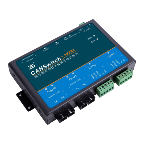
CANSwitch-AF2S2 User Manual
High-Performance Dual-CAN to Fiber Optic Switch
User Manual
UM01010101 V1.03
Date: 2019/03/26
Product User Manual
Category
Contents
Keywords
Dual CAN, dual optical, hardware switch, converter, hub
CANSwitch-AF2S2 is a high-performance dual-channel
CAN-to-fiber switch based on ZLG Electronics'
Description
advanced CAN bus technologies and operating system
technologies. It has two conversion modes: Hub and
Converter.
©2021 Guangzhou ZLG Electronics Technology Co.,Ltd.
Advertisement
Table of Contents

Related Manuals for ZLG CANSwitch-AF2S2


Summary of Contents for ZLG CANSwitch-AF2S2
- Page 1 Product User Manual Category Contents Keywords Dual CAN, dual optical, hardware switch, converter, hub CANSwitch-AF2S2 is a high-performance dual-channel CAN-to-fiber switch based on ZLG Electronics' Description advanced CAN bus technologies and operating system technologies. It has two conversion modes: Hub and Converter.
- Page 2 Changed the company name and sales network information Updated the document header and footer and "Sales and Service V1.02 March 14, 2019 Network" content and added the "Disclaimer" content V1.03 March 26, 2019 Updated product images ©2021 Guangzhou ZLG Electronics Technology Co.,Ltd.
-
Page 3: Table Of Contents
4.2.5 Modify the local IP address ................ 25 4.3 TCP Server mode ....................25 4.3.1 System block diagram ................25 4.3.2 Configuring the CANSwitch-AF2S2 device..........27 4.3.3 TCP&UDP software operation ..............27 4.3.4 CANTest software operation ..............30 ©2021 Guangzhou ZLG Electronics Technology Co.,Ltd. - Page 4 4.3.5 Test Result ....................31 4.4 TCP Client mode ....................34 4.4.1 System block diagram ................34 4.4.2 Configuring the CANSwitch-AF2S2 device..........36 4.4.3 TCP&UDP software operation ..............36 4.4.4 CANTest software operation ..............38 4.4.5 Test Result ....................40 4.5 UDP mode ......................
-
Page 5: Functions
EMC characteristics, and there is no safety problem caused by inductive coupling in the cable. CANSwitch-AF2S2 is an industrial grade product and works in the temperature range of -40℃ to +85℃. It has two optical fiber interfaces, and the highest baud rate of 2-way CAN-bus interface communication is 1 Mbps. -
Page 6: Powerful Hardware
Each CAN port opens a diagnostic port, and the host computer can obtain the error status of the corresponding CAN port by connecting this port; You can use the Windows platform configuration software to configure operating parameters. The parameters can be imported and exported; ©2021 Guangzhou ZLG Electronics Technology Co.,Ltd. -
Page 7: Product Specification
1.2 Product Specifications 1.2.1 Fiber Interfaces Number of fiber ports: 2; Interface type: SC; Fiber type: single mode; Operating wavelength: 1,310 nm; Operating rate: 100 Mbps. 1.2.2 CAN Interfaces ©2021 Guangzhou ZLG Electronics Technology Co.,Ltd. -
Page 8: Power Interface
Unless otherwise specified, the parameters listed in Table 1.1 refer to the values at Tamb=25° C. Table 1.1 Electrical parameters Parameter Name Symbol Rating Unit Power voltage +9~36V Power consumption 3350 ℃ Operating ambient temperature Tamb -40℃~85℃ ℃ Storage temperature Tstg -40℃~85℃ ©2021 Guangzhou ZLG Electronics Technology Co.,Ltd. -
Page 9: Mechanical Dimensions
High-Performance Dual-CAN to Fiber Switch User Manual User Manual 1.3 Mechanical Dimensions To install CANSwitch-AF2S2, see the appearance and mechanical dimensions (unit: mm) provided in Figure 1.3. The figure specifies the length, width, height, and part of the mechanical structure of the product. -
Page 10: Product Hardware Interface Description
High-Performance Dual-CAN to Fiber Switch User Manual User Manual 2. Hardware Interfaces This chapter describes the hardware interfaces of CANSwitch-AF2S2. 2.1 Appearance Drawing Figure 2.1 shows the front appearance of the product. Figure 2.2 and Figure 2.3 show the side appearance. -
Page 11: Power Interface
User Manual 2.2 Power Interfaces CANSwitch-AF2S2 uses a 9-36 V DC power supply that is easily available at the industrial site, and is equipped with two wiring ports. One is a round hole socket and the other is a terminal block. Both interfaces support positive and negative connections, with no need to confirm the positive and negative poles. -
Page 12: Fiber Interface
Figure 2.7 Optical fiber interface and indicators 2.6 CAN Port The CANSwitch-AF2S2 device has two CAN ports. Figure 2.8 shows its appearance. It has two indicators: CAN0 and CAN1. When a device is connected, when there is data communication; Table 2.1 describes the pin definition. -
Page 13: Led Indicator
CANSwitch-AF2S2 High-Performance Dual-CAN to Fiber Switch User Manual User Manual 2.7 LED Indicators The CANSwitch-AF2S2 device has six indicators, PWR, SYS, Fiber0, Fiber1, CAN0, and CAN1, as shown in Figure 2.9. Figure 2.9 Indicators Table 2.2 describes the indicators. Table 2.2 Description of LED indicators... -
Page 14: Quick Use In Hub Mode (Hub Mode)
Turn the switch to Hub and press the reset button. After the device beeps twice, it enters Hub mode. For details, see Section 2.4. The CANSwitch-AF2S2 supports using the serial port to configure the device, as shown in Figure 3.1. The device can be configured as long as the dedicated RS232 configuration port is connected to the PC. -
Page 15: Configure The Device
Search devices. The CANSwitch supports searching by serial port. When searching by serial port, the COM port should be selected correctly. See Figure 3.3. Figure 3.3 Searching for devices Note: For details about how to configure the device, see 错误!未找到引用源。. ©2021 Guangzhou ZLG Electronics Technology Co.,Ltd. - Page 16 CAN device connected to the CAN1 port. The data of CAN1 port can only be forwarded to CAN0 port of device 2 and CAN1 port of device 2 Figure 3.4 Configuration of the first CANSwitch ©2021 Guangzhou ZLG Electronics Technology Co.,Ltd.
- Page 17 The baud rate should be 500K, which should be consistent with the CAN device connected to the CAN1 port. The data of CAN1 port can only be forwarded to all CAN buses Figure 3.5 Configuration of the second CANSwitch ©2021 Guangzhou ZLG Electronics Technology Co.,Ltd.
-
Page 18: Cantest Software Operation
3.4 CANTest Software Operation We need a device equipped with a CAN port to demonstrate how the CANSwitch-AF2S2 device realizes bidirectional transparent conversion of CAN network data and optical fiber data. Here, select the USBCAN interface card, which is convenient... - Page 19 User Manual to use. Its related information is available at http://www.zlg.cn. Note: For details about how to use the CANTest software, see ZLG Electronics CAN Test Software and Interface Function User Manual. First, connect the CANSwitch-AF2S2 device to the PC by using an optical cable, and connect the CANSwitch-AF2S2 device to the USBCAN interface card by using a twisted pair cable (CANH is connected, and CANL is connected.
-
Page 20: Test Result
On the tab page of any CANtest software, click the "Send" button. You can then receive the data you just sent on the tab page of another CANtest software. 3.5 Test Result Open all six CAN cards, as shown in Figure 3.11. ©2021 Guangzhou ZLG Electronics Technology Co.,Ltd. - Page 21 The first CAN bus sends data, the second, fifth, and sixth CAN buses receive data, and the third and fourth CAN buses do not receive data, which conforms to the configuration of the first CANSwitch-AF2S2. See Figure 3.12. Figure 3.12 First CAN bus sending data...
- Page 22 Figure 3.13 Second CAN bus sending data The third and fourth CAN buses send data, and all other CAN buses can receive data, which conforms with the configuration of the second CANSwitch-AF2S2. See Figure 3.14. Figure 3.14 Third and fourth CAN buses sending data...
- Page 23 CANSwitch-AF2S2 High-Performance Dual-CAN to Fiber Switch User Manual User Manual Figure 3.15 Fifth and sixth CAN buses sending data ©2021 Guangzhou ZLG Electronics Technology Co.,Ltd.
-
Page 24: Quick Use In Converter Mode (Converter Mode)
The ZNetCom software is the configuration software of CANSwitch-AF2S2 device running on Windows. No matter what the current IP address of the CANSwitch-AF2S2 device is, you can obtain the current IP address of the CANSwitch-AF2S2 device by using ZNetCom software and configure it. The procedure for obtaining CANSwitch-AF2S2 device IP address using ZnetCom software is as follows: Connect the hardware. -
Page 25: Pc And Device Network Segment Detection
4.2.3 PC and Device Network Segment Detection Before using the PC to communicate with the CANSwitch-AF2S2 device, make sure that your PC and the CANSwitch-AF2S2 device are on the same network segment. The CANE device is set with a default IP address (192.168.0.178) and network mask (255.255.255.0) when it leaves the factory. -
Page 26: Add The Ip Address Of The Machine (Use The Windows7 Operating System As An Example)
Figure 4.4 Checking whether the IP address of the CANSwitch-AF2S2 device and the PC are on the same network segment The following describes how to set your PC and CANSwitch-AF2S2 device to the same network segment. If you are using Windows 2000/XP/7/8/10, there are two methods. One is to add the local IP address, and the other is to change the local IP address. - Page 27 Select "Internet Protocol Version 4 (TCP/Ipv4)" and click "Properties", as shown in Figure 4.6. Figure 4.6 Local area connection properties 2 The "General" page displays the current IP address, subnet mask and default gateway and other information. Click "Advanced", as shown in Figure 4.7. ©2021 Guangzhou ZLG Electronics Technology Co.,Ltd.
- Page 28 Click the "Add" button, as shown in Figure 4.8. Figure 4.8 TCP/IP settings Enter the IP address and subnet mask in this window. The IP address should be on the same network segment as CANSwitch-AF2S2, as shown in Figure 4.9. ©2021 Guangzhou ZLG Electronics Technology Co.,Ltd.
-
Page 29: Modify The Local Ip Address
4.3 TCP Server Mode 4.3.1 System Block Diagram In TCP Server mode, CANSwitch-AF2S2 will not actively connect with other devices. It always waits for the connection of the client (TCP Client), and can perform two-way data communication after establishing a TCP connection with the client. Figure 4.11 shows the communication establishment process. - Page 30 High-Performance Dual-CAN to Fiber Switch User Manual User Manual Figure 4.11 Communication in TCP Sever mode Tip: In this mode, the client connects to the CANSwitch-AF2S2 device over the "working port (see Table 5.2)" corresponding to the CAN port. ©2021 Guangzhou ZLG Electronics Technology Co.,Ltd.
-
Page 31: Configuring The Canswitch-Af2S2 Device
CANSwitch-AF2S2 High-Performance Dual-CAN to Fiber Switch User Manual User Manual 4.3.2 Configuring the CANSwitch-AF2S2 Device Figure 4.12 shows the configuration in TCP Server mode. Be sure to submit the configuration modifications The default password is 88888 The IP address configuration should be... - Page 32 Select TCP mode in Type, enter the IP address and the working port number of CANSwitch-AF2S2, and click Create. See Figure 4.15. Figure 4.15 Creating a connection Click Connect to connect the CANSwitch-AF2S2 device. See Figure 4.16. ©2021 Guangzhou ZLG Electronics Technology Co.,Ltd.
- Page 33 High-Performance Dual-CAN to Fiber Switch User Manual User Manual Figure 4.16 Opening a connection When the triangle below the client mode turns green, the connection is successful. See Figure 4.17. Figure 4.17 Connection created ©2021 Guangzhou ZLG Electronics Technology Co.,Ltd.
-
Page 34: Cantest Software Operation
Choose the correct device. Select USBCAN-E-U here, as shown in Figure 4.19. Figure 4.19 Selecting a device Select the correct baud rate, click OK, and start the CAN, as shown in Figure 4.20. Figure 4.20 Starting the device ©2021 Guangzhou ZLG Electronics Technology Co.,Ltd. -
Page 35: Test Result
After starting the device properly, the page appear, as shown in Figure 4.21. Figure 4.21 Starting the device For details about how to use the CANTest software, see the ZLG Electronics CAN Test Software and Interface Function User Manual. 4.3.5 Test Result Send a CAN frame whose ID is 00000000 and data is 0001020304050607 by using the CANTest software over USBCAN. - Page 36 Figure 4.23 PC receiving data 1 The CAN frame with ID 00000009 and data 0001020304050607 is sent, and the ID is within the receiving range. The peer device can receive data correctly, as shown in Figure 4.24. ©2021 Guangzhou ZLG Electronics Technology Co.,Ltd.
- Page 37 The device has received the data, as shown in Figure 4.25. For the format of the received data, see Appendix A. Figure 4.25 PC receiving data 2 Use the TCP&UDP test tool to send CAN frames, as shown in Figure 4.25. For the data format, see Appendix A. ©2021 Guangzhou ZLG Electronics Technology Co.,Ltd.
-
Page 38: Tcp Client Mode
USBCAN can be received properly as shown in Figure 4.27. Figure 4.27 USBCAN receiving data 1 4.4 TCP Client Mode 4.4.1 System Block Diagram In TCP Client mode, the CANSwitch-AF2S2 will actively connect to the preset TCP ©2021 Guangzhou ZLG Electronics Technology Co.,Ltd. - Page 39 There are six groups of valid "Destination Port" and "Destination IP". The device will connect to the TCP server specified by the six groups of parameters in turn based on the preset number of connections until the connection is successful. ©2021 Guangzhou ZLG Electronics Technology Co.,Ltd.
-
Page 40: Configuring The Canswitch-Af2S2 Device
CANSwitch-AF2S2 High-Performance Dual-CAN to Fiber Switch User Manual User Manual 4.4.2 Configuring the CANSwitch-AF2S2 Device Figure 4.29 shows the configuration in TCP CLIENT mode. Be sure to submit the configuration modifications The default password is 88888 The IP address configuration should be... - Page 41 Figure 4.31 Creating a connection Click Start Server to start the service. See Figure 4.32. Figure 4.32 Opening a connection When the triangle under the server mode turns green, the server is created successfully. See Figure 4.33. ©2021 Guangzhou ZLG Electronics Technology Co.,Ltd.
-
Page 42: Cantest Software Operation
4.4.4 CANTest Software Operation Double-click the CANTest software icon to run the software, as shown in Figure 4.34. Figure 4.34 CANTest software Choose the correct device. Select USBCAN-E-U here, as shown in Figure 4.35. ©2021 Guangzhou ZLG Electronics Technology Co.,Ltd. - Page 43 Figure 4.35 Selecting a device Select a baud rate, click OK, and start the CAN, as shown in Figure 4.36. Figure 4.36 Opening the device After the device starts properly, a page appears, as shown in Figure 4.37. ©2021 Guangzhou ZLG Electronics Technology Co.,Ltd.
-
Page 44: Test Result
High-Performance Dual-CAN to Fiber Switch User Manual User Manual Figure 4.37 Device started For details about how to use the CANTest software, see the ZLG Electronics CAN Test Software and Interface Function User Manual. 4.4.5 Test Result Send a CAN frame whose ID is 00000000 and data is 0001020304050607 by using the CANTest software over USBCAN. - Page 45 The CAN frame with ID 00000011 and data 0001020304050607 is sent, and the ID is within the receiving range. The peer device can receive data correctly, as shown in Figure 4.40. Figure 4.40 USBCAN sending data 2 ©2021 Guangzhou ZLG Electronics Technology Co.,Ltd.
- Page 46 Because the preset frame ID filter only filters the frame ID sent from the CAN port to the optical fiber, and the frame ID sent from the optical fiber to the CAN port is not filtered, ©2021 Guangzhou ZLG Electronics Technology Co.,Ltd.
-
Page 47: Udp Mode
UDP working method is not error prone. The devices working in this mode are equal, and there is no server and client. Figure 4.44 shows the communication process. Figure 4.44 UDP mode communication ©2021 Guangzhou ZLG Electronics Technology Co.,Ltd. - Page 48 Tip: In this mode, the CANSwitch-AF2S2 uses "working port (see Table 5.2)" to receive UDP packets sent by user equipment; the data received by the CAN port of the CANSwitch-AF2S2 device will be sent to the "destination port (see Table 5.2)" of six groups of valid "destination IP (see Table 5.2)".
-
Page 49: Configuring The Canswitch-Af2S2 Device
CANSwitch-AF2S2 High-Performance Dual-CAN to Fiber Switch User Manual User Manual 4.5.2 Configuring the CANSwitch-AF2S2 Device Figure 4.45 shows the configuration in UDP mode. Be sure to submit the configuration modifications The default password is 88888 The IP address configuration should be... - Page 50 Figure 4.47 Opening the TCP&UDP test tool Select UDP mode in Type, enter the IP address and the working port number of CANSwitch-AF2S2, and local port, and click Create. See Figure 4.48. Figure 4.48 Creating a connection Click Connect to connect the CANSwitch-AF2S2 device. See Figure 4.49.
-
Page 51: Cantest Software Operation
When the triangle below the client mode turns green, the connection is successful. See Figure 4.50. Figure 4.50 Connection created 4.5.4 CANTest Software Operation Double-click the CANTest software icon to run the software, as shown in Figure 4.51. ©2021 Guangzhou ZLG Electronics Technology Co.,Ltd. - Page 52 Select the correct baud rate, click OK, and start the CAN, as shown in Figure 4.53. Figure 4.53 Opening the device After the device starts properly, a page appears, as shown in Figure 4.54. ©2021 Guangzhou ZLG Electronics Technology Co.,Ltd.
-
Page 53: Test Result
High-Performance Dual-CAN to Fiber Switch User Manual User Manual Figure 4.54 Device started For details about how to use the CANTest software, see the ZLG Electronics CAN Test Software and Interface Function User Manual. 4.5.5 Test Result Send a CAN frame whose ID is 00000000 and data is 0001020304050607 by using the CANTest software over USBCAN, as shown in Figure 4.55. - Page 54 Figure 4.57. Figure 4.57 USBCAN sending data 2 The device has received the data, as shown in Figure 4.58. For the format of the received data, see Appendix A. ©2021 Guangzhou ZLG Electronics Technology Co.,Ltd.
- Page 55 Use the TCP&UDP test tool to send CAN frames, as shown in Figure 4.59. For the data format, see Appendix A. Figure 4.59 PC sending data 1 Since there is no preset frame ID filtering, both frames of data USBCAN can be received properly, as shown in Figure 4.60. ©2021 Guangzhou ZLG Electronics Technology Co.,Ltd.
- Page 56 CANSwitch-AF2S2 High-Performance Dual-CAN to Fiber Switch User Manual User Manual Figure 4.60 USBCAN receiving data 1 ©2021 Guangzhou ZLG Electronics Technology Co.,Ltd.
-
Page 57: Znetcom Software Configuration
5. ZNetCom Software Configuration The ZNetCom software is dedicated configuration software for CANSwitch-AF2S2 device running on Windows. You can obtain the IP address of the CANSwitch-AF2S2 device, view and change the device configuration parameters, and upgrade the device firmware by using the ZNetCom software. - Page 58 5.4 appears, select Yes. Figure 5.4 Installing the runtime library After the installation is complete, the window for successful installation as shown in Figure 5.5 will appear. Click [Finish] to exit the installation software. ©2021 Guangzhou ZLG Electronics Technology Co.,Ltd.
-
Page 59: Obtaining Device Configurations
5.2 Obtaining Device Configurations Before obtaining the configuration information, check whether the RS232 configuration serial port has been connected to the computer or the CANSwitch-AF2S2 device and the PC network card have been connected with a network cable (a fiber-to-Ethernet switch needs to be added).. - Page 60 Click in the toolbar. A dialog box appears for communication link selection. The CANSwitch-AF2S2 allows you to configure the device over optical fiber or serial ports . Which method you choose depends on how you connect the device to the PC. If you use the LAN port to connect to the PC, choose optical fiber;...
- Page 61 ZNetCom software, as shown in Figure 5.9. Device list Figure 5.9 Obtaining CANSwitch-AF2S2 device configuration properties Double-click the device item in the device list; or after selecting the device item, click in the toolbar or in the property bar. The "Get Device Information" dialog box appears, as shown in Figure 5.10.
- Page 62 Figure 5.10 Obtaining configuration data When the "Get Device Information" dialog box disappears, you can view the CANSwitch-AF2S2 device configurations as shown in Figure 5.11 and Figure 5.12 in the property column. Figure 5.11 CANSwitch-AF2S2 device configuration hub (Hub) mode...
- Page 63 CANSwitch-AF2S2 High-Performance Dual-CAN to Fiber Switch User Manual User Manual Figure 5.12 CANSwitch-AF2S2 device configuration information converter (Converter) mode ©2021 Guangzhou ZLG Electronics Technology Co.,Ltd.
-
Page 64: Modify Device Configurations
User Manual 5.3 Modifying Device Configurations When you modify the CANSwitch-AF2S2 device configurations by using the ZNetCom software, the device configuration password (the default value is "88888") is required. After you modify the device configurations in the property column, enter the device configuration password in the current password, click to complete the device configuration modification. -
Page 65: Configuration Parameter Description
High-Performance Dual-CAN to Fiber Switch User Manual User Manual 5.4 Configuration Parameter Description 5.4.1 Configuration in Hub Mode (Hub Mode) Table 5.1 describes the default settings of the CANSwitch-AF2S2 device in hub mode. Table 5.1 Description of "Property column" items in hub mode Category... - Page 66 ID set by the user Lower limit of the together determine the range of the 00(HEX) standard frame standard frame ID to be received. ©2021 Guangzhou ZLG Electronics Technology Co.,Ltd.
-
Page 67: Configuration Instructions In Converter Mode (Converter Mode)
A to Z, 0 to 9. Modifying this value is very CANSwitch-AF2S2 name useful users identify multiple CANSwitch-AF2S2 devices on the same network. Before changing other items, you must enter Current the correct password. The password contains a “88888” password... - Page 68 Device IP 192.168.0.178 by a network device (such as a PC and address CANSwitch-AF2S2). It is unique on the same network. address The subnet mask is very important to the informati network. Within the same network, the IP address and subnet mask are the same value.
- Page 69 Static acquisition means that you directly informati enters the "IP address", "Subnet mask", and "Gateway". Dynamic acquisition means that operation the CANSwitch-AF2S2 module uses the DHCP How to get an Static acquisition protocol to obtain the IP address, subnet mask IP address...
- Page 70 UDP. When TCP is used, a connection is established before data can be transferred. TCP Sever mode is to wait for client connection; 2. TCP Client is the CANSwitch-AF2S2 device actively connecting to the destination IP and port. Among the two CANSwitch-AF2S2s, one How TCP...
- Page 71 Listen only: The CAN port works in listening CAN working mode and does not respond; Normal mode Self-test: port works self-transmitting and self-receiving mode. This is used to check whether if it can properly and whether it is damaged. ©2021 Guangzhou ZLG Electronics Technology Co.,Ltd.
- Page 72 (unit: ms), and the number of packet interval (ms) frames has not been reached, all data frames that have been received and have not been sent will be encapsulated into an optical fiber packet and sent to the network port. ©2021 Guangzhou ZLG Electronics Technology Co.,Ltd.
- Page 73 1FFFFFFF(HEX) limit values of the received extended frame ID frame set by the user together determine the range of the extended frame ID to be received. Lower limit of the extended 00(HEX) frame ©2021 Guangzhou ZLG Electronics Technology Co.,Ltd.
- Page 74 When the CANSwitch-AF2S2 works in TCP Sever, each CAN port can have a maximum of 200 TCP connections by default without configuration;...
- Page 75 CANSwitch-AF2S2 device. Only the network data sent through this Destination port can be received by the CANSwitch-AF2S2 8001/8002 port 1 device, and the data frame received by the CAN port of the CANSwitch-AF2S2 device will also be sent to this port through the optical fiber.
- Page 76 Except for the working port, destination port and destination IP address, the default parameter values of CAN1 are exactly the same; the meaning of each parameter is the same as that of each parameter of CAN0. ©2021 Guangzhou ZLG Electronics Technology Co.,Ltd.
-
Page 77: Save Restored Settings
User Manual 5.5 Saving Restored Settings To help you modify the configurations of the CANSwitch-AF2S2 device in batches, the ZNetCom software allows you to import/export configurations. The Import/Export function button is located on the property column, as shown in Figure 5.14. -
Page 78: Upgrade Firmware
CANSwitch-AF2S2 series devices support local firmware upgrade. When you upgrade the CANSwitch-AF2S2 device by using the ZNetCom software, the PC and the CANSwitch-AF2S2 device must be on the same network segment (refer to 4.2 PC and device network segment detection ). The firmware upgrade procedure is as follows: In the device list column of ZNetCom software, select the device to be upgraded in the list item, and right-click the mouse. - Page 79 Click . The device starts firmware upgrade, as shown in Figure 5.19. Figure 5.19 Firmware upgrade in progress After about 1 minute, the firmware can be upgraded, as shown in Figure 5.20. Wait about 30 seconds until the system is initialized and starts. ©2021 Guangzhou ZLG Electronics Technology Co.,Ltd.
- Page 80 High-Performance Dual-CAN to Fiber Switch User Manual User Manual Figure 5.20 Firmware upgraded If the upgrade fails due to an accident (such as power failure and network cable disconnection), power on the device, and perform search and upgrade again. ©2021 Guangzhou ZLG Electronics Technology Co.,Ltd.
-
Page 81: Disclaimer
ZLG Electronics does not guarantee the applicability of this document at any time. ZLG Electronics shall reserve the right to update this manual without prior notice. To get the latest version, please visit the official website of ZLG Electronics regularly or contact ZLG Electronics. Thank you! - Page 82 CAN帧 … CAN帧 1个CAN帧包含13个字节 帧信息:长度1个字节,用于标识该CAN帧的一些信息,如类型、长度等 Bit7 Bit0 保留 保留 FF: 标准帧和扩展帧的标识,1为扩展帧,0为标准帧。 RTR: 远程帧和数据帧的标识,1为远程帧,0为数据帧。 保留值为0,不可写入1。 D3~D0 :标识该CAN帧的数据长度。 帧ID:长度4个字节,标准帧有效位是11位,扩展帧有效位是29位。 高字节 低字节 高字节 低字节 如上为扩展帧ID号 如上为标帧ID号 0x12345678的表示方式 0x3FF的表示方式 帧数据:长度8个字节,有效长度由帧信息的D3~D0的值决定。 DATA1 DATA8 如上为8个字节有效数据 的表示方式 DATA1 DATA8 如上为6个字节有效数据 的表示方式 ©2021 Guangzhou ZLG Electronics Technology Co.,Ltd.
- Page 83 Even with a baud rate of 1,000 kbps, the CAN cannot send it so fast. Therefore, it is recommended that you should not send more than 400 UDP frames per second, and should not convert more than 4000 frames per second into CAN frames. ©2021 Guangzhou ZLG Electronics Technology Co.,Ltd.
- Page 84 附录B Data conversion format of TCP notification port in CAN port state 某路CAN对应的TCP通知端口被连接后,如果此路CAN发生错误, 通知端口将向主机定时发出状态警告,TCP包数据段格式如下: CMD Time1 Time2 Time3 Time4 55h 固定格式。包头AAh 00h,包尾55h 状态码 Time1 Time2 Time3 Time4 错误计数(32bit),高字节在前,即Time1为高字节 Status description (all are CANSwitch-AF2S2 devices) Time error count Notification value value period (seconds) Fiber send buffer about to overflow Fiber send buffer overflowed 0.5s...
- Page 85 CANSwitch-AF2S2 High-Performance Dual-CAN to Fiber Switch User Manual User Manual occurrences CAN controller bus error (as long as there is an error) Number of occurrences Other errors Number of occurrences ©2021 Guangzhou ZLG Electronics Technology Co.,Ltd.
- Page 86 CANSwitch-AF2S2 High-Performance Dual-CAN to Fiber Switch User Manual User Manual Dreams come true with professionalism and dedication. Guangzhou ZLG more details, Welcome call please visit national service hotline Electronics Co., Ltd. www.zlg.cn 400-888-4005 ©2021 Guangzhou ZLG Electronics Technology Co.,Ltd.
Need help?
Do you have a question about the CANSwitch-AF2S2 and is the answer not in the manual?
Questions and answers