Advertisement
Quick Links
Item
Subject
184.1
Electronic
Systems
Motorcycle Unlocking
184.2
Final Drive Belt
184.3
Front Fork Reflector
184.4
Front Fork Reflector
184.5
Clutch Cable Guide
184.6
Big End Bearing Selection Chart
184.7
Detent Wheel and Detent Lever Spring
184.8
Triumph Diagnostic Tool Compatibility with
Windows Operating Systems
184.9
Rider Foot Pegs
184.10
Factory
Activated
Technical Bulletin 182, December 2017)
Technical Bulletin 184 Issue 1
Technical Bulletin 184
02.2018
Contents
Model Affected
Commissioning
and
Batteries
(replaces
Tiger 1200 XRX, Tiger 1200 XRX-LRH, Tiger 1200
XRT, Tiger 1200 XCX, Tiger 1200 XCA
Thunderbird, Thunderbird - ABS, Thunderbird SE,
Thunderbird Commander, Thunderbird LT, Thunder-
bird Storm and Thunderbird Night Storm
Bonneville T100, Bonneville T100 Black, Bonneville
T120, Bonneville T120 Black, Bonneville Bobber, Street
Cup, Street Scrambler, Street Twin and Thruxton
1200
Thruxton 1200R
Bonneville Bobber
Street Triple S From VIN 803572, Street Triple R
From VIN 806646, Street Triple R (LRH) From VIN
822626 and Street Triple RS From VIN 800262
Speed Triple S, Speed Triple R, Tiger Sport
Not Applicable
Bonneville Bobber and Bonneville Bobber Black
Tiger 1200 XR, Tiger 1200 XRX, Tiger 1200 XRX-LRH,
Tiger 1200 XRT, Tiger 1200 XCX, Tiger 1200 XCA, Ti-
ger 800 XR, Tiger 800 XRX, Tiger 800 XRX-LRH, Ti-
ger 800 XRT, Tiger 800 XCX, Tiger 800 XCA
1 of 24
Advertisement

Related Manuals for Triumph 184.1


Summary of Contents for Triumph 184.1
- Page 1 822626 and Street Triple RS From VIN 800262 184.7 Detent Wheel and Detent Lever Spring Speed Triple S, Speed Triple R, Tiger Sport 184.8 Triumph Diagnostic Tool Compatibility with Not Applicable Windows Operating Systems 184.9 Rider Foot Pegs Bonneville Bobber and Bonneville Bobber Black 184.10...
-
Page 2: Initial Steps
Ensure that the motorcycle battery is fully charged and installed as described in the service manual. Download and install the latest version of the Triumph Diagnostic Tool Software to your computer as described in the Triumph Diagnostic Tool Installation Guide. - Page 3 To check the smart key is in active mode, press the smart key button and ensure the LED flashes green. If the LED flashes red, press and hold the button until the LED changes to green. Remove the rider’s seat. Connect the Triumph Diagnostic tool. US markets Only: Turn the master ignition switch to the ON position. ckde...
- Page 4 Core Activity Warning Always use Automatic Model Selection when downloading calibrations. Manual model selection must only be used when attempting to restart an interrupted or failed download, or if an incorrect model is detected by Automatic Model Selection. Always ensure that the correct model is detected or selected before selecting a calibration for download and never attempt to download calibrations listed for an incorrect model.
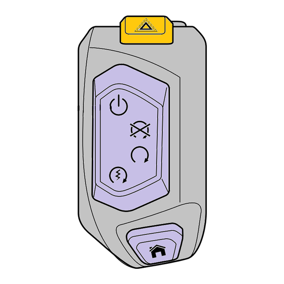
- Page 5 Press the Power ON/OFF button to turn the ignition OFF. Click Next, the download will begin. ckdp_2 Power ON/OFF button Note: • The calibration download has two stages. When the first download stage has completed, the diagnostic tool will prompt you to present a paired key to the LF antenna and press the Power ON/OFF button to start the second download stage.
- Page 6 Smart keys should be positioned so that the side with the logo/button is facing away from the LF antenna. Key (smart key shown) LF antenna Hold the key against the LF antenna until the Triumph diagnostic tool reports the key has been successfully paired. Note: •...
- Page 7 Switch the engine stop switch to the RUN (ON) position. ckdp_1 Engine stop switch RUN (ON) position Download the latest calibration as normal, using automatic model detection. Unlock the Engine ECM Unlock the engine ECM as described in the Triumph Diagnostic Tool User Guide. Technical Bulletin 184 Issue 1 7 of 24...
- Page 8 Final Steps • Check and erase all stored Chassis ECM, Engine ECM and ABS DTC’s. • Disconnect the Triumph Diagnostic Tool. • Refit the rider’s seat. • Check that the motorcycle can be powered ON and started using each key.
- Page 9 Item: 184.2 Description: Final Drive Belt Model Affected: Thunderbird, Thunderbird - ABS, Thunderbird SE, Thunderbird Commander, Thunderbird LT, Thunderbird Storm and Thunderbird Night Storm The inspection of the final drive belt for the above models is as described in the Service Manual with the addition of the following instruction.
- Page 10 Item: 184.3 Description: Front Fork Reflector Model Affected: Bonneville T100, Bonneville T100 Black, Bonneville T120, Bonneville T120 Black, Bonneville Bobber, Street Cup, Street Scrambler, Street Twin and Thruxton 1200 The installation instructions for the front fork reflector for the above models will be added to the relevant Service Manuals at their next update.
- Page 11 Item: 184.4 Description: Front Fork Reflector Model Affected: Thruxton 1200R The installation instructions for the front fork reflector for the above models will be added to the relevant Service Manuals at their next update. Note: • When fitting a new reflector to the front fork, it must be fitted 105 mm from the lower edge of the lower yoke.
- Page 12 A new clutch cable guide and clutch cable rubbing strip has been introduced to the above models from VIN 863367. For models up to VIN 863366, Triumph recommends that if the clutch cable requires replacing the cable guide on the left hand fork is to be replaced also. To facilitate this a parts kit (part number T2021648) is...
- Page 13 Clutch Cable Removal From the left hand side of the headstock, remove the harness guide and discard the fixings and the harness guide. L0169 Clutch cable Fixings Harness guide Remove the clutch cable, as described in the Service Manual. Release the clutch cable guide fixing and remove the cable guide from the left hand fork. Discard the cable guide and fixing.
- Page 14 Position the clutch cable guide to its clamp a shown in the following illustration. Secure with the M5 x 10 mm fixing but do not fully tighten at this stage. ckfu Cable guide Fixing With the steering in the straight ahead position, the clutch cable guide is to be positioned 33° from the centre line of the fork and the top edge of the clutch cable guide clamp 70 mm from the lower edge of the upper yoke.
- Page 15 Fit the rubbing strip to the clutch cable and ensure it is central in the cable guide. L0576 Rubbing strip Clutch cable guide (headlight removed for clarity) Continue fitting the clutch cable as described in the Service Manual. On the left hand side of the headstock, fit the new harness guide and tighten the new M5 x 12 mm fixings to 1.5 Nm.
- Page 16 Item: 184.6 Description: Big End Bearing Selection Chart Model Affected: Street Triple S From VIN 803572, Street Triple R From VIN 806646, Street Triple R (LRH) From VIN 822626 and Street Triple RS From VIN 800262 The dimensions given in the big end bearing selection chart in the workshop manual are incorrect. The correct information is displayed in the following table: Big End Bearing Selection Chart Shell Colour...
- Page 17 Item: 184.7 Description: Detent Wheel and Detent Lever Spring Model Affected: Speed Triple S, Speed Triple R, Tiger Sport A new detent wheel and detent lever spring has been introduced to the Tiger Sport from the engine numbers detailed below: New Parts Introduced In Production Model From Engine Number...
- Page 18 184.8 Description: Triumph Diagnostic Tool Compatibility with Windows Operating Systems Model Affected: Not Applicable From April 2018, the Triumph Diagnostic Tool will no longer operate on computers running Microsoft ® ® Windows XP or Vista Users still using these operating systems should upgrade their operating systems, and if necessary their hardware, before April 2018.
- Page 19 Item: 184.9 Description: Rider Foot Pegs Model Affected: Bonneville Bobber and Bonneville Bobber Black The removal and installation of the rider left and right hand foot rests have not been covered in the Bonneville Bobber and Bonneville Bobber Service Manuals. For the removal and installation of the rider foot pegs follow procedure described below.
-
Page 20: Installation
Note: • Note the position of the foot peg spring for installation. Remove the E-clip, clevis pin, foot peg and spring from its mounting. ckek E-clip Clevis pin Foot peg Spring Left Hand Foot Peg Remove and discard the shouldered bolt securing the gear change pedal to the left hand control plate. Detach the gear change pedal from the control plate. - Page 21 Remove the E-clip, clevis pin, foot peg and spring from its mounting. ckek E-clip Clevis pin Foot peg Spring Fit the right hand side control plate to the frame and tighten the fixings to 24 Nm. L0162 Right hand control plate Fixings Left Hand Foot Peg Fit the spring to the foot peg as noted for removal.
- Page 22 Position the foot peg to the left hand control plate, fit the clevis pin and secure with the E-clip. Fit the gear change pedal to the control plate and tighten the new shouldered bolt to 22 Nm. ckgh Shouldered bolt Gear change pedal E-clip Clevis pin...
- Page 23 If the battery voltage is 11.0 Volts or lower at any point, take a photograph clearly showing the battery, battery VIN label and multimeter reading, then contact Triumph service. Record any actions advised by Triumph service on the YTZ Factory Activated Battery Condition Log Sheet.
- Page 24 First Check Within seven days of receipt of the motorcycle: • Remove the battery from the motorcycle packing crate. • Remove and discard the battery packaging. • Check the battery VIN label matches the motorcycle VIN. • Using a multimeter of known calibration, check the battery voltage. •...
Need help?
Do you have a question about the 184.1 and is the answer not in the manual?
Questions and answers