ADC HIGAIN HDSL2 Manual
Hide thumbs
Also See for HIGAIN HDSL2:
- Manual (81 pages) ,
- Quick installation manual (8 pages) ,
- User manual (66 pages)
Table of Contents
Advertisement
Quick Links
Advertisement
Table of Contents

Related Manuals for ADC HIGAIN HDSL2


Summary of Contents for ADC HIGAIN HDSL2
- Page 1 HDSL2 L ECHNICAL RACTICE HiGain HDSL2 MODE STATUS LINE H2TU-C-231 List 1F • DSX-1 Part Number: 150-2404-16 CLEI Code: VACHU48C LINE LIST ™152-231-116-01)¨ Section Number 152-231-116-01...
- Page 2 Contents herein are current as of the date of publication. ADC reserves the right to change the contents without prior notice. In no event shall ADC be liable for any damages resulting from loss of data, loss of use, or loss of profits, and ADC further disclaims any and all liability for indirect, incidental, special, consequential or other similar damages.
- Page 3 Unpack each container and inspect the contents for signs of damage. If the equipment has been damaged in transit, immediately report the extent of damage to the transportation company and to ADC DSL Systems, Inc. Order replacement equipment, if necessary.
- Page 4 Inspecting Shipment 152-231-116-01, Revision 01 October 2, 2000 H2TU-C-231...
-
Page 5: Table Of Contents
152-231-116-01, Revision 01 Table of Contents ABLE OF ONTENTS Overview ____________________________________________________________________________ 1 Features ..............................1 Compatibility .............................2 Applications ............................2 Front Panel __________________________________________________________________________ 3 Installation___________________________________________________________________________ 7 Verification ............................8 Verification without a Downstream Device ................8 Verification with a Downstream Device ................8 Provisioning__________________________________________________________________________ 9 Reviewing System Settings........................9 Accessing the Provisioning Screens ....................9 Connecting to a Maintenance Terminal................9... - Page 6 Table of Contents 152-231-116-01, Revision 01 Testing _____________________________________________________________________________ 46 Front-Panel System Alarms......................46 Alarm Option for Digital Loop Carrier (DLC) Feed ............47 Retiring System Alarms ....................47 Remote LOS and AIS Response ..................48 OCT55 Test Pattern with AMI Code....................48 Loopback Operation ........................
- Page 7 5. Inventory Screen............................13 6. Configuration Menu ............................14 7. Configuration Menu - Standard Options (Defaults Shown)................15 8. Configuration Menu - ADC Options (Defaults Shown)................15 9. Configuration Menu - Set Factory Defaults ....................24 10. Configuration Menu - Master Clear ......................25 11. Sectionalized Analysis of the DS1 Interface ....................27 12.
- Page 8 4. Logon Screen Menus ............................ 11 5. H2TU-C-231 List 1F Standard Config Screen Options................. 16 6. H2TU-C-231 List 1F ADC Config Screen Options ..................17 7. DS1/DSX-1 24-hour PM Threshold ......................20 8. Response to H2TU-R DS1 Frame Conversion Options ................21 9.
-
Page 9: Overview
HiGain HDSL2 products provide 1.552 Mbps transmission on one unconditioned copper pair over the full Carrier Service Area (CSA) range. The CSA includes loops up to 12,000 feet of 24 AWG wire or 9,000 feet of 26 AWG wire, including bridged taps. -
Page 10: Compatibility
Overview 152-231-116-01, Revision 01 – Loss of Signal/Alarm Indication Signal (LOS/AIS) payload alarm – Selectable loopback activation codes • Compatible with Small Cross-Section Shelf (SXSS) and equipment • Network Management and Administration (NMA) interface DS1 is used throughout this document to refer to either the remote unit’s DS1 interface or the line unit’s DSX-1 interface. -
Page 11: Front Panel
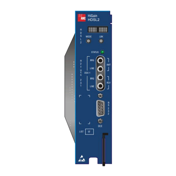
152-231-116-01, Revision 01 Front Panel RONT ANEL Figure 1 shows the H2TU-C-231 List 1F front panel. Table 1 on page 4 describes the front-panel components. For a pinout diagram of the H2TU-C card-edge connector, see Figure 33 on page 61. For a pinout diagram of the craft port, see Figure 34 on page HiGain... - Page 12 Front Panel 152-231-116-01, Revision 01 Table 1. Front-Panel Description Front-Panel Feature Function Front-panel display Displays four-character status, provisioning, and alarm system messages. The front-panel display illuminates when power is initially applied. To conserve power, the display only remains on for 5 minutes. Using the MODE or LBK buttons reactivates the display and restarts the 5-minute timer.
-
Page 13: Front-Panel Display Messages
152-231-116-01, Revision 01 Front Panel Table 2 lists the front-panel display messages. The four-character display reports the code of a pertinent alarm, loopback, or diagnostic message and, in some cases, is followed by a second four-character message that modifies the first message with a value or current configuration setting. Table 2. - Page 14 The multiplexers of the two devices on Span n are trying to establish synchronization with each other, where n is the number of the span. HiGain HDSL2 System Armed Armed to respond to Intelligent Repeater Loop (ILR) codes. BAD RT?
-
Page 15: Installation
Installation NSTALLATION Upon receipt of the equipment, inspect the contents for signs of damage. If the equipment has been damaged in transit, immediately report the extent of damage to the transportation company and to ADC. H2TU-C-231 H iG a in... -
Page 16: Verification
Installation 152-231-116-01, Revision 01 ERIFICATION Once the H2TU-C-231 is installed, verify that it is operating properly. To do this, monitor the following: • Status LED • Status messages reported by the front-panel display (Table 2 on page For information on turn-up instructions, see the Help menu and select Turn-up Aid. Verification without a Downstream Device If there is no downstream device installed: Verify that the H2TU-C powers up. -
Page 17: Provisioning
Configure the maintenance terminal to the following communication settings: • 9600 baud • No parity • 8 data bits • 1 stop bit • Hardware flow control to OFF CTRL If necessary, press to refresh the HiGain HDSL2 logon screen. H2TU-C-231 List 1F October 2, 2000... -
Page 18: Logon Screen
152-231-116-01, Revision 01 Logon Screen The HiGain maintenance terminal screens allow you to monitor, provision, and troubleshoot an HDSL2 system. To select a menu from the HiGain HDSL2 logon screen (Figure 3 on page 11), do one of the following: •... -
Page 19: Logon Screen
Help Provides a glossary of terms used in the HiGain HDSL2 maintenance screens, a list of navigational keys, aids for turn-up and printing, and ADC contact information. H2TU-C-231 List 1F... -
Page 20: Provisioning Tasks
25). Setting Date and Time Monitor Performance Event Log Config Inventory Rlogon Help +----------------------+ | Standard Options -> | ADC Options -> Date and Time -> +-------------------------------+ | Date (mm/dd/yyyy): 09/20/2000 | Time (hh:mm[:ss]): 01:36:01 +-------------------------------+ ID: xxxx--xxxx--xxxx--xxxx 09/20/2000 01:36:01... -
Page 21: Setting Circuit Id Numbers
152-231-116-01, Revision 01 Provisioning Setting Circuit ID Numbers The Inventory screen provides product information on all units in the system and allows the setting of the circuit and unit identification numbers. Monitor Performance Event Log Config Inventory Rlogon Help -------------------------- Product Information ---------------------------- Unit... -
Page 22: Configuring The System
Standard and ADC configuration options. Standard options are those that are supported by HiGain units when connected to units from other vendors. ADC options are an extended set of options available only when using HiGain units exclusively. For a description of each option and a list of... -
Page 23: Configuration Menu - Standard Options (Defaults Shown)
| H2TU-R DS1 Frame Conversion (CONV) : ACON | +-----------------------------------------------+ Use <Spacebar> to cycle through option settings and <Enter> to activate. ID: xxxx--xxxx--xxxx--xxxx 09/20/2000 01:36:13 H2TU-C System: OK Figure 8. Configuration Menu - ADC Options (Defaults Shown) H2TU-C-231 List 1F October 2, 2000... -
Page 24: H2Tu-C-231 List 1F Standard Config Screen Options
0 to 15 dB Determines the minimum allowable margin below which a system alarm can occur. Zero disables the alarm. The Margin (Alarm) Threshold can only be set through the HiGain HDSL2 maintenance screens. 4 dB Default value. DS1 Frame Formatting... -
Page 25: H2Tu-C-231 List 1F Adc Config Screen Options
Configures the power output levels of the H2TU-R customer unit towards the Option” on page network to comply with the Enhanced template as defined in Section 6.1.4.2 of ANSIT1.E1.4. Table 6. H2TU-C-231 List 1F ADC Config Screen Options Screen ADC Config Screen Display... - Page 26 Provisioning 152-231-116-01, Revision 01 Table 6. H2TU-C-231 List 1F ADC Config Screen Options (Continued) Screen ADC Config Screen Display Selection Description Options Code Special Loopback SPLB GNLB Configures the HiGain system to respond to the generic inband loopback Mode codes.
- Page 27 152-231-116-01, Revision 01 Provisioning Table 6. H2TU-C-231 List 1F ADC Config Screen Options (Continued) Screen ADC Config Screen Display Selection Description Options Code H2TU-R DS1 Frame CONV Framing functionally determined by the framing option. Frame format Conversion conversion is inhibited at the H2TU-R.
- Page 28 Provisioning 152-231-116-01, Revision 01 DS1 BER (DBER) Option. The DS1 BER alarm occurs when any of the DS1 or DSX-1 performance monitoring parameters listed in Table 7 exceed the counts shown for the 24-hour period between 12:00:00 AM through 11:59:59 PM. These thresholds correspond to a 10 BER.
-
Page 29: Extended Superframe Format
152-231-116-01, Revision 01 Provisioning • FCON — This is the forced conversion setting. Table 8 on page 21 lists the HiGain responses by case number to both the ACON and FCON settings for the CONV option. The responses are identical, except for cases 3 and 4. - Page 30 Provisioning 152-231-116-01, Revision 01 Table 10. SuperFrame Format Frame Bits SF Number Terminal Framing Bit SuperFrame Signaling Bit ESF-RAI to SF-RAI Overwrite (ROVR) Option. If the ESF RAI to SF RAI Overwrite (ROVR) option is enabled, it allows a network ESF RAI or ESF RAI-CI pattern to be converted into a CPE SF RAI or SF RAI-CI pattern, and overwrites bit 2 of every DS0 channel with a zero.
- Page 31 152-231-116-01, Revision 01 Provisioning first bit is numbered bit 0, bits 3088, 3474, and 5790 are logical zeroes and all other bits in the pattern are logical ones. An alternative interpretation of the AIS-CI signature is that the AIS signal modified by the AIS-CI signature is equivalent to an ESF signal in which the FPS bits, the CRC-6 bits, and the payload are set to all ones and the DL is overwritten by the pattern 01111100 11111111.
-
Page 32: Resetting To Factory Defaults
Performance Event Log Config Inventory Rlogon Help +----------------------+ | Standard Options -> | ADC Options -> | Date and Time -> | Master Clear Set Factory Defaults +----------------------+ SETTING FACTORY DEFAULTS...SERVICE MAY BE INTERRUPTED! ARE YOU SURE (Y/N)? ID: xxxx--xxxx--xxxx--xxxx... -
Page 33: Clearing The History, Alarm, And Event Log Screens
Event Log Config Inventory Rlogon Help +----------------------+ | Standard Options -> | ADC Options -> | Date and Time -> Master Clear | Set Factory Defaults | +----------------------+ Clear ALL performance, alarm and event log entries. Are you sure (Y/N)? -
Page 34: Monitoring System Activity And Performance
Monitoring System Activity and Performance 152-231-116-01, Revision 01 ONITORING YSTEM CTIVITY AND ERFORMANCE The HDSL2 system provides the following maintenance screens for monitoring system activity and assessing performance: • The Monitor screens provide a graphical representation of circuit activity and allow initiation of loopbacks. •... -
Page 35: Performance Monitoring From The H2Tu-R
152-231-116-01, Revision 01 Monitoring System Activity and Performance H2TU-R ERFORMANCE ONITORING FROM THE If the downstream device detected is an H2TU-R List 4, in addition to the standard features of the H2TU-R, its functionality will be enhanced to produce unique Performance Monitoring (PM) and testing capabilities. Network surveillance is a key maintenance strategy. -
Page 36: Using The Monitor Screen To View System Activity
Monitoring System Activity and Performance 152-231-116-01, Revision 01 Network Elements (NEs), such as the ADA T3AS test and performance monitoring system, can be used to collect the performance monitoring data to allow full-time surveillance of the DS1 signal. By installing T3AS at a network boundary (for example, Interexchange Carrier [IEC], Point of Presence [POP], and a remote unit at the network interface), the Local Exchange Carrier (LEC) can monitor the performance of its portion of the network and rapidly sectionalize circuit problems. - Page 37 152-231-116-01, Revision 01 Monitoring System Activity and Performance Table 11. Monitor Screen Descriptions Field Description Active Loopback An active loopback is indicated on the lower third of the Monitor screen. Available loopbacks are indicated by gray text. See Table 20 on page 50 for a summary of the HiGain loopback codes.
-
Page 38: Using The Performance Screens To View Performance Data
Monitoring System Activity and Performance 152-231-116-01, Revision 01 SING THE ERFORMANCE CREENS TO ERFORMANCE To access the Performance history screens: Press to select the Performance screen. Press the SPACEBAR to select either interface (H2TU-C DS1, H2TU-R DS1, H2TU-C HDSL2, or H2TU-R HDSL2), then press ENTER Press the... - Page 39 152-231-116-01, Revision 01 Monitoring System Activity and Performance Monitor Performance Event Log Config Inventory Rlogon Help H2TU-R DS1 48 Hour History (Page 1 of 4) ----------------------------------------------------------------------------- Time CV-L ES-L SES-L UAS-L CV-P ES-P SES-P UAS-P PRM-NE PRM-FE *02:00 *03:00 *04:00 *05:00 *06:00 *07:00...
-
Page 40: H2Tu-R Ds1 Current Statistics
Monitoring System Activity and Performance 152-231-116-01, Revision 01 Examples of current statistics screens are shown below. Figure 16 Figure 17 show statistics for the DS1 interface at the remote unit and line unit, respectively. These screens report 1-day, 1-hour, and 15-minute statistics. Monitor Performance Event Log... - Page 41 152-231-116-01, Revision 01 Monitoring System Activity and Performance Table 12. Error Acronyms Used on the DS1 Performance History Screens Error Error Description Description Acronym Acronym CV-L Code Violation - Line SES-P Severely Errored Seconds - Path Seconds with SES, CRC (ESF) ≥ 320, or Total BPV count.
-
Page 42: Blockage Indicator Statistics At The H2Tu-R Ds1 Interface
Monitoring System Activity and Performance 152-231-116-01, Revision 01 Blockage Indicator Statistics at the H2TU-R DS1 Interface Figure 18 is an example of an H2TU-R Blockage Indicator (BI) History screen as viewed from the H2TU-R following a remote log on. This screen can also be viewed when logged on locally at the remote unit. The BI statistics can also be retrieved using inband or Facility Data Link access. -
Page 43: Performance History At The Hdsl2 Interface
152-231-116-01, Revision 01 Monitoring System Activity and Performance Performance History at the HDSL2 Interface The HDSL2 interface has 31-day, 48-hour, 25-hour, and current statistic screens for the H2TU-C. Figure 19 Figure 20below are examples of 31-day and 48-hour performance history screens. Figure 21 Figure 22 on page 36... -
Page 44: H2Tu-C Hdsl2 25-Hour Performance History
Monitoring System Activity and Performance 152-231-116-01, Revision 01 Monitor Performance Event Log Config Inventory Rlogon Help H2TU-C HDSL2 25 Hour History (Page 1 of 9) ------------------------------------------------------------------------------ Time LOSWS *00:45 *01:00 *01:15 *01:30 01:45 02:00 02:15 02:30 02:45 03:00 03:15 03:30 Press: (N)ext Page, (P)revious Page, C(l)ear History ------------------------------------------------------------------------------ Use <Space>... - Page 45 152-231-116-01, Revision 01 Monitoring System Activity and Performance Table 13. Error Acronyms Used on the HDSL2 Performance History Screens Error Acronym Description Code Violation Total count of HDSL2 CRC errors. Errored Seconds Seconds with HDSL2 CRC ≥ 1 or LOSW ≥ 1 Severely Errored Seconds Seconds with HDSL2 CRC ≥...
-
Page 46: Using The Performance Screens To View Alarm Data
Monitoring System Activity and Performance 152-231-116-01, Revision 01 SING THE ERFORMANCE CREENS TO LARM To access the alarm history screens: Press to select the Performance screen. Press the SPACEBAR to select an interface (H2TU-C DS1, H2TU-R DS1, H2TU-C HDSL2, or H2TU-R HDSL2), then press ENTER Press the... -
Page 47: H2Tu-R Ds1 Alarm History Screen
152-231-116-01, Revision 01 Monitoring System Activity and Performance Monitor Performance Event Log Config Inventory Rlogon Help H2TU-R DS1 Alarm History ------------------------------------------------------------------------------ Alarm First Last Status Count RLOS 09/01/2000 00:00 09/01/2000 00:45 ALARM RAIS TX RAI-CI PRM-NE DISABLED PRM-FE DISABLED DBER 09/01/2000 00:37 09/01/2000 00:45 Press: C(l)ear Alarm History... -
Page 48: Alarm History At The Hdsl2 Interface
Monitoring System Activity and Performance 152-231-116-01, Revision 01 Alarm History at the HDSL2 Interface The HDSL2 Alarm History screens report alarms at the H2TU-C and the H2TU-R. Figure 25 shows the H2TU-C HDSL2 alarm history. Table 15 describes the alarms that are reported at the H2TU-C or H2TU-R. Monitor Performance Event Log... -
Page 49: Using The System Event Log To Track Events
152-231-116-01, Revision 01 Monitoring System Activity and Performance SING THE YSTEM VENT OG TO RACK VENTS The System Event Log screen displays the 100 most recent events (most recent event displayed first) and provides the following information: • Origin tags to identify the source of a Write entry (see “Origin Tags”... -
Page 50: Origin Tags
Monitoring System Activity and Performance 152-231-116-01, Revision 01 Origin Tags The origin tags identify the source of all Write entries and how an event occurred. The exact meaning is dependent on the type of event and the unit reporting the event. A Write entry changes a system parameter or an option setting. -
Page 51: Event Log Messages
152-231-116-01, Revision 01 Monitoring System Activity and Performance Event Log Messages Table 17 lists all the possible messages that can be displayed by the System Event Log screen. Table 17. Event Log Messages DS1 Alarm History reset DS1 PM register reset HDSL2 Alarm History reset HDSL2 PM register reset Loop Down (any segment) -
Page 52: Using The Sectionalized Event Log To Isolate Trouble
Monitoring System Activity and Performance 152-231-116-01, Revision 01 SING THE ECTIONALIZED VENT OG TO SOLATE ROUBLE The Sectionalized Event Log screen (Figure 27) displays the date and time of the 100 most recent sectionalized events for all four legs of the H2TU-R DS1 interface (Figure 28 on page 45). -
Page 53: Sectionalized Events
152-231-116-01, Revision 01 Monitoring System Activity and Performance Sectionalized events isolate trouble to a particular circuit leg. For example, an ES listed under the NET-TX column indicates that an errored second condition exists on the NET-TX circuit leg beginning with the time stamp and continuing until an OK or other new event is recorded. -
Page 54: Testing
Testing 152-231-116-01, Revision 01 ESTING This section provides information about front-panel system alarms, LOS and AIS response, OCT55 test procedure, and loopback testing. RONT ANEL YSTEM LARMS Table 19 summarizes all possible system alarms in order of priority as they appear on the front panel. When multiple alarms occur, the front-panel display only reports the highest priority alarm. -
Page 55: Alarm Option For Digital Loop Carrier (Dlc) Feed
152-231-116-01, Revision 01 Testing Table 19. Front-Panel System Alarms Summary (Continued) Front-Panel Alarm Description To Inhibit Message xxx-HBER HDSL2 Block Error Rate The HDSL2 BER has exceeded the set threshold Select NONE for the HBER limits of 10 or 10 . -
Page 56: Remote Los And Ais Response
NLBP Remove alarm AIS event? pattern AIS to CPE ALMP Pass on LOS to NET ADC Option HDSL2 Standard Option NAIS Send AIS to NET Default configurations are boldface. Send AIS-CI to NET Figure 29. H2TU-R LOS and AIS Response Priorities... -
Page 57: Loopback Operation
152-231-116-01, Revision 01 Testing OOPBACK PERATION HiGain has a family of loopback options for analyzing circuit functionality. The loopback signal is transmitted and returned to the sending device for comparison. This allows you to verify the integrity of the HDSL2 channels to the H2TU-C, the H2TU-C DSX-1 interface, and the DS1 channels to the customer. -
Page 58: Generic Loopback Commands
Testing 152-231-116-01, Revision 01 ENERIC OOPBACK OMMANDS The HiGain Generic Loopback (GNLB) commands allow you to use inband codes to loop up either NLOC (4-in-7) or NREM (3-in-7) towards the network. In addition, these inband codes loop up CREM (6-in-7) or CLOC (5-in-7) towards the customer. -
Page 59: Special Loopback Commands
152-231-116-01, Revision 01 Testing PECIAL OOPBACK OMMANDS In addition to the GNLB loopback command mode, a HiGain system can be configured for special loopback command modes. These are selected by configuring the unit for the desired loopback mode (Config menu, Special Loopback Mode option) from the maintenance terminal Monitor screen. -
Page 60: Manual Loopback Session
Testing 152-231-116-01, Revision 01 ANUAL OOPBACK ESSION A manual loopback session allows you to select any one of the HiGain loopbacks listed in Table 20 on page 50 with the exception of SmartJack loopbacks, which can only be issued by inband commands. Setting the Loopback Time-Out Option Before initiating a loopback session, verify that the loopback time-out parameter is set to the desired setting. -
Page 61: Loopback Test Procedures
152-231-116-01, Revision 01 Testing You can terminate loopbacks manually and exit the MAN LPBK mode by simultaneously pressing the MODE and LBK buttons for 3 or more seconds. If no loopback is active, the MAN LPBK mode automatically terminates after 30 seconds. -
Page 62: Loopback Modes
Testing 152-231-116-01, Revision 01 Have the CO tester send the NLOC (4-in-7) inband loopup for 5 seconds. You should be able to observe the NLOC message on the front-panel display. (The Status LED on the front panel should be yellow, and the loopback mode should also be identified on the Span Status screen.) Repeat Step 2. -
Page 63: A1Lb, A2Lb, And A5Lb Test Procedures
152-231-116-01, Revision 01 Testing A1LB, A2LB, and A5LB Test Procedures Using the codes listed in Table 21, a network tester can activate NLOC or NREM loopbacks (or SMJK, if enabled). A tester at the customer premises can activate CLOC or CREM loopbacks. Following Table 21 is a step-by-step test procedure for verifying the integrity of the HDSL2 channels at every... - Page 64 Testing 152-231-116-01, Revision 01 To perform the A1LB, A2LB, and A5LB loopback test procedures: Send the inband Arming and NI LPBK code 11000 to the H2TU-C for at least 5 seconds. Monitor the output of the H2TU-C for the return of the pattern. Return of the pattern indicates one of the following: •...
-
Page 65: A3Lb And A4Lb Test Procedures
152-231-116-01, Revision 01 Testing The Armed mode has an automatic time-out of 120 minutes, but this timer is reset to 120 for any of the following events: • Loopback terminates (manually or time-out) • Query • Alternate query • Far End activate •... -
Page 66: Testing With The H2Tu-R Signal Generator
Monitor Performance Event Log Config Inventory Rlogon Help +-----------------------+ | Standard Options -> | | ADC Options -> | Signal Generator -> +--------------------------------------+ | Test Signal Generator | Test Signal Pattern : ALL 1 | Test Signal Linecode : AMI | Test Signal Direction : NET &... -
Page 67: Appendix A - Specifications
152-231-116-01, Revision 01 Appendix A - Specifications A - S PPENDIX PECIFICATIONS Power HDSL2 Span Voltage 0 or -185 Vdc CO Supply -48 Vdc nominal (-42.5 to -56.5 Vdc) (See “Power Consumption”, “Maximum Power Dissipation”, and “Maximum Current Drain” on page 60.) Electrical Protection Secondary surge and power cross-protection on HDSL2 ports. -
Page 68: Power Consumption
Appendix A - Specifications 152-231-116-01, Revision 01 OWER ONSUMPTION The three most important power parameters of an H2TU-C are its maximum power consumption, maximum power dissipation, and maximum current drain. Table 24 describes line-powered circuits on 9 kft, 26 AWG loops. Table 24. -
Page 69: Loop Attenuation
152-231-116-01, Revision 01 Appendix A - Specifications TTENUATION Each loop has no more than 35 dB of loss at 196 kHz, with driving and terminating impedances of 135 Ω (see Table 25 below). Table 25. HDSL2 Cable Attenuation Chart Ω Cable Gauge Loss at 196 kHz (dB/kft) per kft... -
Page 70: Network Management Control Bus
Appendix A - Specifications 152-231-116-01, Revision 01 The HDSL2 span is accessed on pins 26 and 27 which are assigned to Loop 2 in 4W HDSL circuits. Network Management Control Bus The H2TU-C provides a Network Management Control Bus on pin 46 of the card-edge connector. This allows the various management system protocols to manage the H2TU-C through the HMU-319 HiGain Management Unit. -
Page 71: Craft Port
152-231-116-01, Revision 01 Appendix A - Specifications RAFT Figure 34 shows the pinout for the craft port connector and its connection to a DB-9 or DB-25 connector on a maintenance terminal. Figure 34. RS-232 Craft Port Pinouts H2TU-C-231 List 1F October 2, 2000... -
Page 72: Appendix B - Functional Operation
UNCTIONAL PERATION ADC HDSL2 technology provides full-duplex services at standard DS1 rates over copper wires between an H2TU-C and an H2TU-R, which comprise one HiGain system. HiGain systems use Overlapped Pulse Amplitude Modulation Transmission with Interlocking Spectra (OPTIS) transceiver systems to establish full-duplex, 1.552 kbps data channels between the H2TU-C-231 and a remotely located H2TU-R. -
Page 73: Appendixc - Compatibility
152-231-116-01, Revision 01 Appendix C - Compatibility C - C PPENDIX OMPATIBILITY The HiGain system uses HDSL2 transmission technology as recommended by ANSI committee in compliance with the ANSI T1.418-2000 HDSL2 standards. HiGain complies with GR-63-CORE, TR-TSY-000499, and GR-1089-CORE. The H2TU-C-231 List 1F is compatible with the following DS1 repeater shelves and associated equipment: •... -
Page 74: Appendixd - Product Support
ADC Customer Service Group provides expert pre-sales and post-sales support and training for all its products. ECHNICAL UPPORT Technical support is available 24 hours a day, 7 days a week by contacting the ADC Wireline Systems Division Customer Service Engineering Group at one of the following numbers: Telephone: 800.638.0031 or 714.730.3222... - Page 75 Pack the equipment in a shipping carton. Write the ADC Wireline Systems Division address and the RMA number you received from Customer Service clearly on the outside of the carton and return to: ADC Wireline Systems Division 14352 Franklin Ave.
-
Page 76: Appendix E - Abbreviations
Appendix E - Abbreviations 152-231-116-01, Revision 01 E - A PPENDIX BBREVIATIONS Far End FPS: Framing Pattern Sequence ACO: Alarm Cutoff ACON: Auto Conversion ADSL: Asymmetrical Digital Subscriber Line HBER: HDSL2 Bit Error Rate Threshold AIS: Alarm Indication Signal HCDS: High Capacity Digital Service AIS-CI: Alarm Indication Signal-Customer Installation... - Page 77 152-231-116-01, Revision 01 Appendix E - Abbreviations PBOC: Power Back Off Customer PBON: Power Back Off Network Payload POTS: Plain Old Telephone Service PRM: Performance Report Messaging PRM-FE: Performance Report Messaging-Far End PRM-NE: Performance Report Messaging-Near End PWRF: Power Feed RAI: Remote Alarm Indication RAI-CI:...
- Page 78 Appendix E - Abbreviations 152-231-116-01, Revision 01 October 2, 2000 H2TU-C-231 List 1F...
-
Page 79: Certification And Warranty
ADC during the 90-day warranty period is, at ADC’s option, either (a) return of the price paid or (b) repair or replace of the software. ADC also warrants that, for a period of thirty (30) days from the date of purchase, the media on which software is stored will be free from material defects under normal use. - Page 80 ADC DSL Systems, Inc. 14402 Franklin Avenue Tustin, CA 92780-7013 Tel: 714.832.9922 Fax: 714.832.9924 Technical Assistance 800.638.0031 714.730.3222...
Need help?
Do you have a question about the HIGAIN HDSL2 and is the answer not in the manual?
Questions and answers