AVT MAGIC AE4 DAB/DAB+ Hardware Manual
Audio encoder
Hide thumbs
Also See for MAGIC AE4 DAB/DAB+:
- Quick manual (18 pages) ,
- Hardware manual (23 pages) ,
- Quick manual (20 pages)
Table of Contents
Advertisement
Quick Links
Advertisement
Table of Contents

Subscribe to Our Youtube Channel
Related Manuals for AVT MAGIC AE4 DAB/DAB+


Summary of Contents for AVT MAGIC AE4 DAB/DAB+
- Page 1 MAGIC AE4 DAB/DAB+ Audio Encoder Quad DAB/DAB+ Audio Encoder Hardware Manual...
- Page 2 90411 Nuernberg Germany Phone +49-911-5271-0 Telefax +49-911-5271-100 © AVT Audio Video Technologies GmbH All Rights reserved. Reproduction in whole or in parts is prohibited without the written consent of AVT GmbH. Subject to changes. Release date: July 2022 Version 2.2...
-
Page 3: Table Of Contents
INDEX Introduction ....................... 4 Conventions ....................4 Safety ......................5 General safety requirements ................5 Construction ....................6 Functionality ....................7 Putting MAGIC AE4 into operation ..............8 Mounting ......................8 Connection to the mains voltage ..............9 Operational elements at the front side ............10 Front status LEDs .................. -
Page 4: Introduction
INTRODUCTION MAGIC AE4 DAB/DAB+ Audio Encoder offers in the standard version one DAB/DAB+ hardware encoder and can be optionally upgraded to a dual, triple or quad DAB/DAB+ encoder. Each of the four channels are independent and can be configured independently as a DAB or DAB+ encoder. The audio programs can be supplied via the four digital AES/EBU stereo interfaces. -
Page 5: Safety
Safety The unit described has been designed to the latest technical parameters and complies with all current national and international safety requirements. It operates on a high level of reliability because of long-term experience in development and constant and strict quality control in our company. This manual contains basic safety instructions that must be observed during configuration and operation. -
Page 6: Construction
Construction MAGIC AE4 contains a mainboard with an additional connector, a display, a keypad and five LEDs as well as a headphone interface on the front side. The functions of the system are implemented in a 19” x 1U housing, the dimensions are 434mm x 44,5mm , 252mm. -
Page 7: Functionality
Functionality MAGIC AE4 offers in the standard version one DAB/DAB+ hardware encoder and can be optionally upgraded with three further encoders. Each of the four channels are independent and can be configured independently as a DAB or DAB+ encoder. The audio programs can be supplied via the four digital AES/EBU stereo interfaces. An analogue stereo interface is also available. -
Page 8: Putting Magic Ae4 Into Operation
PUTTING MAGIC AE4 INTO OPERATION Mounting With its dimensions (W × H × D) of 434 mm × 44,5 mm (1 U) × 252 mm the MAGIC AE4 system can either be used as desktop device or mounted into a 19-inch rack. 19“mounting brackets are included in delivery. -
Page 9: Connection To The Mains Voltage
Connection to the mains voltage Attention! High touch current possible! Before connecting the power supply, MAGIC AE4 must be earthed. For this purpose, the earthing cable must have a conductor cross-section of at least 2.5mm² if it is mechanically protected, or otherwise 4.0mm². The following graphic symbols are located on the rear of the unit to indicate the correct and safe use. -
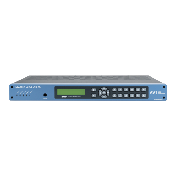
Page 10: Operational Elements At The Front Side
Operational elements at the front side The system has an illuminated graphical display with a resolution of 160 x 32 pixels and 19 operating buttons. On the right side next to the display there are two softkeys whose current functions are indicated on the display. -
Page 11: Wiring
Wiring The system offers four digital AES/EBU stereo Audio interfaces and one analogue stereo Audio interface. Eight TTL inputs/outputs and eight relays can be freely programmed, e. g. for alarming. Two network interfaces are available as standard. Analogue Analogue Module slot 1 Audio Inputs Audio Outputs (optional Dual LAN module) -
Page 12: Interfaces
INTERFACES On the front side of the unit 5 LEDs for status indication and a headphone interface for monitoring are available. The connectors for the interfaces are at the rear side. MAGIC AE4 front view MAGIC AE4 rear view MAGIC AE4 rear view with optional Dual LAN Upgrade and redundant power supply upgrade... -
Page 13: Lan 1 And Lan 2 Interfaces
LAN 1 and LAN 2 interfaces All services (Audio, PAD, SNMP, NTP, etc.) can be configured freely for both network interfaces. For the LAN interface a RJ45 socket is used. The pin assignment of the socket is shown below. Pin assignment: ETHERNET INTERFACES LAN 1 / LAN 2 Socket: RJ-45 Signal Electrical characteristics... -
Page 14: Ttl/Relay Interface
TTL/Relay interface The TTL / Relay interface is realised as a 25-pin socket. It provides 8 TTL in- puts or outputs and 8 Relay contacts. The pin assignment of the socket is shown below Table: TTL/Relay interface Signal Electrical characteristics TTL 1 input/output TTL interface:... -
Page 15: Headphone Interface
Headphone interface For Audio Monitoring a standard 6.3 mm phones interface is available at the front panel. Table: Headphone interface Signal Electrical characteristics Ground Connector (female): 6.3 mm jack Audio Left Audio Right Analogue Audio interface The unit provides an analogue Audio input and output. For the input an XLR socket and for the output an XLR plug is available. -
Page 16: Digital Audio Interfaces
Digital Audio interfaces MAGIC AE4 provides four digital AES/EBU Audio inputs and outputs available on two 15-pin Sub-D sockets. As an option adapter cables with XLR connectors can be provided. The pin assignment of the 15-pin Sub-D sockets is described below. Table: Digital Audio Interfaces AES/EBU 1-2 and AES/EBU 3-4 Socket: Sub-D 15 pin Signal... -
Page 17: Power Supply
100 – 230 V AC, 50 – 60 Hz, auto adjusting, max. 30 W 3.7.2 Optional DC power supply socket Only use the +5 V DC power supply provided by AVT. Pin assignment: 5 V power supply socket Socket: KYCON KPJ-S4... -
Page 18: Technical Data
TECHNICAL DATA • Coding algorithms MPEG4 HE-AAC v2 (FhG-Licence) ETSI TS 102 563 ISO/MPEG 1/2 Layer 2 (FhG-Licence) EN300401 • Coding modes MPEG4: HE-AAC LC: Mono, Stereo HE-AAC v1: Mono + SBR, Stereo + SBR HE-AAC v2: Stereo + SBR + PS ... - Page 19 Digital Audio AES/EBU • Format IEC-958 AES/EBU Professional Balanced input: 15-pin SUB-D female Balanced output: 15-pin SUB-D female Impedance Input: 110 Ω Output: 110 Ω Separate Sample Rate Converter for Inputs Headphone • Unbalanced Stereo max. 6 dBu 6.3 mm jack •...
- Page 20 PAD/SI • Local services via LAN/FTP Dynamic Label / Dynamic Label + MOT Slideshow / Categorised Slideshow TA (TTL/UECP) PTy (UECP) • Monitoring SNMP v1/v2c GPIO • 8 x TTL 8 x Relay Display • Graphical resolution 160 x 32 Pixel Illuminated (can be switched off) Power supply •...
-
Page 21: General
GENERAL Order numbers • MAGIC AE4 DAB/DAB+ Audio Encoder 804105 MAGIC AE4 Encoder Upgrade 1-Channel 450174 • EDI Upgrade 800989 • FhG MuxEnc Upgrade 800999 • • AES67 8-Channels Upgrade 430566 • Audio Backup Upgrade 430624 • Dual LAN Upgrade 802034 •... -
Page 22: Service Information
If your unit is defective, please contact us before sending in the device. To send in the system please fill in the included Service Request and send the unit to the following address: AVT Audio Video Technologies GmbH - Repairs - Nordostpark 91 90411 Nuernberg... -
Page 23: Weee (Directive On Waste Electrical And Electronic Equipment)
The device contains valuable raw materials that can be recycled. For proper recycling, send the device to us: AVT Audio Video Technologies GmbH - Recycling - Nordostpark 91 90411 NÜRNBERG GERMANY WEEE Reg. -
Page 24: Declaration Of Conformity
EU-Konformitätserklärung EU-Declaration of Conformity Name des Anbieters: AVT Audio Video Technologies GmbH Supplier’s name: Anschrift des Anbieters: Nordostpark 91 Supplier’s address: 90411 Nürnberg Germany erklärt, dass das Produkt declares, that the product Produktname(n): MAGIC AE4 DAB/DAB+ Audio Encoder 804105 Product name(s): mit den Vorschriften folgender Europäischer Richtlinien übereinstimmt:...
Need help?
Do you have a question about the MAGIC AE4 DAB/DAB+ and is the answer not in the manual?
Questions and answers