vacuubrand VAC 24seven Instructions For Use Manual
Pump module
Hide thumbs
Also See for VAC 24seven:
- Instructions for use manual (50 pages) ,
- Instructions for use manual (62 pages) ,
- Instructions for use manual (10 pages)

Related Manuals for vacuubrand VAC 24seven


Summary of Contents for vacuubrand VAC 24seven
- Page 1 Description of pump module Technology for Vacuum Systems Pump module #5 mbar #70 mbar Instructions for use Original instructions EN OI no.: 20901461...
- Page 2 Service: +49 9342 808‑5660 Fax: +49 9342 808‑5555 Email:info@vacuubrand.com Web: www.vacuubrand.com Thank you for purchasing this product from VACUUBRAND GMBH + CO KG VACUUBRAND GMBH + CO KG . You have chosen a modern and techni‑ cally high quality product. 20901461_EN_VAC_24-7_Pump_V1.1_211221...
-
Page 3: Table Of Contents
Content TABLE OF CONTENTS About this document User information ......... . . 5 1.1.1 Descriptions of the pump module . - Page 4 Content 20901461_EN_VAC_24-7_Pump_V1.1_211221...
-
Page 5: About This Document
Safety Safety Intended use The pump module is part of the VAC 24seven vacuum pumping unit and is de- Intended use signed for the generation of vacuums in systems intended for this purpose. Any other use is considered improper use. -
Page 6: Symbols And Icons
About this document 1.2 Symbols and icons Symbols and icons Symbols and icons are used in this manual to help you understand descriptions more easily. Explanation of symbols and icons Positive example – Do this! Do this! Negative example – Don't do Don't do Result –... -
Page 7: Description Of Pump Module
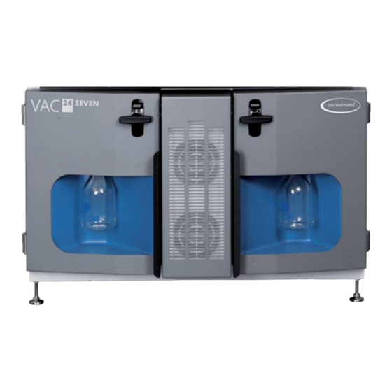
Description of pump module Description of pump module Description of pump module 2.1 Product description Product description Pump module views Example Pump module front view Example Pump module rear view Centering devices for adjustable feet of the control module Isolation valve for vacuum pump suction line, rotary handle also serves to lock the door Door handle... - Page 8 Description of pump module Pump module side view (1 cable channel hidden) Inlet IN, KF DN 50 (suction line) Rating plate Outlet OUT, KF DN 50 (exhaust gas line) Door hinge Cable duct Machine feet, screwed in (only in the lowest pump module) 20901461_EN_VAC_24-7_Pump_V1.1_211221...
-
Page 9: Function Description
Description of pump module 2.2 Function description Function description Pump module in general Depending on the requirements, up to 3 pump modules can be controlled and regu- Function description lated with one control module. Pump modules are available in two different versions: 5 mbar ultimate vacuum and 30 m³/h pumping speed or ƒ... - Page 10 Description of pump module Status display for monitoring The operating status of the vacuum pumps is displayed using the light column, the Display elements status LEDs, and the rocker switches on the front of the control module. Connections Various connections The following connections are located on the pump module: Vacuum connection for the process = suction line.
-
Page 11: Operation Of The Pump Module
Operation of the pump module Operation of the pump module Operation of the pump module The vacuum pumping unit is operated at the control module. Switch on/off the vacuum pumping unit, ƒ Switch vacuum pumps on/off individually, ƒ Control gas ballast supply. ƒ... -
Page 12: Switch On/Off Vacuum Pump
Operation of the pump module 3.2 Switch on/off vacuum pump Switch on/off vacuum pump After switching on the control module, it may first be necessary to switch on the vacuum pumps of a pump module. If maintenance must be performed, the vacuum pump of a pump module can be switched off, removed, and serviced separately. -
Page 13: Gas Ballast - Control Supply
Operation of the pump module 3.3 Gas ballast – control supply Gas ballast – control supply The supply of gas ballast, e.g., air or inert gas, is intended to prevent the formation of condensate in the vacuum pump or to flush possible pump residues out of the vacuum pump. - Page 14 Operation of the pump module 20901461_EN_VAC_24-7_Pump_V1.1_211221...
-
Page 15: Error Remedy
Error remedy Error remedy Error remedy 4.1 Error – Cause – Remedy Error – Cause – Remedy Error Error ` Possible cause 3 Remedy Personnel Error-Cause-Remedy Sensitive ` Speed too high Reduce speed Operator, specialist process not ` Pumping speed too controllable high Vacuum pump... - Page 16 Error remedy Error Error ` Possible cause 3 Remedy Personnel Error-Cause-Remedy Pump module ` Fan fabric clogged. Test the fan function: Briefly switch the vacuum pumps gets too hot ` Fan front covered. of pump module OFF and ` Fan failure. ON again ...
-
Page 17: Technical Support
Error remedy 4.2 Technical support Technical support For technical assistance or in the event of an error, please contact our Service Technical support Department. > To identify errors and potential remedies, please refer to the troubleshooting table Error – Cause – Remedy Error –... -
Page 18: Service Work
Service work Service work Service work NOTE NOTE Damage possible if work is performed incorrectly. Have maintenance work performed by a trained professional or at least by a > trained person. Recommendation: Please read before the first maintenance the complete >... -
Page 19: Pump Module - Remove Vacuum Pump
Service work 5.2 Pump module – remove vacuum pump Pump module – remove vacuum pump The removal of a vacuum pump is provided for in the following cases: Service work such as cleaning and maintenance ƒ Repairing a vacuum pump ƒ... - Page 20 Service work Note the following during maintenance work: IMPORTANT! If the pumping unit is operated at the ultimate vacuum with closed gas ballast valve, a slight increase in pressure is possible while, for example, the flask is emptied or a vacuum pump is removed for service work. >...
- Page 21 Service work Remove vacuum pump WARNING! Risk of burns due to hot exhaust gas pipe. > Wear heat-resistant safety gloves. > Switch off the parallel vacuum pump as long as the exhaust gas line is open. 7. 7. Remove the clamping ring from the 8.
- Page 22 Service work Remove vacuum pump Remove transport lock 9. 9. Fix the hexagon nut with a fork Fittings of the transport lock. wrench size SW 10 and unscrew the hexagon socket screw. Hex key size 5 5 Transport lock can be moved. IMPORTANT! Keep the transport lock for a possible later transport.
- Page 23 Service work Remove vacuum pump 12. Push back the metal ring of the 13. Close the gas ballast hose with a plug coupling and pull out the gas blanking plug. ballast hose. NOTICE NOTICE Depending on the type of vacuum pump and the installation position, the gas ballast hose can also be fit on the side.
- Page 24 Service work Remove vacuum pump 16. Put aside the cable of the vacuum 17. Unscrew the 2 hexagon sock- pump. et screws, which fix the vacuum pump. Hex key size 5. 18. Take out the vacuum pump with 19. Place the vacuum pump on a sta- both handles.
-
Page 25: Information On Service Work
Service work 5.3 Information on service work Information on service work WARNING Risk of injury from hazardous substances and contaminated components. Pumping hazardous media can result in hazardous substances adher- ing to internal parts of the pump. Always wear your personal protective equipment when perform- >... - Page 26 Service work Tool set from accessories, recommended Example Maintenance set accessory from VACUUBRAND Tool set for 8-cylinder NT pumps Size #20649918 Assembly stand 8Z NT Hex key Loosen/secure transport lock Size 5 Loosen/secure pump foot Size 5 Loosen/secure head cover...
- Page 27 Service work Tools for maintenance, additional Example Overview of required tools Tool set for 8-cylinder NT pumps Size #20649918 Hex key Loosen/secure transport lock Size 5 Loosen/secure pump foot Size 5 Loosen/secure head cover Size 5 Loosen/secure air inlet Size 2.5 Flat-head screwdriver Open hose clamps...
-
Page 28: Servicing A Vacuum Pump (Diaphragm + Valves)
Service work 5.3.2 5.3.2 Servicing a vacuum pump (diaphragm + valves) Servicing a vacuum pump (diaphragm + valves) Items that require maintenance Example Front view of vacuum pump Maintenance items Top pump head pair Pump head pair right Suction/pressure distributor (behind outlet condenser OC) Bottom pump head pair Left pump head pair... - Page 29 O-rings 26 x 2 Diaphragm maintenance in the mainte- nance set Head cover + screw fittings Diaphragm clamping disc with square-head screw Diaphragm Diaphragm support disc Spacer discs, max. 4 Maintenance set VAC 24seven for one pump module 20696881 20901461_EN_VAC_24-7_Pump_V1.1_211221...
- Page 30 Service work Replace the diaphragms Example Diaphragm replacement with assembly stand from tool set #20649918 1. 1. Open the clamping ring of the outlet 2. 2. Remove the outlet condenser and condenser (OC). put aside the outlet condenser, clamping ring, and centering ring. 3.
- Page 31 Service work Side view: Molded hoses of pump head pair. 4. 4. Open the hose clamps of the hos- 5. 5. Pull the molded hoses off the hose es of a pump head pair. Flat-head nozzles. screwdriver size 1. 20901461_EN_VAC_24-7_Pump_V1.1_211221...
- Page 32 Service work 6. 6. Unscrew the socket head screws 7. 7. Lift the pump head pair along with from the head covers. Hex key all the screw fittings of the vacuum size 5. pump. 8. 8. Set the pump head pair aside. 9.
- Page 33 Service work 10. Fold the diaphragm forward at the 11. Use the fixed diaphragm wrench to sides and carefully place the dia- screw out the assembly. phragm wrench on the diaphragm support disc. 12. Lift the diaphragm along with all the IMPORTANT! IMPORTANT! parts out of the vacuum pump.
- Page 34 Service work 13. Pull out the diaphragm clamp- ing disc and remove the used dia- phragm. IMPORTANT! IMPORTANT! 14. Place the new diaphragm over the square head of the clamping disc. > Ensure that the diaphragm is insert- ed correctly, with the coated, light- colored side facing upwards.
- Page 35 Service work 15. Place all spacer discs on the 16. Secure the diaphragm assembly thread pin. inside the diaphragm wrench. 17. Hold the spacer discs firmly and 18. Initially tighten the assembly with place all the components carefully the diaphragm wrench by hand. on the connecting rod thread.
- Page 36 Service work 19. Then position a torque wrench with 20. Repeat the steps for the second socket head bit on the diaphragm diaphragm. wrench and tighten the assembly to 6 Nm. 20901461_EN_VAC_24-7_Pump_V1.1_211221...
- Page 37 Service work Replace the valves 1. 1. Take the pump head pair which you 2. 2. unscrew the Torx screws. Torx had set aside and screwdriver Tx20 3. 3. Remove the clamping brackets 4. 4. Lift both valve terminals from the from the valve terminals.
- Page 38 Service work Top view: Valve terminals, valves and pump head pair. 5. 5. Carefully remove the used valves, 6. 6. Carefully remove the used O-rings. e.g., with a sturdy plastic rod or a narrow flat-head screwdriver. 20901461_EN_VAC_24-7_Pump_V1.1_211221...
- Page 39 Service work 7. 7. Check the surfaces for dirt. 8. 8. Clean dirty surfaces carefully. IMPORTANT! IMPORTANT! > No particles or dirt may get inside the vacuum pump. 9. 9. Insert the new sealing rings into the 10. Place the new valves on top and grooves.
- Page 40 Service work 11. Compare the valve positions with 12. Place the two valve terminals on this illustration. the pump heads again. Here as IN = Inlet (inlet) well, compare the correct position EX = Exhaust (outlet) of IN and EX with the labeling on the valve terminals.
- Page 41 Service work 15. Carefully press the diaphragms 16. Hold the pump head pair at the vac- centrally into the housing opening, uum pump and wind in the screw ensuring they are flush with it. fittings. 17. Tighten the screw fittings crosswise 18.
- Page 42 Service work 19. Slide the molded hoses back onto 20. Secure the hose clips on the hose the hose nozzles. nozzles, e.g., with flat nose pliers. NOTE NOTE Always maintain the diaphragm and inlet/outlet valves of a vacuum pump completely. Service all pump heads as described in the chapters Replace the dia- Replace the dia- >...
-
Page 43: Suction/Pressure Distributor Maintenance
Error remedy 5.3.3 5.3.3 Suction/pressure distributor maintenance Suction/pressure distributor maintenance Exploded drawing of suction/pressure distributor (No. 4 on Page 28 Page 28) Example Suction/pressure distributor Vacuum pump Maintenance overpressure relief valve + O-ring Countersunk screw M4x80 Connection DN 25 Hose nozzle Suction distributor O-ring 40 x 2... - Page 44 Error remedy Replace pressure relief valve + O-ring 1. Place the vacuum pump on a clean, 2. 2. Open the 4 small upper hose stable surface as shown. Stabilize clamps, see arrow markings. Flat- the vacuum pump so that it cannot head screwdriver size 1.
- Page 45 Error remedy 5. 5. Pull the screws out of the pressure 6. 6. Remove the suction distributor and distributor. set it aside. 7. 7. Carefully remove the used pres- 8. 8. Carefully remove the used O-ring. sure relief valve, e.g., with a stur- dy plastic rod or a narrow flat-head screwdriver.
- Page 46 Error remedy 9. 9. Clean the surface if dirty. 10. Place the new O-ring in the groove and press it down slightly. Bottom 11. Place the new pressure relief valve Top view: on the clean surface. Correct positioning of pressure relief valve on pressure distributor.
- Page 47 Error remedy 12. Position the suction distributor with 13. Push the molded hoses back into the screw fittings and hand-tight- place on the hose nozzles. en the screw fittings. PH2 Phillips screwdriver. During maintenance work, you can clean the molded hoses (PTFE/ white).
- Page 48 Error remedy 14. Slide the hose clamps onto the 15. Clean the centering ring on both hose nozzle and close them with sides. the flat nose pliers. 16. Clean the flanges from the outlet 17. Place the centering ring between condenser and the suction/pres- the flanges and fasten the outlet sure distributor.
-
Page 49: Reinsert The Vacuum Pump
Error remedy 5.3.4 5.3.4 Reinsert the vacuum pump Reinsert the vacuum pump Once all maintenance work, such as the replacement of diaphragms, valves, and O-rings, has been completed, the vacuum pump can be reinserted in the pump module. 1. 1. Pull out the sliding guides up to the 2. - Page 50 Error remedy 5. 5. Push back the metal ring of the 6. 6. Slide the gas ballast hose into the plug coupling and pull out the plug coupling at the vacuum pump blanking plug. and test the hose locking with a gentle jerk.
- Page 51 Error remedy 9. 9. Push the vacuum pump inside until NOTICE! the suction- and exhaust pipe are > Switch off the parallel vacuum placed directly in front of its con- pump as long as the exhaust gas nection. line is open. 10.
- Page 52 Error remedy 13. Close the maintenance door. 14. Screw in the condensate catch pot. 15. Switch on the vacuum pump at 16. Turn the black handle of the isola- rocker switch. tion valve 90° in either direction. 5 Vacuum pump(s) in operation. 5 Handle in horizontal position.
-
Page 53: Clean Air Inlet
Error remedy 5.3.5 5.3.5 Clean air inlet Clean air inlet Depending on the operating conditions, particles, dust, or similar matter may ad- here to the air inlet of the pump module. We recommend checking the air inlet at weekly or monthly intervals, taking into account the operating conditions, and cleaning the fan fabric if dirty. -
Page 54: Replace Fan Fabric
Error remedy 5.3.6 5.3.6 Replace fan fabric Replace fan fabric WARNING Risk of injury from rotating fans. When the vacuum pumps are switched on, the cooling fans run auto- matically. If the air inlet is removed, the fan blades no longer have a cover. - Page 55 Error remedy 3. 3. Screw out both condensate catch 4. 4. Open the maintenance doors. pots. 5 Screw fittings of the air inlet freely accessible. 5. Unscrew the screw fittings of the Front view: air inlet halfway. Positions of the fastening screws. 20901461_EN_VAC_24-7_Pump_V1.1_211221...
- Page 56 Error remedy 6. 6. Remove the air inlet. 7. 7. Place the air inlet on a clean work surface. 8. 8. Unscrew the hexagon nuts on the 9. 9. Lift the filter clamping plate out of filter clamping plate. the air inlet. 20901461_EN_VAC_24-7_Pump_V1.1_211221...
- Page 57 Error remedy 10. Remove the fan fabric. 11. Place the new fan fabric in the air inlet. 12. Tighten the hexagon nuts of the fil- 13. Slide the air inlet back onto the ter clamping plate. fans. 20901461_EN_VAC_24-7_Pump_V1.1_211221...
- Page 58 Error remedy 14. Hand-tighten all screw fittings of the 15. Close the maintenance doors. fan inlet. 16. Screw the condensate catch pots 17. Switch the vacuum pumps on into the pump module so they are again. hand-tight. 5 Fan fully activated for 10 sec. 5 Vacuum pumps in operation.
- Page 59 Error remedy 18. Turn the black handles of the isola- 19. Switch on the two vacuum pumps tion valve by 90° in either direction. of the pump module. 5 Handles in horizontal position. 5 Vacuum pumps stopped. 5 In-line solenoid valves open. 5 Status LED turns GREEN GREEN.
-
Page 60: Empty The Condensate Catch Pot
Error remedy 5.3.7 5.3.7 Empty the condensate catch pot Empty the condensate catch pot DANGER DANGER Risk of explosion from sparks. Emptying electrostatically charged glass containers may create sparks, which can ignite explosive mixtures of gases and vapors. Wear your personal protection equipment when handling hazardous >... - Page 61 Error remedy 3. 3. Carefully unscrew the condensate 4. 4. Remove the condensate catch pot catch pot from the thread. from the pump module. 5. Empty the contents of the pot into 6. 6. Screw the empty condensate catch a container. pot into the pump module so it is hand-tight.
- Page 62 Error remedy 7. 7. Switch on the vacuum pump at 8. 8. Turn the black handle of the isola- rocker switch. tion valve 90° in either direction. 5 Vacuum pump in operation. 5 Handle in horizontal position. 5 Status LED turns GREEN GREEN.
-
Page 63: Appendix
IP42 Pollution degree II 3/- G Ex h IIC T3 Gc X Internal Atm. ATEX conformity, interior Only; Tech. File: VAC-EX02 Pump module #70 mbar VAC 24seven (US) End vacuum, absolute 70 mbar 52.5 Torr End vacuum with gas ballast, absolute... -
Page 64: Wetted Materials
Appendix Operating conditions Operating conditions (US) Working temperature 10 – 45 °C 50 – 113 °F Storage/transport temperature -10 – 60 °C 14 – 140 °F Maximum admissible media temperature non-explosive atmosphere: Gas temperature range Short term 80 °C 176 °F Continuous operation 10 –... -
Page 65: Rating Plate
Appendix Sealing/centering ring at separator (OC) Adapter KF 25 to hose nozzle 15 mm (OC) 6.1.3 6.1.3 Rating plate Rating plate > In the event of an error, make a note of the type and serial number on the rating plate. >... - Page 66 Pump module 70 mbar 20745118 Spare parts for VAC 24seven Ordering information Order no. spare parts Maintenance set VAC 24seven for one pump module 20696881 Separator OC for condensate, suction-side 20635437 Flask for separator OC, 500 ml, with thread GL 45 20635468...
-
Page 67: Index
Appendix 6.2 Index Index Replace the valves ........37 Admissible pressure ranges ......64 Right vacuum pump........18 Air inlet............18 ATEX specification (rating plate) ....65 Secure against being switched on again ..11 Service vacuum pump ........28 Check vacuum pump ........ -
Page 68: Declaration Of Incorporation (Eu)
Déclaration d’incorporation des machines Hersteller / Manufacturer / Fabricant: VACUUBRAND GMBH + CO KG VACUUBRAND GMBH + CO KG · Alfred-Zippe-Str. 4 · 97877 Wertheim · Germany Hiermit erklärt der Hersteller, dass die unvollständige Maschine konform ist mit den Bestimmungen dieser Richtlinien:... - Page 69 Bevollmächtigter für die Zusammenstellung der technischen Unterlagen / Person authorised to compile the technical file / Personne autorisée à constituer le dossier technique: Dr. Constantin Schöler · VACUUBRAND GMBH + CO KG · Germany Ort, Datum / place, date / lieu, date: Wertheim, 29.11.2021 ppa.
-
Page 70: Declaration Of Incorporation (Uk)
The Restriction of the Use of Certain Hazardous Substances in Electrical and ƒ Electronic Equipment Regulations 2012 (S.I. 2012 No. 3032) Product / Type: Vacuum pumping unit / VAC 24seven pump module #5 mbar, VAC 24seven pump module #70 mbar Order number: 20745318, 20745118... - Page 71 20901461_EN_VAC_24-7_Pump_V1.1_211221...
- Page 72 Technology for Vacuum Systems Manufacturer: VACUUBRAND GMBH + CO KG VACUUBRAND GMBH + CO KG Alfred‑Zippe‑Str. 4 Alfred‑Zippe‑Str. 4 97877 Wertheim 97877 Wertheim GERMANY GERMANY Phone: Head office: +49 9342 808‑0 Sales: +49 9342 808‑5550 Service: +49 9342 808‑5660 Fax: +49 9342 808‑5555...
Need help?
Do you have a question about the VAC 24seven and is the answer not in the manual?
Questions and answers