vacuubrand VAC 24seven Instructions For Use Manual
Hide thumbs
Also See for VAC 24seven:
- Instructions for use manual (50 pages) ,
- Instructions for use manual (72 pages) ,
- Instructions for use manual (10 pages)

Related Manuals for vacuubrand VAC 24seven


Summary of Contents for vacuubrand VAC 24seven
- Page 1 Description of vacuum controller Technology for Vacuum Systems Control module Vacuum controller VACUU·SELECT Instructions for use Original instructions EN OI no.: 20901531...
- Page 2 Service: +49 9342 808‑5660 Fax: +49 9342 808‑5555 Email:info@vacuubrand.com Web: www.vacuubrand.com Thank you for purchasing this product from VACUUBRAND GMBH + CO KG VACUUBRAND GMBH + CO KG . You have chosen a modern and techni‑ cally high quality product. 20901531_EN_VACUU·SELECT_V1.0_010621...
-
Page 3: Table Of Contents
Content TABLE OF CONTENTS About this document User information ......... . . 5 1.1.1 Descriptions of the control module . - Page 4 Content 5.1.8 Settings/administration....... 42 5.1.9 Administration – import/export ......44 5.1.10 Administration –...
-
Page 5: About This Document
Safety Intended use Intended use The vacuum controller in the control module is part of the VAC 24seven vacuum pumping unit and is designed for the measurement and control of vacuums in systems intended for this purpose. Any other use is considered improper use. -
Page 6: Symbols And Pictograms
About this document 1.1.4 1.1.4 Symbols and Symbols and pictograms pictograms Safety symbols Explanation General of safety symbols Danger: electricity. warning sign. Electrostatically sensitive com‑ ponents ESD. Additional symbols and pictograms Additional Positive example – Do this! Do this! Negative example – symbols Result –... -
Page 7: Handling Instructions (Action Steps)
About this document 1.1.5 1.1.5 Handling instructions ( Handling instructions (action steps) action steps) Instructions (single step) Action steps as text > Perform the step described. 5 Result of action Instructions (multiple steps) 1. First step 2. 2. Next step 5 Result of action Perform the steps in the order described. -
Page 8: Term Definitions
Rough vacuum Pressure measuring range in vacuum technology, from: atmospheric pressure 1 mbar (0.75 Torr) VACUU·BUS Bus system from VACUUBRAND for communication ® between peripheral devices with VACUU·BUS enabled gauges and controllers. The maximum permissible cable length is 30 m. -
Page 9: Product Description
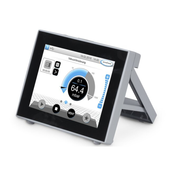
Product description Product description Product description 2.1 VACUU·SELECT vacuum controller VACUU·SELECT vacuum controller The VACUU SELECT vacuum controller is a vacuum controller consisting of an operating panel with touchscreen and various interfaces, such as USB‑A as well as VACUU BUS and Ethernet, which are led out on the rear of the control module. The controller was developed for applications which require a controlled vacuum. -
Page 10: Remote Control And Interfaces
About this document 2.3 Remote control and interfaces Remote control and interfaces The vacuum controller in the control module supports communication via Mod‑ bus TCP and RS‑232. This allows you to monitor or control the vacuum pumping unit remotely from a central location, e.g., with a PC or process control system. 2.3.1 2.3.1 Modbus TCP... -
Page 11: Rs-232 Serial Interface
About this document 2.3.2 2.3.2 RS-232 serial interface RS-232 serial interface As a serial interface, you can connect an RS‑232 USB adapter to the USB port on the rear of the control module. Example RS‑232 connection on the control module Required accessories Adapter cable, USB to RS‑232, 1 m 20637838... - Page 12 About this document 20901531_EN_VACUU·SELECT_V1.0_010621...
-
Page 13: User Interface
User interface User interface User interface 3.1 Switch on controller Switch on controller Switch on device > Briefly press the ON/OFF button on the controller 5 Device starts up. 5 Information is displayed Functions of the ON/OFF button ON/OFF Description ON/OFF button Switch on controller Switch on controller... -
Page 14: Touchscreen
User interface 3.1.1 3.1.1 Touchscreen Touchscreen The controller is a device operated via touchscreen. You can, for example, select, Touchscreen operation start, and stop an application by tapping the display. Different gestures allow you to use advanced functions of the device: Switch be‑ tween displays, edit applications, or use help and context features. -
Page 15: Adjust The Screen Orientation
User interface For subsequent adjustments to the data logger See chapter: 5.2 Data logger on page 48 5.2 Data logger on page 48 For subsequent adjustments to the diagnostic data See chapter: 5.3 Service on page 49 5.3 Service on page 49 3.2.2 3.2.2 Adjust the screen orientation... -
Page 16: Display And Operating Elements
User interface 3.3 Display and operating elements Display and operating elements The display and operating elements of the controller are summarized and explained Examples in this chapter. Pop‑up window > Refer to this chapter if you want to read about the meaning of a display or an operating element during operation. -
Page 17: Display Elements
User interface 3.3.2 3.3.2 Display elements Display elements Status bar Color Description Status bar color codes Gray Gray Standard Standard Yellow Warning Warning Error Error Sounds Sound Description Sounds Touch tone unless muted Touch tone unless muted ` Feedback entry Warning or error Warning or error ` Shows that an error or warning is present. - Page 18 User interface Pop-up windows (context menus) Graphic Description Examples Pop‑up window Numeric keypad with special buttons Numeric keypad with special buttons ` Enter numerical values. ` Select a function using special buttons (AUS, ATM, AUTO). ` Min./max. values displayed. ` Values outside the permissible input range are not accepted.
-
Page 19: Operating Elements And Symbols
User interface 3.3.3 3.3.3 Operating elements and symbols Operating elements and symbols Status bar Symbol (icon) Description Access help Access help ` Tips for operation can be accessed from any menu level. USB connected USB connected ` Shows that a storage device is connected via USB. (option) Ethernet connected Ethernet connected... - Page 20 User interface Operating elements – adjust pressure setpoint Symbol (icon) Description Pressure curve – analog pressure display Pressure curve – analog pressure display ` Adjust the pressure setpoint by moving the marker. Marker – pressure setpoint Digital pressure display Digital pressure display ` Adjust the pressure setpoint by tapping.
- Page 21 User interface Operating elements – process steps Button or icon Description active Locked Application icon Application icon ` Tap briefly: Open the parameter list. ` Press and hold: Open the context menu. Shortcut Shortcut ` Open the applications menu. Right/left arrow Right/left arrow Process screen ` Open/close the process step display.
- Page 22 User interface Input field or selection field Input field or selection field Parameter list ` Tap to open a pop‑up window where you can enter val‑ ues or select a function, even during operation. Blue Blue Input field for active process Black Black Input field for inactive process...
-
Page 23: Operation
Operation Operation Operation The controller has an application‑based user interface. You can select, edit and start an application from a series of pre-defined applications. Fine adjustments for the selected application can be made at any time in the parameter list or directly via the 3.3.3 Operating elements and symbols on page 19 3.3.3 Operating elements and symbols on page 4.1 Applications... -
Page 24: Adjust Pressure Setpoint
Operation 4.1.2 4.1.2 Adjust pressure setpoint Adjust pressure setpoint The controller offers a variety of options for adjusting the pressure setpoint during operation. Change pressure setpoint in the parameter list Touch, tap > Enter a target value in the pop‑up and confirm the entry 2x. - Page 25 Operation Adjust pressure setpoint using marker Hold down and drag Release Adjust pressure setpoint in digital pressure display Touch, tap > Enter a target value in the pop‑up and confirm the entry. 20901531_EN_VACUU·SELECT_V1.0_010621...
-
Page 26: Stop Application
Operation 4.1.3 4.1.3 Stop application Stop application Stop application > Touch, tap Vacuum control stops. 4.2 Application parameters ( Application parameters (parameter list) parameter list) In the parameter list, you can individually change and adapt various process‑relat‑ ed values before and during operation. Adjust parameter ... - Page 27 Operation Example Adjust speed parameter 3. Enter the required speed in the pop‑up. 4. 4. Confirm entry. Cancel Confirm Touch, tap 5. Confirm the change in the parameter Once the application starts, the list. motor runs at the adjusted speed. ...
-
Page 28: Pressure Graph
Operation 4.3 Pressure graph Pressure graph The pressure graph is on the same level as the process screen. The menu shows pressure curves of measured vacuum values. The pressure curve is shown until a new application is started, at which point it is replotted. View pressure curve >... -
Page 29: Main Menu
Operation 4.4 Main menu Main menu The main menu is on the same level as the process screen. The submenus of the controller can be accessed from the main menu. View main menu > Example View main menu Swipe right >... -
Page 30: Applications
Operation 4.4.1 4.4.1 Applications Applications This menu lists all applications: standard applications, favorites, and newly created applications. View application menu View applications > submenu Touch, tap Display the applications submenu. Show context menu Example > View context menu for applications ~ 3 sec The context menu appears. -
Page 31: Favorites
Operation 4.4.2 4.4.2 Favorites Favorites Applications marked as favorites are identified by a star on the button. Add favorites Example Add favorites ~ 3 sec Hold down Touch, tap Confirm Text changed in the context menu. Button with favorites star. Application listed in favorites menu. - Page 32 Operation 20901531_EN_VACUU·SELECT_V1.0_010621...
-
Page 33: Main Menu
Main menu Main menu Main menu 5.1 Advanced operation Advanced operation 5.1.1 5.1.1 Application editor Application editor In the application editor, you can compile your own application using the building‑ block principle and save it with an appropriate name. Existing applications can be used in the application editor as templates, and then saved with a new name. -
Page 34: Menu Bar And Description
Main menu Application editor display Hold vacuum > Tool tips help when selecting process steps. Menu bar Overview of process steps Building blocks with individual process steps which you can scroll through and select as required. 5.1.2 5.1.2 Menu bar and description Menu bar and description Menu bar Icon buttons... -
Page 35: Overview Of Process Steps
Main menu Description of the application New application: this name is automatically changed as soon as you give your application an appropriate name using Save as . Description of the new application: here, you can enter a brief description of your application. -
Page 36: Process End
Main menu 5.1.4 5.1.4 Process end Process end Process end means the defined end of an application. Process steps can only be placed above this. 20901531_EN_VACUU·SELECT_V1.0_010621... -
Page 37: Edit Application
Main menu 5.1.5 5.1.5 Edit application Edit application Create a new application Example Create a new applica‑ tion Touch, tap Hold down and drag Release Save as Confirm Exit menu 20901531_EN_VACUU·SELECT_V1.0_010621... - Page 38 Main menu Example Edit new application Touch, tap Hold down Save Confirm Exit menu 5 New application listed with white sym‑ bol in applications submenu. 20901531_EN_VACUU·SELECT_V1.0_010621...
-
Page 39: Remove Process Step
Main menu 5.1.6 5.1.6 Remove process step Remove process step Change application Example Edit existing application Hold down Touch, tap Hold down and drag Release Save Exit menu 5 The removed process step is no longer displayed in the parameter list of the application. -
Page 40: Settings
Main menu 5.1.7 5.1.7 Settings Settings In this submenu you can adjust the display, switch to another language, and make presettings for connected VACUU·BUS VACUU·BUS peripheral devices. View settings submenu > Example Main menu \ Settings \ Basic settings Touch, tap Description of context menus Under Display, you can specify various... - Page 41 Main menu You can specify presettings for your pro‑ Example cess in Basic Settings: Overview of context menus Settings Description of basic settings Overview of possible Function Setting Description basic settings Autostart* Off / On Off: The controller remains on Stop when the power supply is switched on.
-
Page 42: Settings/Administration
Main menu 5.1.8 5.1.8 Settings/administration Settings/administration Admin area of the controller – only for authorized staff. View administration submenu Example Main menu \ Settings \ Administration Touch, tap 5 Submenu with buttons for administra‑ tive submenus. Description of context menus Adjustments for date and time. - Page 43 Main menu Presettings for adding the controller to your network. Activate/deactivate remote control via Modbus. Default settings for serial interface and alignment of the communication settings (COM) for RS‑232. Activate/deactivate remote control via RS‑232. Install software update from connected USB flash drive. Reset the controller to the factory set- tings.
-
Page 44: Administration - Import/Export
Main menu 5.1.9 5.1.9 Administration – import/export Administration – import/export Calling up the Import/Export submenu Example > Main menu \ Settings \ Administration \ Import/Export Touch, tap Description of context menus You can use the export function to trans‑ ... -
Page 45: 5.1.10 Administration - Vacuu·bus
Main menu 5.1.10 5.1.10 Administration – VACUU·BUS Administration – VACUU·BUS The VACUU·BUS VACUU·BUS submenu simplifies the detection and management of VACUU·BUS VACUU·BUS components. View the VACUU·BUS submenu Example > Main menu \ Settings \ Administration \ VACUU·BUS Touch, tap The buttons retrieve context menus. - Page 46 Main menu Using component activation, connected Overview of VACUU·BUS components can be indi‑ VACUU·BUS context vidually activated or deactivated, i.e., the menus components can remain connected but are switched on or off at the controller as required for the ongoing process. Cancel Confirm Control panel for the calibration of...
-
Page 47: Administration/Function Extensions
Confirm Function activation If you have a valid license, please follow the user prompts that appear once you have inserted the USB stick with the license file. Alternatively, you can enter the license code using the on‑screen keyboard. https://www.vacuubrand.com/20901537 20901531_EN_VACUU·SELECT_V1.0_010621... -
Page 48: Data Logger
Main menu 5.2 Data logger Data logger If the function is switched on, the data logger records time/pressure curves and saves these at specified intervals, for a duration of up to 30 days. A separate data file is saved for each process, from start to stop. View data logger submenu ... -
Page 49: Service
Main menu 5.3 Service Service In this menu, you can find or download information about the device. In the event of an error, please forward this information to our Service Department. 5.3.1 5.3.1 Service information Service information View service submenu >... -
Page 50: Diagnostic Data
Main menu 5.3.2 5.3.2 Diagnostic data Diagnostic data To improve the diagnostics of the device condition in the event of an error or service, diagnostic data is stored on the device. The data can be downloaded onto a USB flash drive via the service menu and sent to our Customer service for evaluation. - Page 51 Main menu 20901531_EN_VACUU·SELECT_V1.0_010621...
-
Page 52: Troubleshooting
Troubleshooting Troubleshooting Troubleshooting To identify errors and potential remedies, please refer to the troubleshooting table Technical Error – Cause – Remedy Error – Cause – Remedy. support For technical assistance or errors for which you require additional support, please contact your local distributor or our Service Department 6.1 Error messages Error messages... -
Page 53: Acknowledge Error Message
Troubleshooting 6.1.2 6.1.2 Acknowledge error message Acknowledge error message Error messages must be acknowledged after the error has been remedied. View and acknowledge error message View message Acknowledge Touch, tap 5 Error message reset. 20901531_EN_VACUU·SELECT_V1.0_010621... -
Page 54: Error - Cause - Remedy
Troubleshooting 6.2 Error – Cause – Remedy Error – Cause – Remedy 6.2.1 6.2.1 Pop-up message Pop-up message Error Error ` Possible cause Remedy Personnel Error – Cause – Remedy Specialist Communication One or more Deactivate relevant error VACUU·BUS components VACUU·BUS compo‑... -
Page 55: General Errors
Troubleshooting Error Error ` Possible cause Remedy Personnel Error – Cause – Remedy Operator Maximum liquid Full status indicator of a Empty the glass flask or level reached level sensor. container in question. Level sensor removed. Connect level sensor. ... - Page 56 Troubleshooting Error Error ` Possible cause Remedy Personnel Error – Cause – Remedy Resp. spe- No operation pos‑ Operation taken over Have operation enabled cialist sible from external terminal and from external terminal. operation blocked in the controller. Operator Screen orientation Display orientation acci‑...
- Page 57 Troubleshooting 20901531_EN_VACUU·SELECT_V1.0_010621...
-
Page 58: Appendix
Appendix Appendix Appendix 7.1 Technical information Technical information Version of vacuum Version controller Vacuum controller VACUU·SELECT VACUU·SELECT ® Software version V1.06 / V1.00 Technical data Technical data Ambient conditions (US) Working temperature 10–40 °C 50–104 °F Storage/transport temperature ‑10–60 °C 14–140 °F Altitude, max. -
Page 59: Licensing Information And Data Protection
Appendix 7.2 Licensing information and data protection Licensing information and data protection > This product contains open source software. The associated licens‑ ing information can be found in the VACUU·SELECT, in the service menu under the heading Legal notices About the device About the device Legal notices >... -
Page 60: Index
Appendix 7.3 Index Index Process screen ..........16 Abbreviations ..........7,8 Process step ..........35 Action step ............7 Process step configuration ......35 Activate/deactivate Modbus......43 Process step section ........35 Activate/deactivate RS‑232 ......43 Product-specific terms ........8 Activate/deactivate VACUU BUS components .. - Page 61 20901531_EN_VACUU·SELECT_V1.0_010621...
- Page 62 Technology for Vacuum Systems Manufacturer: VACUUBRAND GMBH + CO KG VACUUBRAND GMBH + CO KG Alfred‑Zippe‑Str. 4 Alfred‑Zippe‑Str. 4 97877 Wertheim 97877 Wertheim GERMANY GERMANY Phone: Head office: +49 9342 808‑0 Sales: +49 9342 808‑5550 Service: +49 9342 808‑5660 Fax: +49 9342 808‑5555...
Need help?
Do you have a question about the VAC 24seven and is the answer not in the manual?
Questions and answers