PMFoundations ER-808 Button Bus PCB Assembly Manual
Hide thumbs
Also See for ER-808 Button Bus PCB:
- Assembly manual (16 pages) ,
- User manual (5 pages) ,
- Assembly manual (5 pages)

Related Manuals for PMFoundations ER-808 Button Bus PCB


Summary of Contents for PMFoundations ER-808 Button Bus PCB
- Page 1 ER-808 – Assembly Guide _____________________________________________________________________________________ PM Foundations ER-808 v1.4 Button Bus PCB _____________________________________________________________________________________ Page 1 of 12...
-
Page 2: Power Socket
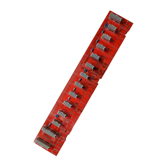
ER-808 – Assembly Guide _____________________________________________________________________________________ Introduction This guide is for the push button version. If you are building the Touch Version of the Drum Machine, please refer to the Touch Bus PCB manual. Since the Bus PCB is common to this and the Touch version, there are many unused locations. Please follow this guide and install ONLY the parts listed in the BOM for the Button version. - Page 3 ER-808 – Assembly Guide _____________________________________________________________________________________ Module headers Install the 20, 10 and 16 pin straight control plugs on the TOP of the board. These must be installed with the correct orientation or the module will be damaged when the power is connected. The PROTRUSION on the socket should face the 10, 20 or 16 markings on the board outline, as shown in the photo.
- Page 4 ER-808 – Assembly Guide _____________________________________________________________________________________ _____________________________________________________________________________________ Page 4 of 12...
- Page 5 ER-808 – Assembly Guide _____________________________________________________________________________________ Standoffs Install the 2 standoffs for attaching the front panel. Lighted switches Carefully insert the leads into the holes for the switch pins and LED pins. The plastic legs of the switch must be flat onto the surface of the PCB. Any plastic legs which are fouled by other component pins should be cut off so the switch can lie flat (SW6, 7, 13, 14, 16).
- Page 6 ER-808 – Assembly Guide _____________________________________________________________________________________ _____________________________________________________________________________________ Page 6 of 12...
- Page 7 ER-808 – Assembly Guide _____________________________________________________________________________________ For SW1 and SW2 cut off one pin of each switch where it protrudes into the header on the top. This obstruction can be clearly seen in the pad. Double check the alignment and cut the correct pin. When soldering the switch, this pin can be ignored.
- Page 8 ER-808 – Assembly Guide _____________________________________________________________________________________ _____________________________________________________________________________________ Page 8 of 12...
-
Page 9: Initial Testing
ER-808 – Assembly Guide _____________________________________________________________________________________ Align the switches so they fit exactly in line with the board outlines so they do not foul the front panel. Initial Testing Gather the completed Accent, Main/Control and Bus PCBS. Do not install the ICs yet. ... - Page 10 ER-808 – Assembly Guide _____________________________________________________________________________________ 16: 0 17: 0 18: 0 19: 0 20: 0 21: 0 22: 0 23: 3.3 24: 0 25: 0 26: 3.3 27: 0 ...
- Page 11 ER-808 – Assembly Guide _____________________________________________________________________________________ Join the Main/Control module to the Accent module using the 16 pin headers Assemble the main /accent sub module into the bus. Ensure that it is facing the correct way around with the buttons facing the front of the bus. It will fit in reverse but this will damage the modules.
- Page 12 ER-808 – Assembly Guide _____________________________________________________________________________________ 4. Press ACCENT button. It should light and stay on. 5. Press any step button. The step LED should light. 6. Press Start/Stop button. Sequence should loop from 1-16 and change speed according to the TEMPO pot.
Need help?
Do you have a question about the ER-808 Button Bus PCB and is the answer not in the manual?
Questions and answers