Power Electronics VS65 Series Hardware And Installation Manual
Medium voltage soft starter
Hide thumbs
Also See for VS65 Series:
- Getting started (72 pages) ,
- Programming and software manual (48 pages)
Table of Contents
Advertisement
Quick Links
Advertisement
Table of Contents

Related Manuals for Power Electronics VS65 Series


Summary of Contents for Power Electronics VS65 Series
- Page 1 Medium Voltage Soft Starter Hardware and Installation Manual...
-
Page 3: Medium Voltage Soft Starter
Medium Voltage Soft Starter Hardware and installation Manual Edition: July 2012 VS65MTHW01AI Rev. A... - Page 4 VS65 SERIES MV SOFT STARTER POWER ELECTRONICS...
-
Page 5: Safety Symbols
VS65 SERIES MV SOFT STARTER POWER ELECTRONICS SAFETY SYMBOLS In order to reduce the risk of personal injury, electric shock, fire and damage to equipment, please read carefully and pay attention to the precautions found in this manual. ALARM This symbol indicates the presence of potential hazard, which may... - Page 6 VS65 SERIES MV SOFT STARTER POWER ELECTRONICS REVISION CONTROL DATE REVISION DESCRIPTION 12 July 2012 First Edition The equipment and technical documentation is periodically updated. Power electronics reserves the right to modify all or part of the contents within the manual without previous notice.
- Page 7 VS65 SERIES MV SOFT STARTER POWER ELECTRONICS INDEX SAFETY INSTRUCTIONS ......................INTRODUCTION ........................CONFIGURATION TABLE & STANDARD RATINGS ............2.1. Configuration table ..................... 2.2. Standard Ratings ....................... TECHNICAL CHARACTERISTICS ..................3.1. Topology ........................3.2. Operating Principles ....................3.3. Connection Diagrams ....................
- Page 8 VS65 SERIES MV SOFT STARTER POWER ELECTRONICS...
-
Page 9: Safety Instructions
VS65 SERIES MV SOFT STARTER POWER ELECTRONICS SAFETY INSTRUCTIONS IMPORTANT! The safety measures shown in the manual are intended to teach the user to use the product properly and as safely as possible to prevent any personal injury or material damage. - Page 10 VS65 SERIES MV SOFT STARTER POWER ELECTRONICS ALARM – SAFETY – CAUTION Power factor compensation capacitors. The reactive compensation capacitors used to increase the power factor should be connected to the soft starter input terminals and not to the output ones. These capacitors should be connected with an additional contactor as shown in the electric connections section.
-
Page 11: Ground Connections
VS65 SERIES MV SOFT STARTER POWER ELECTRONICS SAFETY COMMISSIONING Before commissioning the soft starter, the user must read carefully this manual and pay particular attention to the connection and start sections. Verify all of the parameters and make the necessary settings before starting the equipment. - Page 12 Before starting the soft starter, read this manual completely to gain an understanding of the unit. In case of doubt, please contact Power Electronics (902 40 20 70 / +34 96 136 65 57) or your nearest agent. Wear safety goggles when operating the soft starter with voltage.
-
Page 13: Standard Features
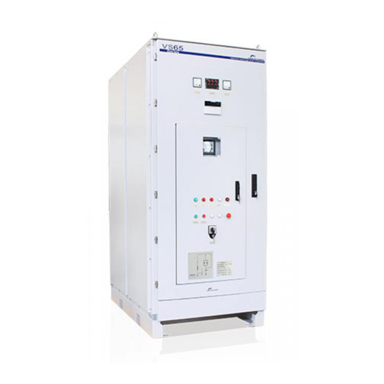
VS65 SERIES MV SOFT STARTER POWER ELECTRONICS 1. INTRODUCTION The VS65 Medium Voltage Soft starter has been designed to start, stop, protect and control medium voltage AC motors. The VS65 integrates as standard SCR stacks, Snubber circuit, trigger circuit, line and bypass vacuum contactors, fiber optics interconnections and control board, and a easy user interface, that make the VS65 MV Soft starter the most complete, reliable and safety soft starter. -
Page 14: Configuration Table
VS65 SERIES MV SOFT STARTER POWER ELECTRONICS 2. CONFIGURATION TABLE & STANDARD RATINGS 2.1. Configuration table Example of the selection table module soft starter VS65 CODE: VS6520064CLT VS65 VS65 Output Input Protection Configuration Power cable access Fuses Metal-Clad Series current... -
Page 15: Standard Ratings
VS65 SERIES MV SOFT STARTER POWER ELECTRONICS 2.2. Standard ratings MODELS VS65 2.3kV MODELS VS65 3kV – 3.3kV MOTOR POWER MOTOR POWER NOMINAL NOMINAL CODE CODE CURRENT (A) CURRENT (A) (kW) [1] (HP) (kW) [2] (HP) VS65040 2 VS65040 3... -
Page 16: Motor Power
VS65 SERIES MV SOFT STARTER POWER ELECTRONICS MODELS VS65 4.16kV MODELS VS65 6kV – 6.6kV MOTOR POWER MOTOR POWER NOMINAL NOMINAL CODE CODE CURRENT (A) CURRENT (A) (kW) (HP) [3] (kW) [4] (HP) VS65050 4 VS65040 6 VS65055 4 VS65045 6... -
Page 17: Technical Characteristics
Developed torque and power Fault history (5 last faults) Total and partial starts number Total and partial operation hours Partial motor consumption [1] For other voltages consult with Power Electronics. [2] For other configurations consult with Power Electronics. TECHNICAL CHARACTERISTICS... - Page 18 VS65 SERIES MV SOFT STARTER POWER ELECTRONICS Colour (Metal Parts) RAL 7032 Corrosion Protection C4 in accordance with ISO 12944-2 GENERAL FEATURES Painting duration H in accordance with ISO 12944-1 Input and output holes for cabling Yes, access from above...
- Page 19 VS65 SERIES MV SOFT STARTER POWER ELECTRONICS 3.1. Topology The VS65 soft starter is divided in four sections that isolate the medium voltage from the low voltage cabinets. The following image shows where the main soft starter components are placed.
-
Page 20: Operating Principles
VS65 SERIES MV SOFT STARTER POWER ELECTRONICS o Bypass vacuum contactor: After the SS starts the motor, the bypass contactor will close allowing the current flow to the motor through the bypass contactor placing the SCR in bypass. When the soft starter receives a stop command, the bypass contactor will open allowing the soft starter to make a soft motor stop. -
Page 21: Connection Diagrams
VS65 SERIES MV SOFT STARTER POWER ELECTRONICS 3.3. Connection Diagrams 3.3.1. General Power Connection Diagram Figure 3.3 General Power Connection diagram SAFETY MEDIUM VOLTAGE SWITHGEAR To compliance with IEC-62271-200 The user must connect the soft starter through a medium voltage switchgear equipped with a switch and a ground connection that permits a visible cut between the SS and the MV line. - Page 22 It will be closed after the soft starting sequence has been completed. In the case of reactive compensation capacitors connection, consult Power Electronics, the bypass relay of the VS65 SS would be installed under request. For further information consult Software and Programming manual.
- Page 23 VS65 SERIES MV SOFT STARTER POWER ELECTRONICS 4. DIMENSIONS DIMENSIONS (mm) CONFIGURATION WEIGHT (kg) HEIGHT (H) WIDTH (W) DEPTH (D) CL / C 2300 1050 1520 1100 Figure 4.1 VS65 general dimensions DIMENSIONS...
-
Page 24: Environmental Ratings
Height: Up to 1000m (For higher altitude, please contact Power Electronics.) 5.2. Reception and Storage The VS65 series soft starters are carefully tested and perfectly packed before delivering. In the event of transport damage, please ensure that you notify the transport agency and Power Electronics: 902 40 20 70 (International +34 96 136 65 57) or your nearest agent, within 24hrs from receipt of the goods. - Page 25 VS65 SERIES MV SOFT STARTER POWER ELECTRONICS Figure 5.1 VS65 Forklift truck transportation When lifting the soft starter using a crane, first gradually lift the wires until they become taugh. The use of spreaders is recommended. Lift the SS up or down slowly. At the time of placing the SS on the floor, stop lowering it just before reaching the floor and then slowly lower it on the floor to avoid any shock Figure 5.2 VS65 crane transportation...
-
Page 26: Installation Requirements
VS65 SERIES MV SOFT STARTER POWER ELECTRONICS 5.4. Installation requirements The following figure shows the safety clearance that the user must keep in the installation. It will be necessary to keep a frontal, back and upper distance at least as the one shown in the figure. The equipment can be placed one attached to another without leaving any distance between them. -
Page 27: Electrical Protections
VS65 SERIES MV SOFT STARTER POWER ELECTRONICS 6. WIRING ACCESS AND CONNECTION 6.1. Electrical Protections 6.1.1. Short circuit – Fuses (Optional) The VS65 soft starter optionally includes input protection fuses. One fuse per phase provides overcurrent protection to the equipment. The main characteristics of these fuses are shown in the next table. - Page 28 VS65 SERIES MV SOFT STARTER POWER ELECTRONICS Figure 6.2 Fuse characteristics (160A, 200A) (Source: LS System Industries Co.) 4.16kV to 6.6kV Rated Lowest Fuse Rated Power Fuse Fuse holder Rated Voltage Interrupting Interrupting Current Current Current LFL-6G-50B LFH-6G-D1HB LFL-6G-60B LFH-6G-D1HB...
-
Page 29: Ground Fault Monitoring
VS65 SERIES MV SOFT STARTER POWER ELECTRONICS Figure 6.4 Fuse characteristics (160A, 200A)-7.2kV (Source: LS System Industries Co.) Therefore, it is not recommended to install the soft starter in points where the short-circuit current available is higher than 40kA. If so, install general fuses with a greater breaking capacity and with fastest interrupting capacity. -
Page 30: Wiring Access
VS65 SERIES MV SOFT STARTER POWER ELECTRONICS 6.1.3. Contactors The VS65 SS with a rated current <400A is equipped with a line vacuum contactor and a bypass vacuum contactor, both are selected according to the rated voltage and the configuration (removable or fix). - Page 31 VS65 SERIES MV SOFT STARTER POWER ELECTRONICS The following figures describe the soft starter input and output access terminals. Figure 6.6 Power cables internal wiring The VS65 is equipped with internal wiring ducts that permit the user to route the different control, signal or data cables, without interferences.
- Page 32 VS65 SERIES MV SOFT STARTER POWER ELECTRONICS 6.3. Power and PE terminals Figure 6.8 Power terminals description Figure 6.9 Power terminals WIRING ACCESS AND CONNECTION...
-
Page 33: Wiring Recommendations
Otherwise, the equipment can be damaged and lead to injury to people. The VS65 series soft starters are built-in an earth busbar. First of all, connect the input and output shields, and the motor earth to the earth busbar of the soft starter (PE). -
Page 34: Control Terminals
VS65 SERIES MV SOFT STARTER POWER ELECTRONICS 6.5. Control Terminals The user interconnection switch (X4) is located in the frontal upper part of the locker, where the available control signs are found in accordance with the diagram attached. For other configuration, contact Power Electronics. - Page 35 VS65 SERIES MV SOFT STARTER POWER ELECTRONICS 6.5.1. Correct control shield bonding It is recommended to use shielded twisted cable for all the data, signal or control cables that came out from the soft starter, with the properly shield bounding to ground. To ensure an effective shield bundling, VS65 includes optionally EMC shield clamps that ensure a 360º...
-
Page 36: Alphanumeric Display
VS65 SERIES MV SOFT STARTER POWER ELECTRONICS 7. INTERFACE VS65 integrates multiple pushbuttons, indicators and pilots, suitable for adverse industrial environment. The interfaces are located on the top and lower front doors. 7.1. Upper door pilots and indicators Figure 7.1 Top door indicators •... -
Page 37: Control Modes
VS65 SERIES MV SOFT STARTER POWER ELECTRONICS 7.3. Lower door pushbuttons and pilots Figure 7.3 Control elements. Pilots and buttons • [CONTROL MODE] Selector Allows the user to select between the different control modes. The selector has seven positions that... - Page 38 VS65 SERIES MV SOFT STARTER POWER ELECTRONICS Down below, from left to right and up to down, the rest of the door elements are described: PUSHBUTTON / PILOT DESCRIPTION [SOFT STARTER Colour White. When no faults occur, it will turn on indicating the user that the equipment is READY] Pilot Light ready to start.
- Page 39 VS65 SERIES MV SOFT STARTER POWER ELECTRONICS 8. CONFIGURATION, LOW VOLTAGE TRIAL AND COMMISSIONING 8.1. Before Commissioning Observations • Check no foreign matter is found inside the equipment. • Verify the auxiliary power supply is 230VAC ±10%. • Verify the interconnection signs are correct and in accordance with the manual.
- Page 40 This test will be first made in the Power Electronics facilities, where the test conditions can be simulated. After, in the customer installation, it will be necessary to repeat the same test before connecting the soft starter to the medium voltage network.
- Page 41 VS65 SERIES MV SOFT STARTER POWER ELECTRONICS 8.2.2. Wiring process before the test To realize the low voltage test, these instructions should be followed: • Disconnect the medium voltage transformer cables from the primary and secondary (low and medium voltage cables). This transformer is located next to the thyristors.
- Page 42 VS65 SERIES MV SOFT STARTER POWER ELECTRONICS • 300kΩ resistor should be connected in each phase, making an electrical bridge in the medium voltage resistors, in the input of the first thyristors (terminal block JP2, terminal K) and in the phase output (terminal block JP2, terminal RF).
- Page 43 VS65 SERIES MV SOFT STARTER POWER ELECTRONICS Figure 8.6 Connection of the 300kΩ resistor in the trigger boards per phase in the medium voltage soft starters of 6000V or higher rated voltage • Connect the soft starter input to 400VAC through the terminals L1, L2 and L3.
- Page 44 VS65 SERIES MV SOFT STARTER POWER ELECTRONICS 8.2.3. Test process This process consists on two similar tests with different output components during each start. • Use the three bulbs to realize the first test. • The three-phase motor from 1 to 10CV should be connected in parallel with the three bulbs to realize the second test.
- Page 45 VS65 SERIES MV SOFT STARTER POWER ELECTRONICS 8.3. Medium voltage Commissioning Once the previous points are checked follow the next tasks. • Verify the properly connection and tightening torque of the VS65 earth terminals, both of the input and output cables shield. Ensure the minimum distance between shields and earth busbars.
-
Page 46: Preventive Maintenance
VS65 SERIES MV SOFT STARTER POWER ELECTRONICS 9. PREVENTIVE MAINTENANCE The VS65 series Medium Voltage soft starter is highly reliable and has easy maintenance. Therefore, to ensure a long working life it is recommended to take into account the following instructions: CAUTION Make sure the soft starter is completely disconnected from the power supply and earth grounded before any maintenance operation is carried out. - Page 47 VS65 SERIES MV SOFT STARTER POWER ELECTRONICS Period Inspection Instrument of Inspection Inspection method Criterion element measurement Balanced voltage between Digital Is there any imbalance Operating Measure voltage between output phases i.e. lower multimeter / between output voltage check terminals U, V and W.
-
Page 48: Declaration Of Conformity (Ce)
+34 96 136 65 57 Fax: +34 96 131 82 01 Declares under its own responsability that the product: Medium Voltage Soft Starter Brand: Power Electronics Model name: VS65 Series Is in conformity with the following European Directives: References Title 2004/108/CE Electromagnetic Compatibility... - Page 49 VS65 SERIES MV SOFT STARTER POWER ELECTRONICS ANNEX A: ELECTRIC DIAGRAMS On the following page the electric diagrams will be attached: ANNEX A: ELECTRIC DIAGRAMS...
- Page 50 No 25/4, Palaami Center, • New Natham Road (Near Ramakrishna Mutt),• 625014 • INDIA MADURAI Tel. (+91) 452 452 2125• Fax (+91) 452 452 2125 Power Electronics Italia Srl • Piazzale Cadorna, 6 • 20123 • MILANO • ITALIA ITALY Tel. (+39) 347 39 74 792 •...
- Page 51 www.power-electronics.com...
Need help?
Do you have a question about the VS65 Series and is the answer not in the manual?
Questions and answers