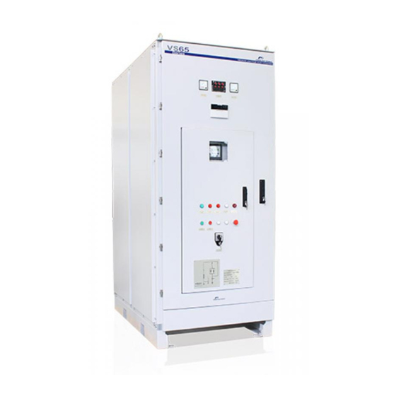
Power Electronics VS65 Series Getting Started
Medium voltage softstarter
Hide thumbs
Also See for VS65 Series:
- Programming and software manual (48 pages) ,
- Hardware and installation manual (52 pages)
Table of Contents
Advertisement
Advertisement
Table of Contents

Related Manuals for Power Electronics VS65 Series


Summary of Contents for Power Electronics VS65 Series
- Page 1 MEDIUM VOLTAGE SOFTSTARTER G e t t i n g St a r t e d M a n u a l...
- Page 3 medium voltage soft starter Getting Started Manual Edition: November 2008 VS65IM01AI Rev. A...
- Page 4 POWER ELECTRONICS VS65...
- Page 5 POWER ELECTRONICS VS65 SAFETY SYMBOLS Always follow safety instructions to prevent accidents and potential hazards from occurring. This symbol means improper operation may results in serious personal WARNING injury or death. Identifies shock hazards under certain conditions. Particular attention should be given because dangerous voltage may be present.
- Page 6 POWER ELECTRONICS VS65 Revisions Date Revision Description 30 / 11 / 2008 First edition...
-
Page 7: Table Of Contents
POWER ELECTRONICS VS65 INDEX SAFETY INSTRUCTIONS ......................INTRODUCTION ........................1.1. Overview ........................1.2. Technical Indicators and Performance............... 1.3. Design Features......................1.4. Operating Principle..................... 1.5. Protection for Motor and System................INSTALLATION AND CONNECTION.................. 2.1. Acceptance and Unpacking ..................2.2. Initial Inspection ...................... - Page 8 POWER ELECTRONICS VS65 INDEX...
-
Page 9: Safety Instructions
POWER ELECTRONICS VS65 SAFETY INSTRUCTIONS IMPORTANT! Read this manual carefully to maximise the performance of this product and to ensure its safe use. In this manual, safety messages are classified as follows: WARNING Do not remove the cover while the power is applied or the unit is in operation. - Page 10 In the even of transport damage, please ensure that you notify the transport agency and POWER ELECTRONICS: 902 40 20 70 (International +34 96 136 65 57) or your nearest agent, within 24hrs from receipt of the goods.
- Page 11 POWER ELECTRONICS VS65 PRECAUTIONS Electric shock prevention: The enclosure of the starter cabinet must be grounded properly to keep away from the electric shock even if electric leakage on the enclosure. Disconnect all power supplies before maintenance for soft starter or motor. Due to storage function of internal RC circuit, the triggering component will keep dangerous voltage even if the main power supply is cut off.
- Page 12 POWER ELECTRONICS VS65 SAFETY INSTRUCTIONS...
-
Page 13: Introduction
POWER ELECTRONICS VS65 1. INTRODUCTION This chapter will introduce the VS65 Medium and High voltage solid starter series, describing their appearance, functions and operations. We recommend that new users read this chapter and acquire an overall understanding before operating the soft starter. -
Page 14: Design Features
POWER ELECTRONICS VS65 Up to 5 control modes: 0: Keyboard 1: Remote control CONTROL 2: Keyboard + Remote control MODES 3: PC 4: Keyboard + PC 5: Remote control + PC Over voltage (trip or alarm programmable) Low voltage (trip or alarm programmable) -
Page 15: Operating Principle
Meanwhile, it also can reduce the mechanical impact to the device, increasing the equipment’s service life and avoid some fault and breakdown. VS65 series can provide 3 types of starting mode: Voltage ramp starting mode: The voltage ramp with current-limiting function is the factory configuration and the most reliable starting mode that meets the most requirements. -
Page 16: Protection For Motor And System
POWER ELECTRONICS VS65 Heavy load starting mode: The mode is used mainly in some applications where the motor drives the loads with big inertia such as the fan, the ball mills, etc. The function can increase 8 seconds to alternative the bypass circuit in order to avoid excessively impact current due to too earlier switching. - Page 17 POWER ELECTRONICS VS65 Quickly current break (by the main circuit-breaker of MV power supply) Over current protection, phase imbalance protection, and lock rotor protection Low voltage & over voltage protection Over temperature protection of the motor, realized through the motor thermal mode or electrical measurement.
-
Page 18: Installation And Connection
POWER ELECTRONICS VS65 2. INSTALLATION AND CONNECTION 2.1. Acceptance and Unpacking VS65 is usually transported upright. For the shipment abroad, the equipment may be placed horizontally in a container. Unpack the goods carefully and check for any damage taken placed during the transportation. In case of damaged, please fill in a damage report within 15 days of reception of delivery order. -
Page 19: Control Terminals Description
POWER ELECTRONICS VS65 2.5. Control Terminals Description Descriptions about the terminals on the Control board and the power supply. SIGNAL DESCRIPTION AC power input terminal To 3-phase AC power supply via module case circuit-breaker (MCCB). MAIN LOOP Soft starter’s output To 3-phase asynchronous motor. -
Page 20: Connection And Usage Of Control Terminals
POWER ELECTRONICS VS65 2.6. Connection and Usage of Control Terminals 2.6.1. Preparations for connection If the user intends to use the external terminals, we suggest using a shielded wire leading out from the terminal, the shielded should be connected to the ground. - Page 21 POWER ELECTRONICS VS65 Figure 2.2 J2 Connector wiring But the two-wire connection should be practiced for the cases below (See Fig 2.3). When the customer needs only a switching contact to control starting and stop of softstarter, like the control contact J of PC/PLC.
-
Page 22: Standard Ratings
POWER ELECTRONICS VS65 3. STANDARD RATINGS 3.1. Designation Code EXAMPLE CODE: VS6520064 VS65 VS65 Output Input Protection Series Current Voltage Degree 200A 2300V IP4X 250A 3300V 4160V 6600V 10000V – 15000V STANDARD RATINGS... -
Page 23: Table Of Standard Ratings
VS6580010X 11760 Customized Customized Customized Notes: 1. To indicate the Protection Degree, replace X by the first number of it (for example: Replace X by 4 for IP40). 2. For different voltages and currents, contact with Power Electronics. STANDARD RATINGS... -
Page 24: Programming Keyboard
POWER ELECTRONICS VS65 4. PROGRAMMING KEYBOARD 4.1. Display and Keyboard LCD is the display device, which is divided into text and character display zones. The text zone shows various parameters value and the character area indicates status of the softstarter. -
Page 25: Function Codes Explanations
POWER ELECTRONICS VS65 Code Name Range Default Description Function Interlock control 0: delay See 4.3.6 0: Current limiting 1:Voltage Starting mode 2: Heavy load 0:Keypad 1: Remote Control mode 2:Keypad + remote 3:PC 4:Keypad + PC 5:Remote +PC Analogue current... - Page 26 POWER ELECTRONICS VS65 4.3.2. Code 02 – Shutdown time The shutdown time of 0 second means the free stopping. Excessive shutdown time maybe cause the system is instable. (See Figure 4.3). Figure 4.3 Stop mode 4.3.3. Code 03 – Starting delay This is the duration from the moment while the remote startup is closed (two-wire type) until the softstarter begins running.
- Page 27 POWER ELECTRONICS VS65 4.3.5. Code 05 – Emergency stop setup By setting the code 0 or 1, the user can turn on or turn off the remote emergency input. Setting 0 is disabled, setting 1 is enabled. 4.3.6. Code 06 – Interlocking delay. Code 07 – Interlocking control The starter’s interlocking output is controlled by programming these two values.
- Page 28 POWER ELECTRONICS VS65 4.3.9. Code 10 – Current signal selection Measure the proportional current signal according to the load. Four options are available, as shown in following table. Set Value Output current mA 0 – 10 0 – 10 4 – 10 4 –...
- Page 29 POWER ELECTRONICS VS65 4.3.16. Code 17 – Even-odd check This is used for selection of check method by MODBUS communication. It should be in accordance with the master device. 4.3.17. Code 18 – Bbus mode This is used in PROFIBUS, with 0 for Method 1 where parameters modification is allowed and 1 for Method 2, where only starter monitoring is performed.
-
Page 30: How To Program
POWER ELECTRONICS VS65 4.4. How to program 4.4.1. Programming flow chart Figure 4.5 Block diagram for programming Note: Once data is written, it will be kept till it is modified at next time. Power loss will not erase the written data. - Page 31 POWER ELECTRONICS VS65 Press and hold “Λ“ key till the 300% indicated value reaches 300% Current limiting multiple Press ”PRGM” key 300% Data writing 4.4.3. How to input default values If a fault of parameter occurs, it is necessary to input factory (default) value.
-
Page 32: Powering On And Running
POWER ELECTRONICS VS65 5. POWERING ON AND RUNNING 5.1. Low-Voltage Trial Run It is necessary that the starter have to be running at a low-voltage test firstly, in order to ensure it can be running normally while the medium voltage input. This test is done at manufacturer installations where corresponding test conditions can be considered. -
Page 33: High-Voltage Trial Run
POWER ELECTRONICS VS65 5.2. High-Voltage Trial Run Set up connections for the main loop according to 2.4. Since the soft starter’s incoming lines do not have section breakers, it is necessary to power on the cabinet by using the main circuit-breaker on the incoming cabinet. -
Page 34: Fault Messages. Descriptions And Actions
POWER ELECTRONICS VS65 6. FAULT MESSAGES. DESCRIPTIONS AND ACTIONS The VS65 soft starter have the comprehensive protection function, it can stop in case of any fault, display and save the fault codes. The fault status only can be reset by using the STOP (RST) key (* if using the fault reset automatically, it will be starting automatically, please be carefully to ensure the safety) Figure 6.1 Fault display... -
Page 35: Fault History
POWER ELECTRONICS VS65 6.2. Fault History The soft starter can save up to 5 faults history for analysis in future. 6.2.1. Display the saved fault When the starter is in the ready status (or fault status), press “PRGM” for more than 4 seconds. -
Page 36: Communication Protocol
POWER ELECTRONICS VS65 7. COMMUNICATION PROTOCOL The customer can select the protocol between Modbus and Profibus when placing orders. In case of choosing communication bus controlling, the function code 09 must be set to 04, 05, or 06 to activate the communication function. - Page 37 POWER ELECTRONICS VS65 7.1.2. Parameter explanation When PPO1 is chosen, function parameters of VS65 can be read and modified. The high byte (INDH) of parameter index (word) IND is task request, the low byte (INDL) is parameter address, which corresponds to the address of function code. PWE is the value of visited parameter. All values are the hexadecimal.
- Page 38 POWER ELECTRONICS VS65 7.1.4. PZD (process control) explanation The PZD area is to control and test the soft starter. PZD1 PZD2 MASTER – VS65 ---- STW control word is used to start, stop and fault reset of soft starter. Name...
- Page 39 POWER ELECTRONICS VS65 PZD examples Example 1: Start the starter MASTER VS65 0B 00 VS65 MASTER This means the starting status, with current value of 240%. Example 2: Stop the starter MASTER VS65 0A 00 VS65 MASTER 0C 00 This means the stopping status, with current value of 240%.
-
Page 40: Modbus Protocol
POWER ELECTRONICS VS65 7.2. Modbus Protocol This section will explain how to control various operations of VS65 through Modbus communication. 7.2.1. Overview about Modbus Modbus is a serial asynchronous communication protocol, with physical interface of RS485. Modbus protocol is designed for modicon PLC, has structural features of PLC. The VS65 soft starter can be read and write in the Modbus network. - Page 41 POWER ELECTRONICS VS65 7.2.3. Register Information 40001 command register Value Description Starter starting Hold mode Starter shutdown Hold mode 0 – 1 Reset starter 3 – 15 Unused Example: To start the softstarter with the slave address 02. The controller sends 02 06 00 00 00 01.
- Page 42 POWER ELECTRONICS VS65 Function parameter register 40XXX of soft starter XXX-1 is as 1YY in hexadecimal and YY corresponds to code value in table on section 4.2. For example, 108 corresponds with 08 (starting mode). Reading or writing these function codes is possible.
-
Page 43: Annexe A. Power Cabinet Operation
POWER ELECTRONICS VS65 8. ANNEXE A. POWER CABINET OPERATION There are several components on the front panel of the power cabinet to control the power-on process of this cabinet. See the following figure. Figure 8.1 Control panel of Power cabinet... -
Page 44: Switch Operation Of Power Cabinet
POWER ELECTRONICS VS65 8.1. Switch Operation of Power Cabinet The next steps must be followed in order to power-on the power cabinet: 1. Moving the MV breaker from the test position to the working position by the rotating Rocker. You can hear a “click” sound while the MV breaker is on the working position, after power up you can find the “MV breaker in working position”... - Page 45 POWER ELECTRONICS VS65 Multi-function Visualization Parameters Setting of Multi-function Visualization. Nº Parameter Description Value Remark In.Pt Voltage ratio Fixed value In.Ct Current ratio Fixed value In.U Secondary Voltage 100V Fixed value In.I Secondary Current Fixed value Note: The value is only for reference...
- Page 46 POWER ELECTRONICS VS65 4. Interlocking function o Interlocking between the local operation and the remote operation. 5. Communication function o CAN bus and the standard RS485 communication port. 6. Characteristic o Modular design, it can be assembled or integrated into the switch board.
- Page 47 POWER ELECTRONICS VS65 Figure 8.5 Logic diagram of NPS II protection Overload protection If the current of phase A or phase C (or three phases) is larger than overload setting value, then the timer is starting. The device can select the action between the warn and trip.
- Page 48 POWER ELECTRONICS VS65 Residual over voltage protection The residual over voltage protection is also used to prevent the stator from the earth fault. If the zero sequence voltage is larger than the setting value, then the timer is starting. The device can select the action between the warn and trip.
- Page 49 POWER ELECTRONICS VS65 PT breaking protection The device can detect the PT breaking status. If meet any conditions as below, the device will send out the warning signal after 10 seconds. The max. phase voltage is less than 30V and any phase current is larger than 0.3 A The negative sequence voltage is larger than 8V.
- Page 50 POWER ELECTRONICS VS65 Record (SOE) The device can store more than 60 event records, including date, time, fault current, fault voltage, the protecting action. You can upload them to the supervision system by the communication. Fault recorder Record the waveform of current and voltage at fault moment.
- Page 51 POWER ELECTRONICS VS65 01 Pro ON OFF Put the cursor at “Pro ON OFF” and press the “enter” key, then come into the protection function enable or disable setting as below: (e.g. Line protection) OCInst RLP01 OCInst Dir RLP02 Put the cursor at “ON/OFF” setting of “OCInst”, you can select the protection items by the key “↑”, “↓”, then you can change the setting by the key “←”,”→”.
- Page 52 POWER ELECTRONICS VS65 Remark: the No.0000 is event number, 02-06-26 is the date when the event occurred, that corresponds to year–month–day.11:21:22.525 is corresponding to hour-minute-second- millisecond. By the “↑”, “↓” to display all events. If the type of event is protection operation, press “enter” to check the operation value, and then press the key “Ext”...
- Page 53 POWER ELECTRONICS VS65 06 Time The device has a real-time clock that can be running after power off, after entering into the “Time” submenu and then the display as below: Date Time You can regulate the real clock by the keypad. Press the “enter” key to enter into an editing status.
- Page 54 POWER ELECTRONICS VS65 8.2.1.3. Miscellaneous Tables Real time display of sampling Real time display of sampling Channel 00 Measure current Ia (C7, D7) Channel 05 Protection current Ia (C9, D9) Channel 01 Measure current Ic (C8, D8) Channel 06 Protection current Ib (C10, D10)
- Page 55 POWER ELECTRONICS VS65 Pro ON OFF Nº Code Parameter Description RLP01 OCDTI Over current I protection RLP02 OCDTII Over current II protection Negative phase sequence over current I RLP03 NPS I protection Negative phase sequence over current II RLP04 NPS II...
-
Page 56: Annexe B. Electrical And Mechanical Drawings
POWER ELECTRONICS VS65 9. ANNEXE B. ELECTRICAL AND MECHANICAL DRAWINGS Next, electrical and mechanical drawings are attached in the following pages. ANNEXE B. ELECTRICAL AND MECHANICAL DRAWINGS... - Page 71 Tel. (+34) 96 136 65 57 · Fax. (+34) 96 131 82 01 INTERNATIONAL BRANCHES: Power Electronics Australia Pty Ltd AUSTRALIA U6, 30-34 Octal St, Yatala, Brisbane, Queensland 4207 · P.O. Box 3166 Browns Plains · Queensland 4118 · AUSTRALIA Tel.
Need help?
Do you have a question about the VS65 Series and is the answer not in the manual?
Questions and answers