
Subscribe to Our Youtube Channel
Related Manuals for 3nStar 2054K Series


Summary of Contents for 3nStar 2054K Series
- Page 1 XP-DT325B 2054K Series Thermal Barcode Printer User’s Manual Please keep the user’s manual properly for reference...
-
Page 2: Table Of Contents
Contents Copyright statement......................1 Cautions..........................1 I. Product..........................2 II. Receiving........................3 2.1 Unpacking and checking accessories..............4 2.2 Printer components....................5 2.2.1 Front view.....................5 2.2.2 Rear view......................5 III. Installation........................6 3.1 Install the printer.....................6 3.2 Install the label......................7 3.3 Install the stripping module – optional..............8 3.4 Stripping mode –... -
Page 3: Copyright Statement
Copyright statement The manual is provided to the purchaser for reference in use and operation of the purchased equipment, and shall not be used or copied for other purposes without express written permission. All other brand names, product names, or trademarks are the property of other individual owners. -
Page 4: Product
your body away from the paper exit to avoid crushing injury. 2. If the button battery RTC contained in the main board is not replaced correctly, the main board cannot be used normally. 3. Please dispose of the used batteries according to the manufacturer’s operation instructions. -
Page 5: Receiving
the volume labels can be printed in a wide range of texts or graphic formats. Meanwhile, its superior function and easy operation make it your best choice among the thermal barcode printers of the same level. series printer provides thermal printing. The printing speed is adjustable 2054K from 2.0, 3.0, 4.0, 5.0 to 6.0 inches per second. -
Page 6: Unpacking And Checking Accessories
transportation, you are kindly required to check the packaging and all units carefully when receiving the printer. In case of obvious damage, please contact the sales dealer directly and indicate the severity of the damage. If necessary, you should keep the packaging materials for returning the printer. -
Page 7: Printer Components
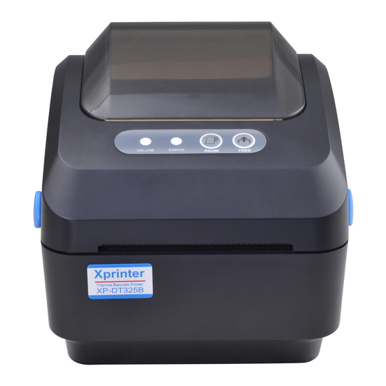
2.2 Printer components 2.2.1 Front view Transparent window Feed button Printer cover Power indicator Paper exit Cover hook Front panel 2.2.2 Rear view 1. Power switch 2. Power socket 3. USB interface 4. Ethernet interface 5. SD card slot 2 3 4 Note: The transmission interfaces of the printer in the picture will vary depending on the model of machine you purchase. -
Page 8: Installation
III. Installation 3.1 Install the printer 1. Place the printer on a smooth and steady surface and make sure the power is off. 2. Plug one end of the parallel port cable, serial port cable or USB cable into the slot on the back of the printer, and connect the other end of the cable to the appropriate slot of your computer. -
Page 9: Install The Label
3.2 Install the label 1. Install the label into the paper supply kit. (Fixing plate & Paper roll shaft ) Paper roll Fixing plate *1.5"纸卷轴榇套 纸卷 Fixing plate 固定片 打印面朝上 Print side up 纸卷轴 1" Paper roll shaft 2. Push the printer cover hook forward with both hands to open the printer cover. 3. -
Page 10: Install The Stripping Module - Optional
5. Close the printer cover. Note: To avoid poor printing quality, make sure the printer cover is closed tightly. 3.3 Install the peel-off module – optional 1. Push the cover hook forward with both hands to open the upper cover of the printer. 2. -
Page 11: Stripping Mode - Optional
3.4 Install the label with peel-off module 1. Pull the paper stripper apart. Peel-off roller front panel 2. Pass the label through the paper guide, and pull the label over the rubber roller. 3. Pass the label through the backing paper exit under the roller (as shown by the blue dotted line below). -
Page 12: Install The Cutter - Optional
5. Close the front panel. 6. Put on the upper cover of the printer. 3.5 Install the cutter – optional 1. Push the cover release button forward with both hands to open the upper cover of the printer. 2. Insert the cutter cable into the corresponding socket hole. 3. -
Page 13: Led Indicator
conjunction with different colors or collaborating with the power switch will enable the printer to start multiple functions, such as feeding paper, pausing the printer, calibrating the label sensor, printing the self-test value, and initializing the printer. Details are described as follows: 4.1 LED indicator LED indicator color Description... - Page 14 restores it to the factory default value, the label paper gap sensor needs to be re-measured. The gap detection or black line mark calibration will be completed with your last set value as the reference value. The default value of this printer sensor is set to gap calibration. Please follow the steps below to calibrate the ribbon and gap/black mark sensor: 1.
- Page 15 and know the internal settings of the printer. Internal settings of printer printed in the self-test mode Print head check sample Model & firmware version Machine serial number Print head mileage Check code Serial port setting Character set Country code Printing speed Printing density Paper size (width, height)
- Page 16 Hexadecimal value ASCII string data corresponding to the ASCII string listed on the left Note: 4" Label paper of wide is required to print all the debugging mode data. Restart the printer to leave the debugging mode and return to the normal printing mode, or press the FEED button to return to the standby state.
- Page 17 Please follow the steps below to complete the initialization: 1. Turn off the power. 2. Hold down the feed button and turn on the power. At this point, the power indicator color will cycle as follows: Indicator color cycle mode: Purple Blue Red (blink 5 times)
-
Page 18: Diagnostic Tool
Please follow the steps below to skip AUTO.BAS: 1. Turn off the power. Hold down the feed button and turn on the power. At this point, the power indicator color will cycle as follows: Indicator color cycle mode: Purple Blue Red (blink 5 times) Purple (blink 5 times) Blue (blink 5 times) -
Page 19: Enable The Diagnostic Tool Program
5.1 Enable the Diagnostic Tool program 1. Move the mouse cursor to the Diagnostic Tool image and double click the left mouse button. 2. After it is started, the main screen shows 4 management pages (printer settings, file management, communication tools, system printer settings). 5.2 Printer settings 1. -
Page 20: Calibrate The Paper Sensor With The Diagnostic Tool
The default communication interface of the Diagnostic Tool program is USB, so if the computer is connected through USB cable for transmission, no changes need to be made to the settings. 2. Click on a function you intend to set in the "Printer Settings". 3. -
Page 21: Set The Ethernet With The Diagnostic Tool (Optional)
5.4 Set the Ethernet with the Diagnostic Tool (optional) The Diagnostic Tool program is attached to the Utilities folder in the CD provided with the printer. The user can use the Diagnostic Tool to set up via USB, RS-232 or Ethernet interface through Ethernet. - Page 22 The factory default value set by such IP is “Automatically obtain the IP location”. If you need to change your IP location, please select “Designate the IP location” and enter the IP, subnet mask and gateway to be set, and then press the “Set IP” button to set, and the user can also change the name of the printer by pressing the “Set printer name”...
-
Page 23: Troubleshooting
VI. Troubleshooting 6.1 Common problems The table below shows the common problems the printer operators normally meet and the solutions to them; if you have tried the troubleshooting in the ways we suggest but the printer is still not working properly, please contact the customer service of the vendor for more assistance. - The power indicator is off. - Page 24 Problem Possible cause Solution * Reconnect the transmission line * If you are using a serial port cable, - Replace the serial port cable. The pin of the cable must be of 1 to 1 type - Make sure that the transmission rate of the printer is set to 9600, n,8,1 * If you are using an Ethernet cable, - Make sure that the Ethernet RJ-45 blue/purple...
- Page 25 Problem Possible cause Solution * The microSD memory * Use a microSD memory card with card is damaged supporting capacity - The microSD * The microSD memory * Re-insert the microSD memory card memory card is not card is not inserted correctly available * The microSD card is from unverified manufacturer...
- Page 26 Problem Possible cause Solution * The label sensor setting is * Recalibrate the label sensor incorrect * Set the correct volume label size and * The label size setting is volume label gap size incorrect * If the BarTender software is used, set * The vertical offset setting the vertical offset in the printer driver of the volume label style in...
-
Page 27: Simple Maintenance Procedures Of The Printer
VII. Simple maintenance procedures of the printer The simple maintenance procedures aim to ensure the printing quality and extend the life of the printer. Below are some of our recommended maintenance procedures. 1. Clean and maintain your printer by using the tools listed below: Cotton swab ... -
Page 28: Update History
case, user may need to take practical measures accordingly Update history Date Content Editor August 12, 2019 First issue Hu Xiang...
Need help?
Do you have a question about the 2054K Series and is the answer not in the manual?
Questions and answers