
Subscribe to Our Youtube Channel
Related Manuals for CYP CPLUS-V4H2HP-DT


Summary of Contents for CYP CPLUS-V4H2HP-DT
- Page 1 CPLUS-V4H2HP-DT 4×2 HDMI Matrix with Dante Audio Operation Manual Operation Manual...
- Page 2 ® registered trademarks of HDMI licensing Administrator, Inc.
- Page 3 DISCLAIMERS The information in this manual has been carefully checked and is believed to be accurate. Cypress Technology assumes no responsibility for any infringements of patents or other rights of third parties which may result from its use. Cypress Technology assumes no responsibility for any inaccuracies that may be contained in this document.
- Page 4 SAFETY PRECAUTIONS Please read all instructions before attempting to unpack, install or operate this equipment and before connecting the power supply. Please keep the following in mind as you unpack and install this equipment: • Always follow basic safety precautions to reduce the risk of fire, electrical shock and injury to persons.
-
Page 5: Table Of Contents
CONTENTS 1. Introduction ............1 2. Applications ............. 1 3. Package Contents ........... 1 4. System Requirements ........2 5. Features............2 6. Operation Controls and Functions ....3 6.1 Front Panel ..........3 6.2 Rear Panel........... 4 6.3 RS-232 Pinout and Defaults ......5 6.4 WebGUI Control .......... -
Page 6: Introduction
1. INTRODUCTION This 4 by 2 HDMI Matrix with Dante Audio is a high performance HDMI switch which provides 4K UHD (18Gbps) HDMI matrix routing and integrated Dante/AES67 network audio routing, insertion, and extraction. It is an ideal solution for switching between multiple sources in a control room, conference room or classroom while simultaneously providing and receiving high quality digital stereo audio via the connected network. -
Page 7: System Requirements
4. SYSTEM REQUIREMENTS • HDMI source equipment such as media players, video game consoles, PCs, or set-top boxes. • HDMI receiving equipment such as HDTVs, monitors or audio amplifiers. • Analog audio receiving equipment such as audio amplifiers or powered speakers. -
Page 8: Operation Controls And Functions
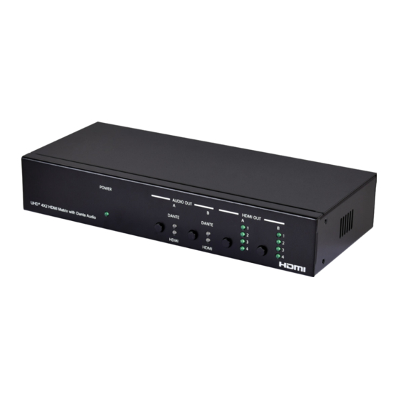
6. OPERATION CONTROLS AND FUNCTIONS 6.1 Front Panel AUDIO OUT HDMI OUT POWER DANTE DANTE UHD + 4X2 HDMI Matrix with Dante Audio HDMI HDMI POWER LED: This LED will illuminate to indicate the unit is on and receiving power. AUDIO OUT A Button &... -
Page 9: Rear Panel
6.2 Rear Panel AUDIO OUT A AUDIO OUT B L+ L- G R+ R- L+ L- G R+ R- DC 5V HDMI IN HDMI OUT TX RX RS-232 SERVICE CONTROL HDMI IN 1~4 Port: Connect to HDMI source equipment such as media players, game consoles, or set-top boxes. -
Page 10: Rs-232 Pinout And Defaults
6.3 RS-232 Pinout and Defaults Serial Port Default Settings Baud Rate 19200 Data Bits Parity Bits None Stop Bits Flow Control None 3-pin Terminal Block... -
Page 11: Webgui Control
6.4 WebGUI Control • Device Discovery Please obtain the “Device Discovery” software from your authorized dealer and save it in a directory where you can easily find it. Connect the unit and your PC/Laptop to the same active network and execute the “Device Discovery”... - Page 12 • WebGUI Overview After connecting to the WebGUI’s address in a web browser, the login screen will appear. Please enter the appropriate user name and password then click “Submit” to log in. Note: The default user name and password is “admin”. On the left side of the browser you will see the following menu tabs where all primary functions of the unit are controllable via the built in WebGUI.
-
Page 13: Video Switch Tab
6.4.1 Video Switch Tab This tab provides video routing control, HDCP management, and I/O renaming options. To assign a new video route, select one or both output buttons on the left and then click on the button of the preferred input source on the right. - Page 14 4) Input Edit: Provides individual control over the name of each input as well as the behavior of HDCP on that input. „ Set Input Name: To rename an input, type the new name in the space provided in the edit window then click the “Save” button to confirm the change.
-
Page 15: Audio Switch Tab
6.4.2 Audio Switch Tab This tab provides audio routing control, analog audio volume control and muting, I/O renaming options, and basic Dante network audio management. To assign a new audio route configuration, select one or both output buttons on the left and then click on either the “Follow Video” or “Follow Dante” button on the right. - Page 16 2) Input: Buttons for selecting the input type (“Follow Video” or “Follow Dante”) to assign to each audio output as well as dedicated Dante audio source buttons to be used when “Follow Dante” has been selected for an output. „ Follow Video: Selecting this as the audio input type for an output will cause the output to use the bypass audio from the currently routed video source.
- Page 17 assigned device name, default device name, Rx and Tx channel names, MAC address, master MAC address, IP address, IP mode, and IP speed. 3) Audio Output Edit: Provides control over the name of the audio output and volume level of the analog audio output. „...
-
Page 18: Edid Tab
6.4.3 EDID Tab This tab provides control over the EDID settings for all inputs. This unit provides the option of six standard EDIDs, two sink sourced EDIDs and four user uploaded EDIDs that can be assigned to one input or all inputs as a group. - Page 19 2) Output EDID: „ Download: To save the EDID from a connected display to your local PC, select the sink from the dropdown list then press the “Download” button. Depending on your browser settings you will either be asked where to save the downloaded file, or the file will be transferred directly to the default download location on your PC.
-
Page 20: Network Tab
6.4.4 Network Tab This tab provides network configuration options including changing the IP mode, viewing/setting the IP configuration, changing the admin login password, and changing the Web Login timeout. Note: The default IP address is 192.168.1.50. 1) IP Configuration: IP Mode may be switched between Static IP or DHCP. -
Page 21: System Tab
6.4.5 System Tab This tab provides system configuration backup/restore options, controls to perform a factory reset or system reboot, firmware update support, and the unit’s serial number. 1) System Configuration: „ Download: The current system configuration, including routing and settings, may be saved as an XML file to a PC. Click the “Download” button to save the current system configuration to your local PC. -
Page 22: Telnet Control
6.5 Telnet Control Before attempting to use Telnet control, please ensure that both the unit and the PC are connected to the same active networks. Start your preferred Telnet/Console client, or use the built in client provided by most modern computer operating systems. After starting the client, connect by using the current IP address of the unit and port 23 (if the communication port number used by the unit has not been changed previously). - Page 23 COMMAND Description and Parameters get command ver Show the unit’s current command version. get mac addr Show the unit’s MAC address. get model name Show the unit’s model name. get model type Show the unit’s product type. Possible response values: [Matrix] [Scaler] [Splitter]...
- Page 24 COMMAND Description and Parameters get feedback broadcast Show the current console command feedback broadcast state. set local echo N1 Enable or disable the local echo display of typed characters for RS-232 connections. Available values for N1: [Enable] [Disable] get local echo Show the current local echo display setting.
- Page 25 COMMAND Description and Parameters get uart 1 baudrate Show the current baud rate of the RS-232 port. set uart 1 stop bit N1 Set the number of stop bits for the RS-232 port. Available values for N1: [1 Stop Bit] [2 Stop Bits] get uart 1 stop bit...
- Page 26 COMMAND Description and Parameters get ip mode Show the current IP address assignment mode. get ipconfig Show the unit’s current IP configuration information get ip addr Show the unit’s current IP address. get netmask Show the unit’s current netmask. get gateway Show the unit’s current gateway address.
- Page 27 COMMAND Description and Parameters get webgui username Show the WebGUI login username. Note: Only available via RS-232. set webgui password N1 Set the WebGUI administrator password. N1 = {Password} [ASCII, 32 characters max] Note: Only available via RS-232. get webgui password Show the current WebGUI administrator password.
- Page 28 COMMAND Description and Parameters set telnet login N1 Enable or disable requiring a login for Telnet connections. Available values for N1: [Login is required] [Login is not required] Note: Only available via RS-232. get telnet login Show the current state of the Telnet login requirement. Note: Only available via RS-232.
- Page 29 COMMAND Description and Parameters set out N1 name N2 Set the name of the specified output. Available values for N1: [HDMI output A] [HDMI output B] N2 = {Name} [ASCII, 32 characters max] get out N1 name Show the name of the specified output. Available values for N1: [HDMI output A] [HDMI output B]...
- Page 30 COMMAND Description and Parameters get in N1 hactive Show the horizontal active pixel value of the specified input’s current video source. Available values for N1: [HDMI input 1] [HDMI input 2] [HDMI input 3] [HDMI input 4] get in N1 vactive Show the vertical active pixel value of the specified input’s current video source.
- Page 31 COMMAND Description and Parameters get in N1 sync status Show the current sync state of the specified input. Available values for N1: [HDMI input 1] [HDMI input 2] [HDMI input 3] [HDMI input 4] Possible response values: [No sync] [Sync active] get out N1 sync status...
- Page 32 COMMAND Description and Parameters get in N1 hdcp mode Show the current HDCP behavior used by the specified input. Available values for N1: [HDMI input 1] [HDMI input 2] [HDMI input 3] [HDMI input 4] get in N1 hdcp status Show the current HDCP status of the specified input.
- Page 33 COMMAND Description and Parameters set in N1 edid N2 Set the EDID to use on the specified input. Available values for N1: [HDMI Input 1] [HDMI input 2] [HDMI Input 3] [HDMI Input 4] Available values for N2: [FHD 2CH] [FHD MCH] [UHD 2CH] [UHD MCH]...
- Page 34 COMMAND Description and Parameters set edid N1 name N2 Set the name for the specified EDID. (Only User EDIDs may be renamed) Available values for N1: [User EDID 1] [User EDID 2] [User EDID 3] [User EDID 4] N2 = {Name} [ASCII, 32 characters max] get edid N1 name...
- Page 35 COMMAND Description and Parameters get user N1 edid data Show the current contents of the specified User EDID as hex data. Available values for N1: [User EDID 1] [User EDID 2] [User EDID 3] [User EDID 4] get sink N1 edid data Show the EDID from the display connected to the specified output as hex data.
- Page 36 COMMAND Description and Parameters set all in edid mode N1 Select the EDID management mode to use (All or Appoint) for all inputs. Available values for N1: [All] [Appoint] get all in edid mode Show the current EDID management mode used by all inputs. set all in edid N1...
- Page 37 COMMAND Description and Parameters get audio out N1 mute Show the current mute state of the specified output. Available values for N1: [Analog audio output A] [Analog audio output B] set audio out all mute N1 Enable or disable muting on all analog audio outputs. Available values for N1: [Mute] [Unmute]...
- Page 38 COMMAND Description and Parameters set audio out N1 volume N2 Set the volume level of the specified output’s audio. Available values for N1: [Analog audio output A] [Analog audio output B] N2 = 0~100 [Audio volume level in dB] get audio out N1 volume Show the current volume level of the specified output’s audio.
- Page 39 COMMAND Description and Parameters get audio out N1 name Show the current name for the specified output’s audio. Available values for N1: [Audio output A] [Audio output B] set dante friendly name N1 Set this unit’s Dante device friendly network name. N1 = {Dante Name} [ASCII, 31 characters max] Note: Dante device names must consist of standard alpha-numeric...
- Page 40 COMMAND Description and Parameters set dante rx N1 route N2@N3 Route the specified remote Dante audio channel at the specified Dante device to the specified local Dante Rx channel. N1 = 1~4 [Local Dante Rx channel number] N2 = {Channel Name} [Remote Dante channel name] N3 = {Dante Name} [Remote Dante device friendly name] get dante rx N1 route...
- Page 41 COMMAND Description and Parameters set dante discover Trigger the discovery of all available Dante devices on the local network. Note: Only compatible Dante sources from the same manufacturer will be detected. Up to 4 additional Dante sources can be detected. get dante N1 config...
- Page 42 COMMAND Description and Parameters set dante static ipaddr N1 Set the static IP address for the unit’s Dante network port. N1 = X.X.X.X [X = 0~255, IP address] get dante static ipaddr Show the current static IP address of the unit’s Dante network port. set dante static netmask N1...
-
Page 43: Connection Diagram
7. CONNECTION DIAGRAM Powered Speakers Media Player HDMI Input Powered Speakers Game Console Power Supply AUDIO OUT A AUDIO OUT B L+ L- G R+ R- L+ L- G R+ R- DC 5V HDMI IN HDMI OUT TX RX RS-232 SERVICE CONTROL HDMI Input... -
Page 44: Specifications
8. SPECIFICATIONS 8.1 Technical Specifications HDMI Bandwidth 18Gbps Dante Bandwidth 100Mbps Input Ports 4×HDMI (Type-A) Output Ports 2×HDMI (Type-A) 2×Stereo Audio (5-pin Terminal Block) Bi-directional Port 1×Dante (RJ-45) Control Ports 1×RS-232 (3-pin Terminal Block) 1×IP Control (RJ-45) Service Port 1×USB 2.0 (Type-A) Baud Rate 19200 Power Supply... -
Page 45: Video Specifications
8.2 Video Specifications Input Output Supported Resolutions (Hz) HDMI HDMI 720×400p@70/85 640×480p@60/72/75/85 720×480i@60 720×480p@60 720×576i@50 720×576p@50 800×600p@56/60/72/75/85 848×480p@60 1024×768p@60/70/75/85 1152×864p@75 1280×720p@50/60 ... - Page 46 Input Output Supported Resolutions (Hz) HDMI HDMI 2560×1440p@60RB 2560×1600p@60RB 2048×1080p@24/25/30 2048×1080p@50/60 3840×2160p@24/25/30 3840×2160p@50/60 (4:2:0) 3840×2160p@24, HDR10 3840×2160p@50/60 (4:2:0), HDR10 3840×2160p@50/60 4096×2160p@24/25/30 ...
-
Page 47: Audio Specifications
8.3 Audio Specifications 8.3.1 Digital Audio HDMI Input / Output LPCM Max Channels 8 Channels Sampling Rate (kHz) 32, 44.1, 48, 88.2, 96, 176.4, 192 Bitstream Supported Formats Standard & High-Definition Dante Input LPCM Max Channels 4 Channels Sampling Rate (kHz) Bitstream Supported Formats None... -
Page 48: Analog Audio
8.3.2 Analog Audio Analog Output Max Audio Level 4.2Vrms THD+N < −80dB@0dBFS 1kHz (A-wt) > 110dB@0dBFS Frequency Response < ±1dB@20Hz~20kHz Crosstalk < −88dB@10kHz Impedance 499Ω Type Balanced... -
Page 49: Cable Specifications
8.4 Cable Specifications 1080p 4K30 4K60 (4:4:4) (4:4:4) Cable Length 8-bit 12-bit 8-bit 8-bit High Speed HDMI Cable HDMI Input HDMI Output Ethernet Cable (Dante Audio Only) Cat.5e/6 100m Cat.6A/7 100m Bandwidth Category Examples: • 1080p (FHD Video) - Up to 1080p@60Hz, 12-bit color - Data rates lower than 5.3Gbps or below 225MHz TMDS clock •... -
Page 50: Acronyms
9. ACRONYMS ACRONYM COMPLETE TERM ASCII American Standard Code for Information Interchange Cat.5e Enhanced Category 5 cable Cat.6 Category 6 cable Cat.6A Augmented Category 6 cable Cat.7 Category 7 cable Command-Line Interface Digital-to-Analog Converter Decibel DHCP Dynamic Host Configuration Protocol Digital Visual Interface EDID Extended Display Identification Data... - Page 51 ACRONYM COMPLETE TERM 4K UHD 4K Ultra-High-Definition (18Gbps max) Universal Serial Bus Video Graphics Array WUXGA (RB) Widescreen Ultra Extended Graphics Array (Reduced Blanking) Extended Graphics Array Ω...
- Page 52 CYPRESS TECHNOLOGY CO., LTD. www.cypress.com.tw...
Need help?
Do you have a question about the CPLUS-V4H2HP-DT and is the answer not in the manual?
Questions and answers