
Related Manuals for HP aruba 9300-32D Series


Summary of Contents for HP aruba 9300-32D Series
- Page 1 Aruba 9300-32D Switch Series Installation and Getting Started Guide Published: June 2022 Edition: 1...
- Page 2 Copyright Information © Copyright 2022 Hewlett Packard Enterprise Development LP. Open Source Code This product includes code licensed under the GNU General Public License, the GNU Lesser General Public License, and/or certain other open source licenses. A complete machine-readable copy of the source code corresponding to such code is available upon request.
-
Page 3: Table Of Contents
Contents Contents Contents About this Document Applicable Products Related Publications Introducing the Switches Overview Front of the Switches Network Ports Split Mode (QSFP-DD) Management Ports Console Port Out-of-band Management (OOBM) Port USB-A Aux Port Chassis and Port LEDs on the front of the switch LED Behavior Switch Product Label Back of the Switch... - Page 4 Four-Post Rack Mount Option Install Transceivers Connect the Switch to a Power Source Setup for Initial Configuration Connect Network Cables Using RJ-45 Out-of-band Management Port Connecting Cables to Transceivers Initial Configuration with an Out-of-Band Serial Connection Terminal Configuration Connect to a Console Port Console Cable Pinout RJ-45 to DB-9 pinouts Replacing Components...
- Page 5 Regulatory Information Documentation Feedback Aruba 9300-32D Switch Series | Installation and Getting Started Guide...
-
Page 7: About This Document
Chapter 2 About this Document About this Document This document is intended for network administrators and support personnel. The display and command line illustrated in this document are examples and might not exactly match your particular switch or environment. The switch and accessory drawings in this document are for illustration only, and may not exactly match your particular switch and accessory products. -
Page 8: Introducing The Switches
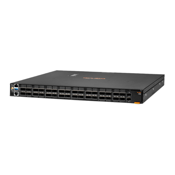
Chapter 1 Introducing the Switches Introducing the Switches Aruba 9300-32D multiport switches are store-and-forward devices offering low latency for high-speed networking with full network management capabilities. This chapter describes these switches with the following information: Front of the switches: Network ports Management ports Chassis and Port LEDs LED behavior... -
Page 9: Network Ports
Label Description Clock output connector OOBM Management port USB Type-A auxiliary port QSFP56-DD ports SFP+ ports Switch product label. Pull the tab out to view the product label information. Reset button RJ-45 console port Micro USB console port Network Ports Switch Model name SFP+ ports... -
Page 10: Out-Of-Band Management (Oobm) Port
Aruba 9300-32D switches include an RJ-45 serial console port on the front of the switch. This port is used to connect a console to the switch by using an RJ-45 serial cable (not supplied). A DB9-to-RJ-45 console cable can be ordered from HPE: JL448A, Aruba X2C2 RJ45 to DB9 Console Cable. The 9300-32D switches also include a micro-USB port on the front of the switch. -
Page 11: Led Behavior
Figure 1 Chassis and Port LEDs for the Aruba 9300-32D Label Description Locator / UID LED Global Status LED PSU1 LED PSU2 LED Fan LED Port LEDs QSFP56-DD port LEDs SFP+ port LEDs LED Behavior Switch LEDs Function LED State Meaning Behavior Displays Startup... - Page 12 Switch LEDs Function LED State Meaning Behavior with Global Status LED. QSFP-DD port Displays Startup On Green OS-CX: Default indicator in split Link SVOS: Default mode, all lanes information correspond to the for the single LED port. Normal No valid link On Green Valid link indication on one or more lanes.
- Page 13 Switch LEDs Function LED State Meaning Behavior SVOS: Self test failure Unit Customer Normal User defined the locator led: OFF Identification/Locator selectable through CLI to help ID/Locate unit. On/Flashing Blue (30 User define the locator led: min) On/Flash Fault Not implemented No fault defined PSU 1 and PSU 2 Indicates...
-
Page 14: Switch Product Label
Switch LEDs Function LED State Meaning Behavior module. Fault Flash Amber PSU FW upgrade in progress. PSU fan faults, no AC to both PSU, PSU in protection mode or system did not send PSOK. Switch Product Label The switch product label is an Aruba Orange-colored tab on the bottom right side of the switch front panel. Pull the tab out to view the product label information. -
Page 15: Power Supplies
Label Description Power Supply 1 Fan Tray 1 Fan Tray 2 Fan Tray 3 Fan Tray 4 Fan Tray 5 Fan Tray 6 Power Supply 2 Figure 2 LEDs and components on the back of the switch Label Description Ground lug PSU status LED Inlet C14 Sockets Fan Tray status LED... - Page 16 System airflow direction is configured automatically at system initialization and cannot be reconfigured by the user. System airflow direction is determined by the power supply type installed in PS1 at initialization time (or PS2 if PS1 is absent or faulted). Any fan tray or power supply of conflicting airflow type will be disabled by the system.
-
Page 17: Power Supply Instructions
Aruba 9300 1500W 100-240VAC Front-to-Back AC Power Supply Aruba 9300 1500W 100-240VAC Back-to-Front AC Power Supply Power Supply Instructions For indoor use only. The switch, AC power cord and all connected cables are not designed for outdoor use. During installation, ensure that AC power is NOT connected to the power supply being installed. Introducing the Switches... -
Page 18: Power Supply Status Led
Shock hazard. To completely remove power from the switch, disconnect all power cords. For important safety, environmental, and regulatory information, see Safety and Compliance Information for Server, Storage, Power, Networking, and Rack Products, available at http://www.hpe.com/support/Safety-Compliance-EnterpriseProducts Brazil Statement Este equipamento deve ser conectado obrigatoriamente em tomada de rede de energia elétrica que possua aterramento (três pinos), conforme a Norma NBR ABNT 5410, visando a segurança dos usuários contra choques elétricos.) Power Supply Status LED... -
Page 19: Fan Trays
Never insert or remove a power supply while the power cord is connected. Verify that the cord has been disconnected from the power supply before installation or removal. Fan Trays The switch is equipped with six field-replaceable, hot-swappable fan trays. Each fan tray features individual fans that pull air through the chassis from front to back or back to front. -
Page 20: Fan Tray Status Led
Figure 1 Aruba 9300-32D fan trays The switch can tolerate the failure of a single fan tray while maintaining a safe operating temperature. The switch may continue to operate with one failed fan tray. If the switch reaches a critical temperature condition, the switch will shut down. - Page 21 QSFP-DD, QSFP28, SFP28, SFP+. For a secure environment, all ports are disabled by default. Dual power supplies: Adding a second power supply provides redundant system power. If one of the power supplies fails, the second power supply continues to provide the power necessary to keep the switch running. Easy management of the switch through several available interfaces: Command line interface: A full-featured, easy-to-use, VT-100 terminal interface for out-of-band switch management.
-
Page 22: Installing The Switch
Chapter 2 Installing the switch Installing the switch The following sections show how to install the switch. For mounting options, see Mount the Switch on page or contact your Aruba representative or Aruba authorized reseller. Included Parts The 9300-32D switch is shipped with the following components: Documentation kit JL482C, Aruba Universal 2-Post Rack Mount Kit USB Bluetooth adapter: Enables you to configure your switch from a mobile device. -
Page 23: Installation Procedures For 9300-32D Switches
If you have not already done so, order an Aruba rack mount kit for use with your switch. Rack mounting your Aruba 9300-32D switch is supported using these rack mount kits: JL483C, Aruba Universal 4-Post Rack Mount Kit (Ordered separately) JL448A, Aruba X2C2 RJ45- DB9 Console cable (Ordered separately) Installation Procedures for 9300-32D Switches Prepare the Installation Site on page 24... -
Page 24: Prepare The Installation Site
Do not ship any switch in a rack without checking for restrictions in the latest Aruba Installation and Getting Started Guide. Otherwise, you may void the switch warranty. Ensure the power source circuits are properly grounded, then connect the switch to the power source by using the power cord supplied with the switch. -
Page 25: Install Power Supplies
To avoid personal injury or product damage, review Installation Precautions and Guidelines on page before starting installation. Install Power Supplies Prerequisites Skip this step if two power supplies are already installed in the switch If two power supplies are not already installed in the switch, install power supplies in both slots before proceeding. -
Page 26: Power-On The Switch And Check Leds
Figure 1 Installing a fan tray Power-on the switch and check LEDs Prerequisites The switch does not contain a power on/off switch. It is turned on by connecting the AC power cord to the switch and an AC power source. Check LEDs for proper switch operation. -
Page 27: Two-Post Rack Mount Option
Figure 1 Aruba X474 4-post Rack Kit (JL483C) 4-Post rack mountable with 4-Post rack mount kit in front-to-back and back-to-front configurations. Figure 2 Installation Precautions and Guidelines on page 23 before mounting your switch. Two-post Rack Mount Option The switch is designed to be mounted in any EIA-standard 19-inch telco rack or communication equipment cabinet using the Aruba X472 2-post Rack Kit (JL482C;... - Page 28 For safe operation, please review the mounting precautions in Installation Precautions and Guidelines, before mounting a switch. The 12-24 screws supplied with the two-post rack mount kit are the correct threading for standard EIA/TIA open 19- inch racks. If installing the switch in an equipment cabinet such as a server cabinet, use the clips and screws that came with the cabinet in place of the 12-24 screws that are supplied with the two-post rack mount kit.
-
Page 29: Four-Post Rack Mount Option
Figure 2 Mounting the switch in a two-post rack (Center-of-Gravity position) Four-Post Rack Mount Option The Aruba 9300-32D switch can be mounted in four-post racks and cabinets by using the Aruba X474 4- post Rack Kit (JL483C). For safe operation, please read the mounting precautions in Installation Precautions and Guidelines on page 23, before mounting a switch. - Page 30 1. Use a screwdriver and attach the front-post and rear-post rack mount brackets to the switch with the included 6-mm M4 screws. Figure 1 Attaching four-post mounting brackets to the switch For safe, reliable installation, only use the screws provided in the accessory kit to attach the mounting brackets to the switch.
- Page 31 Figure 2 Attaching rack slides to the side of the switch 3. Secure the rear post brackets to the rack rear posts using two number 10-32 screws. Figure 3 Securing rear post brackets to the rear post 4. Secure the chassis to the rack. Installing the switch...
-
Page 32: Install Transceivers
Figure 4 Securing chassis to the rack 5. Lock the position of the rear post bracket ears using the included position-locking screws. Figure 5 Locking the position for the rear post bracket ears Install Transceivers Hold the transceiver by its sides and gently insert it into the switch until it clicks into place. When a transceiver is inserted, the switch will authenticate it. -
Page 33: Connect The Switch To A Power Source
The Aruba transceivers are Class 1 laser devices. Avoid direct eye exposure to the beam coming from the transmit port. The transceivers operate only at full duplex. Half duplex operation is not supported. Use of supported genuine Aruba transceivers is always recommended. Non-Aruba SFP28/QSFP+/QSFP28 transceivers are not supported. -
Page 34: Setup For Initial Configuration
the PSU uses High Line (220VAC). For production environment, the 9300-32D requires High Line (220VAC) to ensure proper operations. One power supply with high line power provides power to operate the switch. Installing a second power supply can provide power to the switch in case the initial power supply fails. If the power supplies are plugged into different AC power sources, redundant power can be supplied in case of loss of one of the AC power sources. -
Page 35: Connecting Cables To Transceivers
If the Link LED does not turn on when the network cable is connected to the port, see Diagnosing with the LEDs in the Troubleshooting chapter. To disconnect: Press the small tab on the plug and pull the plug out of the port. Connecting Cables to Transceivers If you have any transceivers installed in the switch, the type of network connections you will need to use depends on the type of transceivers installed. -
Page 36: Initial Configuration With An Out-Of-Band Serial Connection
Chapter 3 Initial Configuration with an Out-of- Band Serial Connection Initial Configuration with an Out-of-Band Serial Connection Terminal Configuration To connect a console to the switch, configure the PC terminal emulator as a DEC VT-100 (ANSI) terminal or use a VT-100 terminal, and configure either one to operate with these settings: A baud rate of 115200. -
Page 37: Rj-45 To Db-9 Pinouts
RJ-45 to DB-9 pinouts DB-9 Signals (Sig- RJ-45 Signals (Signal reference RJ-45 Pin DB9 Pin nal reference from from chassis) Reserved Reserved Reserved Reserved Reserved No connection Initial Configuration with an Out-of-Band Serial Connection... -
Page 38: Replacing Components
Chapter 4 Replacing Components Replacing Components This chapter describes how to remove and install the following components: Power supply Fan tray The power supplies and fan trays are hot swappable. You do not need to power off the switch before installing or replacing a power supply or fan tray. -
Page 39: Replacing A Fan Tray
1. Remove the AC power cable from the power supply’s connector. 2. Grasping the handle of the failed power supply, use the Release Lever to release the locking mechanism and slide the power supply out of the switch. Figure 1 Replacing a failed power supply Label Description Release Lever... - Page 40 The Aruba 9300-32D switch is equipped with six field-replaceable, hot-swappable fan trays. The switch can tolerate the failure of a single fan tray while maintaining a safe operating temperature. To maintain system redundancy, a failed fan tray should be replaced as soon as possible. The Fan LED, Global Status LED, and Fan tray LED will FLASH amber, indicating a fan tray has failed.
- Page 41 Replacing Components...
-
Page 42: Troubleshooting
Chapter 5 Troubleshooting Troubleshooting This chapter describes how to troubleshoot your switch. This document describes troubleshooting primarily from a hardware perspective. You can perform more in-depth troubleshooting on these devices using the software tools available with the switches, including the full-featured console interface, the built-in web browser interface, Aruba Central, or Aruba AirWave. -
Page 43: Diagnosing With The Leds
Diagnosing with the LEDs LED Patterns for General Switch Troubleshooting 1. Check in the table for the LED pattern you see on your switch. 2. Refer to the corresponding diagnostic tip on the next few pages. PSU1, Global Status Fan tray Diagnostic PSU1/PSU2 LEDs PSU2,... - Page 44 Problem Solution by plugging another device into the outlet. Or try plugging the switch into a different outlet or try a different power cord. If the PS1/PS2 LED is still not on, verify the AC power source works by plugging another device into the outlet, try plugging the switch into a different outlet, or try a different power cord.
-
Page 45: Hardware Diagnostic Tests
Problem Solution operating correctly. Verify you have used the correct cable type for the connection: For fiber-optic connections, verify the transmit port on the switch is connected to the receive port on the connected device, and the switch receive port is connected to the transmit port on the connected device. -
Page 46: Checking The Switch Leds
Unplug and plug in the power cord (power cycling). Wait a minimum of five seconds after unplugging, before plugging the power cord back in. Reboot the switch through the CLI with the boot system command. Power cycling the switch causes the switch to reset. The reset process also causes any network traffic counters and the System Up Time timer to reset to zero. - Page 47 A risk of explosion exists if a battery is replaced by an incorrect type. Dispose of used batteries according to the battery disposal regulations for your country or region. ll y a danger d'explosion s'il y a remplacement incorrect de la batterie. Remplacer uniquement avec une batterie du même type ou d'un type équivalent recommandé...
-
Page 48: Specifications
Chapter 6 Specifications Specifications Physical Item Dimensions (W x D x H) Weight 33.7 lb (15.29 kg) R9A29A 24" x 32.9" x 8.3" (60.96 x 83.57 x 21.08 cm) R9A30A 24" x 32.9" x 8.3" (60.96 x 83.57 x 21.08 cm) 33.7 lb (15.29 kg) R8Z96A 24"... -
Page 49: Power Consumption
Only Aruba-approved power cords may be used with Aruba devices. To access power cord information for your switch, see Included Parts. Lost or damaged power cords must be replaced only with Aruba- approved power cords. If your installation requires a different power cord than the one supplied with the switch and/or power supply, be sure that the cord is adequately sized for the current requirements of the switch. -
Page 50: Rohs
Specifications Operating relative humidity 5% to 95% @ 104°F (40°C) non-condensing Non-operating temperature -40°F to 158°F (-40°C to 70°C) up to 15000 ft Non-operating storage relative humidity 5% to 90% @ 149°F (65°C) non-condensing Max operating altitude 10000 ft (3km) Max Max non-operating altitude 15000 ft (4.5km) Max RoHS... -
Page 51: Connectivity Standards
When selecting a fiber SFP or QSFP device, make sure the device has the same (or better) operating temperature range as the switch. Use only an approved Laser Class 1 SFP transceiver. Japan Power Cord Warning Connectivity Standards See the latest Transceiver Guide for your Aruba 9300-32D series switch at the Aruba Support Portal. Specifications... -
Page 52: Cabling And Technology Information
Chapter 7 Cabling and Technology Information Cabling and Technology Information This chapter includes switch connector information and network cable information for cables that should be used with Aruba 9300 switches. Incorrectly wired cabling is a common cause of problems for LAN communications. Aruba recommends that you work with a qualified LAN cable installer for assistance with your cabling requirements. -
Page 53: Technology Distance Specifications
1000BASE-T cable requirements The Category 5 networking cables that work for 100BASE-TX connections should also work for 1000BASE-T, as long as all four-pairs are connected. But, for the most robust connections, you should use cabling that complies with the Category 5e specifications, as described in Addendum 5 to the TIA- 568-A standard (ANSI/TIA/EIA-568-A- 5). - Page 54 Supported cable Multimode fibermodal Technology Supported distances type bandwidth 400 MHz*km 2 - 500 meters 500 MHz*km 2 - 550 meters 1000BASE-LX Single mode fiber 2 - 10,000 meters 1000BASE-LH Single mode fiber 2 - 70,000 meters 10GBASE-T Twisted-pair copper Cat 6A unshielded - up to 100 meters Cat 6A shielded - up to 100...
- Page 55 Supported cable Multimode fibermodal Technology Supported distances type bandwidth 40GBASE-ER4 single mode fiber 2 - 40,000 meters 40GBASE-BiDi multimode fiber 1500 MHz*km 2 - 100 meters 3500 MHz*km 2 - 150 meters 100GBASE-CR4 twinaxial copper (various lengths offered) 100GBASE-SR4 multimode fiber 1500 MHz*km 2 - 100 meters 3500 MHz*km...
-
Page 56: Support And Other Resources
Chapter 8 Support and other resources Support and other resources Accessing Aruba Support Aruba Support https://www.arubanetworks.com/support- Services services/ Aruba Support Portal https://asp.arubanetworks.com/ North America 1-800-943-4526 (US & Canada Toll-Free telephone Number) +1-408-754-1200 (Primary - Toll Number) +1-650-385-6582 (Backup - Toll Number - Use only when all other numbers are not working) International... -
Page 57: Aruba Support Portal
Access to some updates might require product entitlement when accessed through the Hewlett Packard Enterprise Support Center. You must have an HP Passport set up with relevant entitlements. Some software products provide a mechanism for accessing software updates through the product interface.
Need help?
Do you have a question about the aruba 9300-32D Series and is the answer not in the manual?
Questions and answers