Advertisement
Quick Links
© Copyright 2005 Hewlett-Packard
Development Company, L.P. The
information contained herein is subject to
change without notice.
Part Number: 5991-2188
Edition 1, September 2005
*5990-
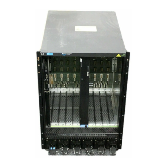
ProCurve 9408sl Routing Switch Fan Assembly
Replacement Instructions
This booklet describes the procedures to replace the fan assembly in your ProCurve 9408sl Routing
Switch. The fan assembly consists of two separate items: a fan control module, and the fan itself.
Both items must be replaced in the event of a fan failure. Because the ProCurve 9408sl has redundant
fan assemblies, you can replace a fan and fan control module while the chassis is powered on and
running. The fans and fan control modules are located on the rear panel of the ProCurve 9408sl
chassis.
Fan Assembly Installation Precautions
WARNINGS
■
WARNING: To reduce risk of electric shock, the ESD wrist strap must have a series 1 meg
ohm resistor.
■
WARNING: When removing the fan module, the fan may still be spinning. Be careful to not
accidentally insert your fingers into the fan while removing it from the chassis.
Cautions
■
Attach a properly grounded ESD wrist strap to your wrist when handling the fan and fan
control module. Do not touch the components or edge connectors on any printed circuit
boards, or the pins on any connectors. Otherwise, damage due to static discharge could
occur.
■
To avoid overheating the ProCurve 9408sl chassis, remove only one fan or fan control module
at a time. A minimum of one fan must remain operational at all times. Do not remove both
fan assemblies from the chassis at one time.
To replace a fan assembly, you need the following:
■
A new fan assembly, which you can order from HP after the warranty period. A new fan assembly
(part # J8680-80003) can be ordered from the HP Parts Store (Online Shopping) web page (URL
www.hp.com/buy/parts).
■
A small flathead screwdriver
■
A small Phillips screwdriver
■
An ESD wrist strap. If your ESD wrist strap has a "banana plug", it can be plugged into the ESD
connector on the ProCurve 9408sl chassis, located in the upper right corner of the chassis rear.
Replacing the Fan Assembly Procedure
Remove the fan control module:
1.
Put on the ESD strap and ground yourself by inserting the plug into the ESD connector located
in the upper right corner of the chassis rear.
2.
Using the Phillips screwdriver, loosen the two screws that secure the fan control module
(marked "FCM A" or "FCM B") to the chassis rear.
Advertisement

Related Manuals for HP ProCurve 9408sl


Summary of Contents for HP ProCurve 9408sl
- Page 1 Switch. The fan assembly consists of two separate items: a fan control module, and the fan itself. Both items must be replaced in the event of a fan failure. Because the ProCurve 9408sl has redundant fan assemblies, you can replace a fan and fan control module while the chassis is powered on and running.
- Page 2 Grasp fan control module here to pull it in seats the module connector with the chassis connector. out of chassis Secure the fan control module to the chassis by tightening the two screws. The ProCurve 9408sl initializes the replaced fan control module automatically. Verify successful operation: Observe the LED on the fan control module faceplate to verify that it is operating normally.
Need help?
Do you have a question about the ProCurve 9408sl and is the answer not in the manual?
Questions and answers