Table of Contents
Advertisement
Quick Links
Advertisement
Table of Contents

Subscribe to Our Youtube Channel
Related Manuals for HIKVISION DS-K3G501S Series


Summary of Contents for HIKVISION DS-K3G501S Series
- Page 1 DS-K3G501SX Series Tripod Turnstile Quick Start Guide...
- Page 2 WITHOUT LIMITATION, MERCHANTABILITY, SATISFACTORY QUALITY, OR FITNESS FOR A PARTICULAR PURPOSE. THE USE OF THE PRODUCT BY YOU IS AT YOUR OWN RISK. IN NO EVENT WILL HIKVISION BE LIABLE TO YOU FOR ANY SPECIAL, CONSEQUENTIAL, INCIDENTAL, OR INDIRECT DAMAGES,...
- Page 3 During the use of device, personal data will be collected, stored and processed. To protect data, the development of Hikvision devices incorporates privacy by design principles. For example, for device with facial recognition features, biometrics data is stored in your device with encryption method;...
- Page 4 DS-K3G501SX Series Tripod Turnstile Quick Start Guide Regulatory Information FCC Information Please take attention that changes or modification not expressly approved by the party responsible for compliance could void the user’s authority to operate the equipment. FCC compliance: This equipment has been tested and found to comply with the limits for a Class B digital device, pursuant to part 15 of the FCC Rules.
- Page 5 DS-K3G501SX Series Tripod Turnstile Quick Start Guide under the EMC Directive 2014/30/EU, RE Directive 2014/53/EU,the RoHS Directive 2011/65/EU 2012/19/EU (WEEE directive): Products marked with this symbol cannot be disposed of as unsorted municipal waste in the European Union. For proper recycling, return this product to your local supplier upon the purchase of equivalent new equipment, or dispose of it at designated collection points.
- Page 6 DS-K3G501SX Series Tripod Turnstile Quick Start Guide Safety Instruction These instructions are intended to ensure that user can use the product correctly to avoid danger or property loss. The precaution measure is divided into Dangers and Cautions: Dangers: Neglecting any of the warnings may cause serious injury or death. Cautions: Neglecting any of the cautions may cause injury or equipment damage.
- Page 7 DS-K3G501SX Series Tripod Turnstile Quick Start Guide Do not ingest battery, Chemical Burn Hazard. ● This product contains a coin/button cell battery. If the coin/button cell battery is swallowed, it can cause severe internal burns in just 2 hours and can lead to death. Keep new and used batteries away from children.
- Page 8 DS-K3G501SX Series Tripod Turnstile Quick Start Guide Do not place the device in extremely hot (refer to the specification of the device for the detailed ● operating temperature), cold, dusty or damp locations, and do not expose it to high electromagnetic radiation.
- Page 9 DS-K3G501SX Series Tripod Turnstile Quick Start Guide Available Models Product Name Model Tripod Turnstile DS-K3G501SX Scan the QR code to get User Manual of Tripod Turnstile. Note that mobile data charges may apply if Wi-Fi is unavailable. Figure 1-1 QR Code viii...
-
Page 10: Table Of Contents
DS-K3G501SX Series Tripod Turnstile Quick Start Guide Contents Chapter 1 Overview ........................1 1.1 Introduction ........................... 1 1.2 Main Features ........................1 Chapter 2 System Wiring ......................3 Chapter 3 Installation ......................... 5 3.1 Disassemble Pedestals ......................5 3.2 Install Pedestals ........................5 Chapter 4 General Wiring ...................... - Page 11 DS-K3G501SX Series Tripod Turnstile Quick Start Guide Appendix A. Tips for Scanning Fingerprint ................29 Appendix B. DIP Switch ......................31 B.1 DIP Switch Description ......................31 B.2 DIP Switch Corresponded Functions ..................31 Appendix C. Event and Alarm Type ................... 33 Appendix D.
-
Page 12: Chapter 1 Overview
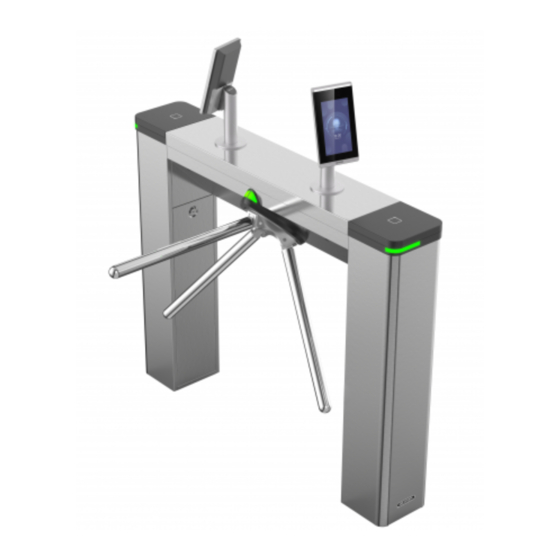
DS-K3G501SX Series Tripod Turnstile Quick Start Guide Chapter 1 Overview 1.1 Introduction The tripod turnstile is designed to detect unauthorized entrance or exit. By adopting the turnstile integratedly with the access control system, person should authenticate to pass through the lane via swiping IC or ID card, scanning QR code, etc. - Page 13 DS-K3G501SX Series Tripod Turnstile Quick Start Guide Self-detection, Self-diagnostics, and automatic alarm ● Remote control and management ● Online/offline operation ● LED indicates the entrance/exit and passing status ● Barrier is in free status when powered down. People can pass through the lane along single/both ●...
-
Page 14: Chapter 2 System Wiring
DS-K3G501SX Series Tripod Turnstile Quick Start Guide Chapter 2 System Wiring The preparation before installation and general wiring. Steps 1. Draw a central line on the installation surface of the left or right pedestal. 2. Draw other parallel lines for installing the other pedestals. Note The distance between the nearest two line is 782 mm. - Page 15 DS-K3G501SX Series Tripod Turnstile Quick Start Guide Figure 2-2 System Wiring Diagram Note The suggested inner diameter of the low voltage conduit is larger than 30 mm. ● If the face recognition module are required to be connected on the left lane, you should ●...
-
Page 16: Chapter 3 Installation
DS-K3G501SX Series Tripod Turnstile Quick Start Guide Chapter 3 Installation 3.1 Disassemble Pedestals Before installation, you should use the key to open the pedestals. View the pictures below to find the lock holes. Figure 3-1 Lock Holes 3.2 Install Pedestals Before You Start Prepare for the installation tools, check the device and the accessories, and clear the installation base. - Page 17 DS-K3G501SX Series Tripod Turnstile Quick Start Guide Face recognition terminal installed: If the installation area is too close to the wall, make sure the distance between the pedestal and the wall should be more than 130 mm, or the surface may be scratched.
- Page 18 DS-K3G501SX Series Tripod Turnstile Quick Start Guide Figure 3-2 Dimension 1. Prepare for the installation tools, check the components, and prepare for the installation base. 2. Drill holes on the ground according to the installation holes on the pedestals and insert the expansion sleeves.
- Page 19 DS-K3G501SX Series Tripod Turnstile Quick Start Guide Figure 3-3 Installation Footprint...
-
Page 20: Chapter 4 General Wiring
DS-K3G501SX Series Tripod Turnstile Quick Start Guide Chapter 4 General Wiring 4.1 Components Introduction By default, basic components of the turnstile are connected well. The turnstile supports wiring the AC electric supply for the whole system's power supply. Note The voltage fluctuation of the electric supply is between 100 VAC and 220 VAC, 50 to 60 Hz. The picture displayed below describes each component's position on the turnstile. -
Page 21: Terminal Description
DS-K3G501SX Series Tripod Turnstile Quick Start Guide Warning Terminal PE should connect to a ground wire to avoid hazard when people touching the device. Note The cable bare part should be no more than 8 mm. If possible, wear an insulation cap at the end ●... - Page 22 DS-K3G501SX Series Tripod Turnstile Quick Start Guide Figure 4-2 Access Control Board Diagram Table 4-1 Table of Access Control Board Terminal Description Access Control Board Terminal Description 24 V Power Input +24 V Power Input Grounding Wiegand Card Indicator of Card Reader Control Output (Invalid Card Reader 1 Output) Indicator of Card Reader Control Output (Valid Card...
- Page 23 DS-K3G501SX Series Tripod Turnstile Quick Start Guide Access Control Board Terminal Description Wiegand Card Indicator of Card Reader Control Output (Invalid Card Reader 2 Output) Indicator of Card Reader Control Output (Valid Card Output) Card Reader Buzzer Control Output Wiegand Head Read Data Input Data1 Wiegand Head Read Data Input Data0 Grounding RS-485 Interface (In...
- Page 24 DS-K3G501SX Series Tripod Turnstile Quick Start Guide Access Control Board Terminal Description Door 1 Signal Input Door Lock Door 1 Relay Output (Dry Contact) Door 2 Relay Output (Dry Contact) Alarm Output1/ NO/NC1 Alarm Output Relay 1 (Dry Contact) Alarm Output 2 COM1 NO/NC2 Alarm Output Relay 2 (Dry Contact)
- Page 25 DS-K3G501SX Series Tripod Turnstile Quick Start Guide Terminal Group Terminal Name Color Description QR Code Scanner 5 V Power Terminal Terminal Group 232+ Blue Connect to QR Code Scanner RS-232+ 232- Green Connect to QR Code Scanner RS-232- Black Grounding Tamper Terminal TAMPER Brown...
-
Page 26: Access Control Board Serial Port Id Description
DS-K3G501SX Series Tripod Turnstile Quick Start Guide 4.3.2 Access Control Board Serial Port ID Description You can use the jumper cap on the access control board to switch the interface communication mode. For details about switching between RS-232 and RS-485 communication type, see Switching RS-485/RS-232 Mode. - Page 27 DS-K3G501SX Series Tripod Turnstile Quick Start Guide Serial Port 3 Jumper Cap Use the jumper cap to switch the serial port communication mode. You can switch between the RS-232 communication mode and the RS-485 communication mode. By default, it is in RS-232 communication mode.
-
Page 28: Rs-485 Wiring
DS-K3G501SX Series Tripod Turnstile Quick Start Guide 4.3.3 RS-485 Wiring Note There are four RS-485 interfaces, which are for connecting ID card reader, IC card reader, QR ● code scanner, fingerprint and card reader, card recycler, text screen, fingerprint reader, and face recognition terminal. -
Page 29: Rs-232 Wiring
DS-K3G501SX Series Tripod Turnstile Quick Start Guide 4.3.4 RS-232 Wiring Note The RS-232 interfaces can connect QR code scanner, and card recycler. ● For details about text screen, see Configuring Screen Parameters in User Manual of iVMS-4200 ● AC Client Software. Take the wiring of text screen as an example. -
Page 30: Wiegand Wiring
DS-K3G501SX Series Tripod Turnstile Quick Start Guide 4.3.5 Wiegand Wiring Note Connect the OK/ERR/BZ if the access controller should control the LED and buzzer of the Wiegand card reader. 4.3.6 Barrier Control Wiring By default, the barrier has connected with the access control board. If possible, the device can connect with a third party control board to control the third party barriers. - Page 31 DS-K3G501SX Series Tripod Turnstile Quick Start Guide Note The output signal is relay. The terminals cannot connect with the devices carrying voltage. Entering Wiring...
-
Page 32: Alarm Output Wiring
DS-K3G501SX Series Tripod Turnstile Quick Start Guide Exiting Wiring 4.3.7 Alarm Output Wiring Note For details about changing the relay output status via the jumper cap, see Alarm Relay Output Mode (NO/NC) . -
Page 33: Chapter 5 Device Settings
DS-K3G501SX Series Tripod Turnstile Quick Start Guide Chapter 5 Device Settings You can also set the turnstile to passing mode and memory mode, pair the keyfob, initialize the hardware, switching between RS-485 communication mode and RS-232 communication mode, and view relay output NO/NC diagram by setting the DIP switch on the access control board. Normal Mode: The device will work properly. -
Page 34: Initialize Device
DS-K3G501SX Series Tripod Turnstile Quick Start Guide 3. Power on the turnstile and it will enter the keyfob pairing mode. 4. Hold the Close button for more than 10 seconds. Or pair turnstile and keyfob in the client software, see Manage Keyfob User of the user manual for more details. The keyfob's indicator of the will flash twice if the pairing is completed. -
Page 35: Switch To Rs-485/Rs-232 Mode
DS-K3G501SX Series Tripod Turnstile Quick Start Guide Figure 5-1 Initialization Jumper Cap 2. Disconnect the power and reboot the device. The device buzzer buzzes a long beep. 3. When the beep stopped, plug the jumper cap back. 4. Disconnect the power and power on the device again. Caution The initialization of the device will restore all the parameters to the default setting and all the device events are deleted. -
Page 36: Alarm Relay Output Mode (No/Nc)
DS-K3G501SX Series Tripod Turnstile Quick Start Guide Figure 5-2 Jumper Cap Status of RS-485 Interface If the Jumper cap's position is like the picture displayed below. (The black part is the jumper cap.) The serial port is in RS-232 communication mode. Figure 5-3 Jumper Cap Status of RS-232 Interface 5.4 Alarm Relay Output Mode (NO/NC) Alarm Relay Output Mode (NO):... -
Page 37: Chapter 6 Activation
Get the SADP software from the supplied disk or the official website http:// ● www.hikvision.com/en/ , and install the SADP according to the prompts. The device and the PC that runs the SADP tool should be within the same subnet. -
Page 38: Activate Device Via Ivms-4200 Client Software
DS-K3G501SX Series Tripod Turnstile Quick Start Guide Status of the device becomes Active after successful activation. 5. Modify IP address of the device. 1) Select the device. 2) Change the device IP address to the same subnet as your computer by either modifying the IP address manually or checking Enable DHCP. - Page 39 DS-K3G501SX Series Tripod Turnstile Quick Start Guide Caution The password strength of the device can be automatically checked. We highly recommend you change the password of your own choosing (using a minimum of 8 characters, including at least three kinds of following categories: upper case letters, lower case letters, numbers, and special characters) in order to increase the security of your product.
-
Page 40: Appendix A. Tips For Scanning Fingerprint
DS-K3G501SX Series Tripod Turnstile Quick Start Guide Appendix A. Tips for Scanning Fingerprint Recommended Finger Forefinger, middle finger or the third finger. Correct Scanning The figure displayed below is the correct way to scan your finger: You should press your finger on the scanner horizontally. The center of your scanned finger should align with the scanner center. - Page 41 DS-K3G501SX Series Tripod Turnstile Quick Start Guide Environment The scanner should avoid direct sun light, high temperature, humid conditions and rain. When it is dry, the scanner may not recognize your fingerprint successfully. You can blow your finger and scan again. Others If your fingerprint is shallow, or it is hard to scan your fingerprint, we recommend you to use other authentication methods.
-
Page 42: Appendix B. Dip Switch
DS-K3G501SX Series Tripod Turnstile Quick Start Guide Appendix B. DIP Switch B.1 DIP Switch Description The DIP switch is on the access control board. No.1 to No 8 is from the low bit to the high bit. When the switch is towards ON, it means the switch is enabled, otherwise, the switch is off. If you set the DIP switch like the figure displayed below, its binary value is 00001100, and its decimal value is 12. - Page 43 DS-K3G501SX Series Tripod Turnstile Quick Start Guide Device Mode Function Decimal Value Binary Value 5 to 8 Passing Mode Controlled Bi- direction Controlled Entrance and Prohibit Exit Controlled Entrance and Free Exit Free Bi- d irection Free Entrance and Controlled Exit Free Entrance and Prohibit Exit Prohibited Bi-...
-
Page 44: Appendix C. Event And Alarm Type
DS-K3G501SX Series Tripod Turnstile Quick Start Guide Appendix C. Event and Alarm Type Event Alarm Type Passing Timeout None... -
Page 45: Appendix D. Table Of Audio Index Related Content
DS-K3G501SX Series Tripod Turnstile Quick Start Guide Appendix D. Table of Audio Index Related Content Index Content Authenticated. Card No. does not exist. Card No. and fingerprint mismatch. Passing timeout. No permissions. Authentication time out. Authentication failed. Expired card. -
Page 46: Appendix E. Communication Matrix And Device Command
Device Command Scan the following QR code to get the device common serial port commands. Note that the command list contains all commonly used serial ports commands for all Hikvision access control and video intercom devices. Figure E-2 Device Command... - Page 47 UD25709B...
Need help?
Do you have a question about the DS-K3G501S Series and is the answer not in the manual?
Questions and answers