Table of Contents
Advertisement
Quick Links
Advertisement
Table of Contents

Related Manuals for HIKVISION DS-K3B601-L Series


Summary of Contents for HIKVISION DS-K3B601-L Series
- Page 1 Swing Barrier Quick Start Guide...
- Page 2 This Manual is subject to domestic and international copyright protection. Hangzhou Hikvision Digital Technology Co., Ltd. (“Hikvision”) reserves all rights to this manual. This manual cannot be reproduced, changed, translated, or distributed, partially or wholly, by any means, without the prior written permission of Hikvision.
- Page 3 Swing Barrier Quick Start Guide Regulatory Information FCC Information Please take attention that changes or modification not expressly approved by the party responsible for compliance could void the user’s authority to operate the equipment. FCC compliance: This equipment has been tested and found to comply with the limits for a Class B digital device, pursuant to part 15 of the FCC Rules.
- Page 4 Swing Barrier Quick Start Guide 2006/66/EC (battery directive): This product contains a battery that cannot be disposed of as unsorted municipal waste in the European Union. See the product documentation for specific battery information. The battery is marked with this symbol, which may include lettering to indicate cadmium (Cd), lead (Pb), or mercury (Hg).
- Page 5 Swing Barrier Quick Start Guide Warnings Follow Cautions Follow these these safeguards to precautions to prevent prevent serious potential injury injury or death. material damage. Warnings All the electronic operation should be strictly compliance with the electrical safety regulations, fire prevention regulations and other related regulations in your local region.
- Page 6 Swing Barrier Quick Start Guide Please use a soft and dry cloth when clean inside and outside surfaces of the device cover, do not use alkaline detergents. Please keep all wrappers after unpack them for future use. In case of any failure occurred, you need to return the device to the factory with the original wrapper.
-
Page 7: Table Of Contents
Swing Barrier Quick Start Guide Table of Contents Chapter 1 Overview ......................... 1 Introduction ......................... 1 Main Features ........................1 Chapter 2 Installation ......................2 Disassembling Pedestals....................... 2 Installing Pedestals ....................... 2 Chapter 3 Wiring ........................4 Components Introduction ....................4 Wiring Electric Supply ...................... - Page 8 Swing Barrier Quick Start Guide DIP Switch Corresponded Functions ....................26 Appendix B Table of Audio Index Related Content ..............28 Appendix C Error Code Description ..................29...
-
Page 9: Chapter 1 Overview
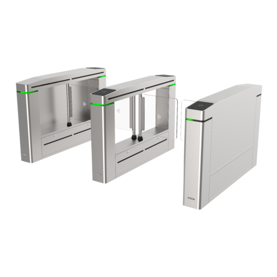
Swing Barrier· Quick Start Guide Chapter 1 Overview 1.1 Introduction The swing barrier with two barriers and 12 IR lights is designed to detect unauthorized entrance or exit. By adopting the swing barrier integratedly with the access control system, person should authenticate to pass through the lane via swiping IC or ID card, scanning QR code, etc. -
Page 10: Chapter 2 Installation
Swing Barrier· Quick Start Guide Chapter 2 Installation 2.1 Disassembling Pedestals Purpose: Before installation, you should use the key to open the pedestals. View the pictures below to find the locks and installation holes. 2.2 Installing Pedestals Before you start: Prepare for the installation tools, check the device and the accessories, and clear the installation base. - Page 11 Swing Barrier· Quick Start Guide Note: For detailed information about burying and wiring interconnecting cables, see 3.3 Wiring Interconnecting Cable. 5. According to the entrance and exit marks on the pedestals, move the pedestals to the corresponded positions. Note: Make sure the installation holes on the pedestals and the base are aligned with each other.
-
Page 12: Chapter 3 Wiring
Swing Barrier· Quick Start Guide Chapter 3 Wiring 3.1 Components Introduction Purpose: By default, basic components of the swing barrier are connected well. You should wire the pedestals together for communication and wire the swing barrier to the AC electric supply. Note: The voltage fluctuation of the electric supply is between 100 VAC and 220 VAC, 50 to 60 Hz. -
Page 13: Wiring Interconnecting Cable
Swing Barrier· Quick Start Guide 3.3 Wiring Interconnecting Cable Purpose: You should use interconnecting cables to connect the master lane board and the slave lane board for components communication. The picture displayed below describes the interconnecting cable hole’s position on the pedestals. - Page 14 Swing Barrier· Quick Start Guide The picture displayed below describes the interconnecting cable’s wiring diagram. Notes: The supplied interconnecting cable length is 3.75 m. If you need a longer one, ask our technique supports or sales and purchase 5.5 m interconnecting cables. ...
-
Page 15: Terminal Description
Swing Barrier· Quick Start Guide 3.4 Terminal Description Purpose: The lane controller contains master lane controller and slave lane controller, which controls the IR beams, motor, and other components work. 3.4.1 Master Control Board Terminal Description Purpose: The master lane control board contains lane communication interfaces, interconnecting interface, motor encoder interface, remaining open and fire alarm interface, barrier opening directions interface, people counting interface, remote control receiving antenna, motor drive interface, brake interface, power interface, battery interface, DIP switch, and seven-segment display. -
Page 16: Main Control Board Terminal Description
Swing Barrier· Quick Start Guide 3.4.3 Main Control Board Terminal Description... - Page 17 Swing Barrier· Quick Start Guide Table 3-1 Main Control Board Terminal Description Main Controlling Board Terminal Description Power +12V Grounding Output1 Power Output Indicator of Card Reader Control Output (Invalid Card Output) Indicator of Card Reader Control Output (Valid Wiegand Card Output) Card Card Reader Buzzer Control Output...
- Page 18 Swing Barrier· Quick Start Guide Main Controlling Board Terminal Description Grounding Event Alarm Input 1 Door 2 Signal Input Exit Button Grounding Door 1 Signal Input Door 1 Relay Output(Dry Contact) Door Lock (Relay) Door 2 Relay Output(Dry Contact) NO/NC1 Alarm Output Relay 1(Dry Contact) COM1 NO/NC2...
-
Page 19: Main Control Board Serial Port Id Description
Swing Barrier· Quick Start Guide 3.4.4 Main Control Board Serial Port ID Description Purpose: You can use the jumper cap on the main control board to switch the interface communication mode. For details about switching between RS-232 and RS-485 communication type, see 4.4 Switching RS-485/RS-232 Mode. -
Page 20: Rs-485 Wiring
Use the jumper cap to switch the serial port communication mode with the lane controller. By default, the interface is wired and it is in RS-485 communication mode. If wiring other controllers (compatible with Hikvision communication protocol), use the jumper cap to switch between RS-485 and RS-232 communication mode. -
Page 21: Rs-232 Wiring
Swing Barrier· Quick Start Guide Notes: There are five RS-485 interfaces, which are for connecting ID card reader, IC card reader, QR code scanner, fingerprint and card reader, card recycler, text screen, fingerprint reader, and face recognition terminal. Take the wiring of RS-485 card reader as an example. ... -
Page 22: Wiegand Wiring
Swing Barrier· Quick Start Guide 3.4.7 Wiegand Wiring Note: You must connect the OK/ERR/BZ if using access controller to control the LED and buzzer of the Wiegand card reader. 3.4.8 Barrier Control Wiring Purpose: By default, the barrier has connected with the main control board. The lane control board can control the barrier status. - Page 23 Swing Barrier· Quick Start Guide Entering Wiring Exiting Wiring...
-
Page 24: Alarm Output Wiring
Swing Barrier· Quick Start Guide 3.4.9 Alarm Output Wiring Note: For details about changing the relay output status via the jumper cap, see 4.5.2 Alarm Relay Output Mode (NO/NC). 3.5 Wiring Lithium Battery (Optional) Purpose: The lithium battery supplies power for master lane control board and slave lane control board when the device is powered off. - Page 25 Swing Barrier· Quick Start Guide...
-
Page 26: Chapter 4 Device Settings
Swing Barrier· Quick Start Guide Chapter 4 Device Settings Purpose: After installation and wiring completed, you should set the barriers closed position (study mode) before entering the working mode. You can also set the passing mode and memory mode, pair the remote control, initialize the hardware, switching between RS-485 communication mode and RS-232 communication mode, and view relay output NO/NC diagram by setting the DIP switch. -
Page 27: Pairing Remote Control (Optional)
Swing Barrier· Quick Start Guide 6. Power on the device again. The barrier will open automatically and turns back to the closed position. At this circumstance, the device enters the normal mode. Note: For details about the DIP switch value and meaning, see Appendix A DIP Switch Description. -
Page 28: Switching Relay Output Mode (No/Nc)
Swing Barrier· Quick Start Guide is like the picture displayed below. (The black part is the jumper cap.) The serial port is in RS-485 communication mode. If the Jumper cap’s position is like the picture displayed below. (The black part is the jumper cap.) The serial port is in RS-232 communication mode. -
Page 29: Alarm Relay Output Mode (No/Nc)
Swing Barrier· Quick Start Guide 4.5.2 Alarm Relay Output Mode (NO/NC) Alarm Relay Output Mode (NO): Alarm Relay Output Mode (NC):... -
Page 30: Chapter 5 Device Activation
Swing Barrier· Quick Start Guide Chapter 5 Device Activation Purpose: You are required to activate the terminal first before using it. Activation via SADP, and activation via client software are supported. The default values of the control terminal are as follows. ... -
Page 31: Activating Via Client Software
Swing Barrier· Quick Start Guide STRONG PASSWORD RECOMMENDED– We highly recommend you create a strong password of your own choosing (using a minimum of 8 characters, including upper case letters, lower case letters, numbers, and special characters) in order to increase the security of your product. - Page 32 Swing Barrier· Quick Start Guide 2. Click Device Management to enter the Device Management interface. 3. Check the device status from the device list, and select an inactive device. 4. Check the device status from the device list, and select an inactive device. 5.
- Page 33 Swing Barrier· Quick Start Guide 7. Click OK button to start activation. 8. Click the Modify Netinfor button to pop up the Network Parameter Modification interface. 9. Change the device IP address to the same network segment with your computer by either modifying the IP address manually.
-
Page 34: Appendix Adip Switch Description
Swing Barrier· Quick Start Guide Appendix A DIP Switch Description DIP Switch Introduction There are two groups of DIP switches on the master lane control board. Take the 8-bit DIP switch as an example; No.1 to No 8 is from the low bit to the high bit. When the switch is towards ON, it means the switch is enabled, otherwise, the switch is off. - Page 35 Swing Barrier· Quick Start Guide The 4-bit DIP switch corresponded functions on the master lane control board are as follows: Function Decimal Value Binary Value Normal Mode Remote Control Paring Mode Reserved...
- Page 36 Swing Barrier· Quick Start Guide Appendix B Table of Audio Index Related Content Index Content Authenticated. Card No. does not exist. Card No. and fingerprint mismatch. Climbing over the barrier. Reverse passing. Passing timeout. Intrusion. Force accessing. Tailgating. No permissions. Authentication time out.
- Page 37 Swing Barrier· Quick Start Guide Appendix C Error Code Description The swing barrier will display the error code on the seven-segment display if error occurred. Refer to the table below to find the description of each number. Error Reason Error Reason Normal Working IR Board 2 Offline The First IR Beam on IR Board...
- Page 38 Swing Barrier· Quick Start Guide UD08976B-B...
Need help?
Do you have a question about the DS-K3B601-L Series and is the answer not in the manual?
Questions and answers