Advertisement
Quick Links
Advertisement

Related Manuals for ITC PRECISION Series


Summary of Contents for ITC PRECISION Series
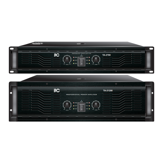
- Page 1 PROFESSIONAL POWER AMPLIFIERS OWNER'S MANUAL PROFESSIONAL POWER AMPLIFIER TA-2700 TA-21200 PROFESSIONAL POWER AMPLIFIER TA-2500/TA-2700/TA-2900/TA-21200 PROFESSIONAL POWER AMPLIFIER...
- Page 2 NOTES ● Please avoid using this equipment in the following places: Exposed to the splashing oil spray, steam, for example, places near the cooker, humidifier, etc. Unstable surface, such as rocky desktop or oblique plane. Exposed to overheating environment, such as car with window closed or places with direct sunlight. Exposed to high moist environment or places with lots of dust.
-
Page 3: Table Of Contents
OPERATION ● Please use special speaker cable when connect the speaker to amplifier output. It may cause fire if use other cables. ● Please power off all other instruments, audio device and speakers. And use the correct cables to connect accordingly. ●... -
Page 4: Description
DESCRIPTION Thank you very much for choosing an ITC PRECISION SERIES amplifier. We are sure it will give you many years of satisfying performance. ITC power amplifiers of the PRECISION SERIES meet the stringent requirements of tough touring applications. They are protected against over-temperature, overload, shorted outputs, radio freq- uency interference and DC faults. -
Page 5: Function And Features
FUNCTION AND FEATURES Function and Features: 1. Industrial modeling steel professional panel, solid and durable, washable panel with dust screen. 2. Soft start to prevent high current power absorbing and interfere with other electrical equipment. 3. Intelligent forced cooling design, with low fan noise, high heat dissipation and other features. 4. -
Page 6: Front Panel Function
FRONT PANEL FUNCTION Front panel(2U): Level Control Potentiometer controls amplifier’s input level, clockwise rotation to increase the volume, whereas the volume decreases. Power Switch After the switch is turned on, POWER lamp is lit and you can hear the "Tap" sound of the relay pull -in in the machine. - Page 7 FRONT PANEL FUNCTION Front panel(3U): Level Control Potentiometer controls amplifier’s input level, clockwise rotation to increase the volume, whereas the volume decreases. Power Switch After the switch is turned on, POWER lamp is lit and you can hear the "Tap" sound of the relay pull -in in the machine.
-
Page 8: Rear Panel Function
REAR PANEL FUNCTION Rear panel(2U): Channel A/B balanced and unbalanced input (Note: When using BRIDGE or PARALLEL mode, only the jack of channel A is effective). Channel A/B balanced LINK output. Amplifier channel A/B SPEAKER jacks Neutrik NL4FCSPEAKON is used as an output connection jack. AC power input Before connected to main grid, please check if the voltage is consistent with the marked. - Page 9 REAR PANEL FUNCTION Rear panel(3U): 1112 Channel A/B balanced and unbalanced input (Note: When using BRIDGE or PARALLEL mode, only the jack of channel A is effective). Channel A/B balanced LINK output. Amplifier channel A/B SPEAKER jacks Neutrik NL4FCSPEAKON is used as an output connection jack. AC power input Before connected to main grid, please check if the voltage is consistent with the marked.
-
Page 10: Connection Methods
CONNECTION METHODS Connection methods: XLR connector is the connector for balancing transmission signal. The definition of each input pin is: PIN 1: Ground PIN 2: Signal Hot End PIN 3: Signal Cold End OUTPUT INPUT For unbalanced input method, PIN 1 and PIN 3 are short-circuiting. Input sensitivity is 1V. Amplifier output connector: SPEAKON speaker connected dedicated connector, bridging CHA SPEAKON available Bridged output, use binding post... -
Page 11: The Connection Of The Speaker
THE CONNECTION OF THE SPEAKER The impedance of the speaker: Connect the speaker as shown below: ① ② Under the STEREO and PARALLEL mode to Under the BRIDGE mode to connect the connect the configuration, when use the binding configuration, when use the binding post post socket: socket: SPK-... -
Page 12: Rear Panel Wiring Diagram
REAR PANEL WIRING DIAGRAM Rear panel wiring diagram(2U): SPEAKER SPEAKER AMPLIFIER 2--OUTPUTS--1 LINE 10 LINE 9 LINE 8 LINE 7 MIC INPUTS MIC/LINE INPUTS PRIORITY CHIME 220V/50Hz LED PWR MAX 9.9W MIC INPUT P.T.T 1 NO.1 INSIDE AC/DC FUSE 220VAC DC POWER RISQUE DE CHOC ELECTRICUS CHIME... - Page 13 REAR PANEL WIRING DIAGRAM Rear panel wiring diagram(3U): SPEAKER SPEAKER AMPLIFIER NO.1 AMPLIFIER SPEAKERS SPEAKERS NO.2 Page 10...
-
Page 14: Technical Parameters
TECHNICAL PARAMETERS Technical parameters: Output Power TA-2500 TA-2700 TA-2900 TA-21200 Stereo/Parallel 8R 500W*2 700W*2 900W*2 1200W*2 Stereo/Parallel 4R 750W*2 1050W*2 1350W*2 1800W*2 Stereo/Parallel 2R 1100W*2 1550W*2 2000W*2 2700W*2 Bridge Connection 8R 1500W 2100W 2700W 3600W Bridge Connection 4R 3100W 4000W 2200W 5400W 20Hz-20KHz(... - Page 15 PROFESSIONAL POWER AMPLIFIERS PRECISION SERIES ■This manual Specifications and descriptions are for reference only. The Company reserves the right to change products or specifications at any time without notice. V0.1...
Need help?
Do you have a question about the PRECISION Series and is the answer not in the manual?
Questions and answers