Table of Contents
Advertisement
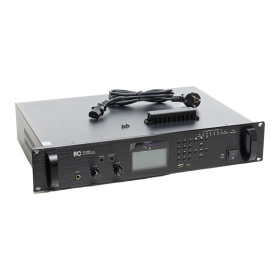
IP NETWORK PA SYSTEM
■ T-7760B/77120B/77240B/77350B/77500B/77650B
■ IP AMPLIFIER
MIC
MIC
Please follow the instructions in this manual to obtain the optimum results from this unit.
We also recommend that you keep this manual handy for future reference.
IP
T-77240B
IP AMPLIFIER
BASS
TREBLE
MIC
AUX
5
5
4
6
4
6
3
7
3
7
2
8
2
8
1
9
1
9
0
10
0
10
T-77500B
IP AMPLIFIER
BASS
TREBLE
MIC
AUX
5
5
4
6
4
6
3
7
3
7
2
8
2
8
1
9
1
9
0
10
0
10
OWNER'S MANUAL
★
OUTPUT LEVEL
●
FINE
2
4
6
1
2
3
IR
4
5
6
7
8
9
USB
OUTPUT LEVEL
FINE
2
4
6
1
2
3
IR
4
5
6
7
8
9
USB
8
10 12
PROT
POWER
ON
OFF
8
10 12
PROT
POWER
ON
OFF
Advertisement
Table of Contents

Related Manuals for ITC T-7760B


Summary of Contents for ITC T-7760B
- Page 1 IP NETWORK PA SYSTEM ■ T-7760B/77120B/77240B/77350B/77500B/77650B ■ IP AMPLIFIER ★ OUTPUT LEVEL ● T-77240B FINE 10 12 PROT POWER IP AMPLIFIER BASS TREBLE OUTPUT LEVEL T-77500B FINE 10 12 PROT POWER IP AMPLIFIER BASS TREBLE OWNER'S MANUAL Please follow the instructions in this manual to obtain the optimum results from this unit.
-
Page 2: Table Of Contents
TABLE OF CONTENTS SAFETY PRECAUTIONS ..................3 APPLICATION ......................5 FEATURES ......................5 NOMENCLATURE AND FUNCTIONS .................6 Front panel ......................6 Rear panel ......................7 5. TERMINAL CONFIGURATION OPERATING INSTRUCTIONS ........8 . WIRING DIAGRAM ....................11 SPECIFICATIONS ....................12... -
Page 3: Safety Precautions
1. SAFETY PRECAUTIONS Be sure to read the instructions in this section carefully before use. Make sure to observe the instructions in this manual as the conventions of safety symbols and messages regarded as very important precautions are included. We also recommend you keep this instruction manual handy for future reference. Safety Symbol and Message Conventions Safety symbols and messages described below are used in this manual to prevent bodily injury and property damage which could result from mishandling. - Page 4 SAFETY PRECAUTIONS When the Unit is in Use When Installing the Unit Do not place heavy objects on the unit as this may Never plug in nor remove the power supply plug cause it to fall or break which may result in with wet hands, as doing so may cause electric personal injury and/or...
-
Page 5: Application
2. APPLICATION The terminal is installed in the storey computer room or sub-control computer room of each broadcas- ting management area. It has a built-in high-fidelity amplifier, and is applicable to program broadcast and local broadcast in halls, corridors, outdoors and other places. 3. -
Page 6: Nomenclature And Functions
4. NOMENCLATURE AND FUCTIONS 4.1 Front panel OUTPUT LEVEL FINE 10 12 PROT POWER BASS TREBLE 9 10 5 6 7 8 1. Local MIC input, Adopting 6.35mm MIC input interface. 2. Volume control of MIC input. 3. Volume control of AUX input. 4. -
Page 7: Rear Panel
4. NOMENCLATURE AND FUCTIONS 4.2 Rear panel BACKUP MAIN AMPLIFIER LINE AMPLIFIER INPUT OUTPUT THREE-WIRE OVERRIDE MUTE SHORT 100V 100V OUTPUT INPUT OUTPUT INPUT LAN IN 9 1011 12 1. AC power input; 2. Case grounding pole; 3. The 100V input port of the standby amplifier is connected to the 100V output terminal of the amplifier;... -
Page 8: Terminal Configuration Operating Instructions
5. TERMINAL CONFIGURATION OPERATING INSTRUCTIONS The terminal needs to be configured before installation, before installation, need make a installation plan including terminal name, terminal IP address, gateway IP address, server IP address, location of terminal installation, and label the information on the terminal to ensure the convenient use of the device. - Page 9 5. TERMINAL CONFIGURATION OPERATING INSTRUCTIONS The configuration steps: Step 1: Connect the terminal and the computer installed with the terminal configuration tool program by the network wire, Plug in the power until the termianl power indicator is on. Step 2: double-click to open the shortcut icon of “ terminal configuration tool”, select the network card first, and left-click the “query”...
- Page 10 5. TERMINAL CONFIGURATION OPERATING INSTRUCTIONS Step 5: If multiple terminals are in the same network segment, you only need to modify the IP address of one terminal, it is needed to click on the terminal in the queried terminals list, then cancel the choice of broadcast on the left interface, modify the IP address and click for configuration.
-
Page 11: Wiring Diagram
6. WIRING DIAGRAM SIGNAL CLIP PROT TEMP POWER VOLUME Power amplifier STANDBY ALARM MODE PLAY RECORD PLAY REC in PLAY SIREN START STOP Emergency alarm device POWER OPEN PLAY STOP PREVIOUS NEXT CLOSE CD/MP3/radio and other audio source devices BACKUP MAIN AMPLIFIER AMPLIFIER... -
Page 12: Specifications
7. SPECIFICATIONS T-7760B T-77120B T-77240B Model RJ 45 Network Interface 100Mbps Transmission Speed TCP/IP, UDP Communication Protocol Audio Format 16 digit stereo CD sound level Audio Mode 8K~48KHz Sampling Rate 8K~512Kbps Bit Rate EMC Input Sensitivity 775mV (unbalance) 350mV (unbalance) - Page 13 7. SPECIFICATIONS T-77350B T-77500B T-77650B Model RJ 45 Network Interface 100Mbps Transmission Speed TCP/IP, UDP Communication Protocol Audio Format 16 digit stereo CD sound level Audio Mode 8K~48KHz Sampling Rate 8K~512Kbps Bit Rate EMC Input Sensitivity 775mV (unbalance) 350mV (unbalance) AUX Input Sensitivity 5mV (unbalance) MIC Input Sensitivity...
- Page 14 Version 0.1...
Need help?
Do you have a question about the T-7760B and is the answer not in the manual?
Questions and answers