Table of Contents
Advertisement
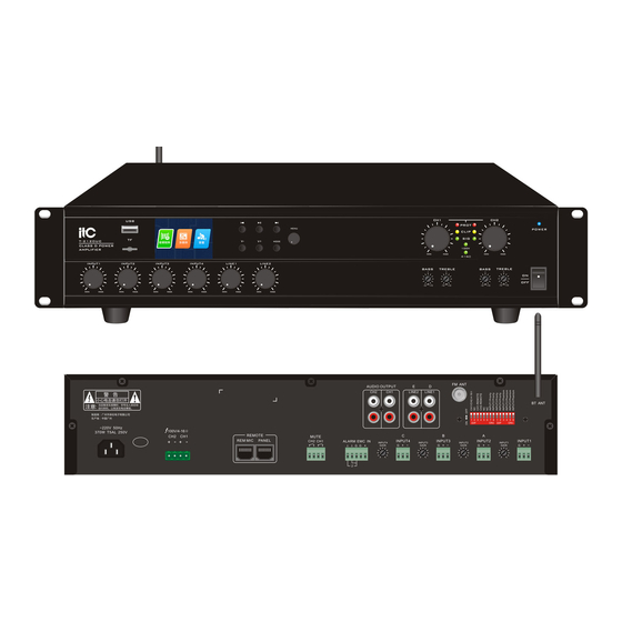
USB
TF
T-4240UC
CLASS D POWER
AMPLIFIER
INPUT1
INPUT2
INPUT3
INPUT4
MIN
MAX
MIN
MAX
MIN
MAX
MIN
Please follow the instructions in this manual to obtain the optimum results from this unit.
We also recommend that you keep this manual handy for future reference.
PUBLIC ADDRESS SYSTEM
CLASS D POWER AMPLIFIER
CH1
PROT
MENU
V
V+
MODE
MIN
MAX
LINE1
LINE2
dB
dB
-10
+10
-10
+10
MAX
MIN
MAX
MIN
MAX
T-4120UC/T-4240UC
CH2
CH3
CH4
PROT
CLIP
CLIP
SIG
SIG
100V
100V
MIN
MAX
MIN
MAX
MIN
MAX
4-16
Ω
4-16
Ω
dB
dB
dB
dB
dB
dB
-10
+10
-10
+10
-10
+10
-10
+10
-10
+10
-10
+10
POWER
Advertisement
Table of Contents


Need help?
Do you have a question about the T-4120UC and is the answer not in the manual?
Questions and answers