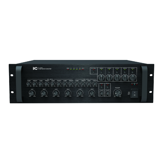
ITC TI-120S Operation Manual

ITC TI-120S Operation Manual

Mixer zone amplifier

Advertisement

TI-120S
MIXER ZONE AMPLIFIER
MIC LEVEL
BASS
TREBLE
BASS
TREBLE
10
10
10
10
10
10
10
MIC1
MIC2
MIN
MAX
MIN
MAX
Please follow the instructions in this manual to obtain the optimum results from this unit.
We also recommend that you keep this manual handy for future reference.
PUBLIC ADDRESS SYSTEM
MIXER ZONE AMPLIFIER
PROT
0
2
4
8
CLIP
LINE LEVEL
BASS
TREBLE
BASS
TREBLE
BASS
TREBLE
BASS
10
10
10
10
10
10
10
10
10
10
10
10
10
10
10
MIC3
MIC4
LINE1
MIN
MAX
MIN
MAX
MIN
MAX
MIN
ALL CALL
ZONE1
ZONE2
ZONE3
ZONE4
ZONE5
3
4
3
4
3
4
3
4
3
2
5
2
5
2
5
2
5
2
1
6
1
6 1
6 1
6 1
TREBLE
SIREN
CHIME
DC PWR
10
10
MASTER
LINE2
VOLUME
VOLUME
ON
OFF
MIN
MAX
MIN
MAX
MAX
MIN
MAX
TI-120S
TI-240S
TI-350S
4
5
6
AC

Advertisement

Table of Contents
loading
Need help?

Need help?

Do you have a question about the TI-120S and is the answer not in the manual?

Questions and answers

Subscribe to Our Youtube Channel

Summary of Contents for ITC TI-120S

  • Page 1 PUBLIC ADDRESS SYSTEM TI-120S TI-240S TI-350S MIXER ZONE AMPLIFIER TI-120S PROT CLIP ALL CALL ZONE1 ZONE2 ZONE3 ZONE4 ZONE5 MIXER ZONE AMPLIFIER MIC LEVEL LINE LEVEL BASS TREBLE BASS TREBLE BASS TREBLE BASS TREBLE BASS TREBLE BASS TREBLE SIREN CHIME...
  • Page 2: Table Of Contents

    TABLE OF CONTENTS 1. SAFETY PRECAUTIONS ..................2 2. GENERAL DESCRIPTION ..................4 3. FEATURES .......................4 4. NOMENCLATURE AND FUNCTIONS 4.1 Front Panel ......................5 4.2 Rear Panel......................6 5. OPERATING ......................8 6. APPLICATIONS ...................... 9 7.SPECIFICATIONS ....................10 8. BLOCK DIAGRAM ....................11 9.
  • Page 3: Safety Precautions

    1. SAFETY PRECAUTIONS Be sure to read the instructions in this section carefully before use. Make sure to observe the instructions in this manual as the conventions of safety symbols and messages regarded as very important precautions are included. We also recommend you keep this instruction manual handy for future reference. Safety Symbol and Message Conventions Safety symbols and messages described below are used in this manual to prevent bodily injury and property damage which could result from mishandling.
  • Page 4 When Installing the Unit When Installing the Unit Never plug in nor remove the power supply plug Do not place heavy objects on the unit as this may with wet hands, as doing so may cause electric cause it to fall or break which may result in personal shock.
  • Page 5: General Description

    2. GENERAL DESCRIPTION The Mixer Zone Amplifier series is equiped with priority function. They are designed to suit all PA system application in schools ,home ,offices and stores. 3. FEATURES 5 zone output and 5 zone separate volume control Built-in siren.
  • Page 6: Nomenclature And Functions

    4. NOMENCLATURE AND FUNCTIONS 4.1 FRONT PANEL PROT CLIP ALL CALL ZONE1 ZONE2 ZONE3 ZONE4 ZONE5 MIC LEVEL LINE LEVEL BASS TREBLE BASS TREBLE BASS TREBLE BASS TREBLE BASS TREBLE BASS TREBLE SIREN CHIME DC PWR MASTER MIC1 MIC2 MIC3 MIC4 LINE1 LINE2...
  • Page 7: Rear Panel

    NOMENCLATURE AND FUCTIONS 4.2 REAR PANEL OUTPUT ZONE 1 ZONE 2 ZONE 3 ZONE 4 ZONE 5 REMOTE 100V CHIME ACTIVE 100V 100V 100V 100V 100V ~ 230V 50Hz T3.15AL 250V 2 TONE 4 TONE XLR BAL PRIORITY 1-GND +48V PHANTOM +48V PHANTOM +48V PHANTOM +48V PHANTOM...
  • Page 8 NOMENCLATURE AND FUCTIONS Pin 1: Remote amplifier input signal hot(+) Pin 2: Remote amplifier input signal cold(-) Pin 3: Signal ground Pin 4: Remote control 1(Speaker 1) Pin 5: Remote control 2(Speaker 2) Pin 6: Remote control 3(Speaker 3) Pin 7: Remote control 4(Speaker 4) Pin 8: Remote control 5(Speaker 5) Pin 9: Remote control ground Pin 10: DC +24V...
  • Page 9: Operating

    5. OPERATING CONNECTING SPEAKERS Before connecting speakers, disconnect the AC power cable. Note the proper connecting terminals as shown Below. Make certain that the total impe- dance is not less than the rated impedance indicated. CONNECTING HIGH-VOLTAGE DISTRIBUTED SPEAKER SYSTEMS When connecting speaker system in parallel, you can connect speakers with a total rated input of up to 100W.
  • Page 10: Applications

    6. APPLICATIONS...
  • Page 11: Specifications

    7. SPECIFICATIONS TI 350S TI-240S TI-120S RATED OUTPUT POWER (THD 1%) 350W(RMS) 240W(RMS) 120W(RMS) AMPLIFIER SECTION (4OHMS LOAD OUTPUT) SPEAKER ZONE 1~5 OUTPUT 25W 70W MAX 50W MAX 25W MAX INPUT SENSITIVITY/IMPEDANCE 5MV 600 -245MV 5K BAL S/N RATIO Better than 55dB...
  • Page 12: Block Diagram

    8. BLOCK DIAGRAM...
  • Page 13: Dimensional Diagram

    9.DIMENSIONAL DIAGRAM UNIT:mm PROT CLIP ALL CALL ZONE1 ZONE2 ZONE3 ZONE4 ZONE5 MIC LEVEL LINE LEVEL BASS TREBLE BASS TREBLE BASS TREBLE BASS TREBLE BASS TREBLE BASS TREBLE SIREN CHIME DC PWR MASTER MIC1 MIC2 MIC3 MIC4 LINE1 LINE2 VOLUME VOLUME OUTPUT ZONE 1...
  • Page 14 PUBLIC ADDRESS SYSTEM PUBLIC ADDRESS SYSTEM VersionV0.5...

This manual is also suitable for:

Ti-240sTi-350s

Table of Contents