
Related Manuals for KSB Amarex


Summary of Contents for KSB Amarex
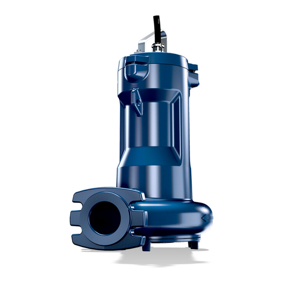
- Page 1 Submersible Motor Pump Amarex Sizes DN 50 to DN 150 60 Hz NEMA Installation/Operating Manual...
- Page 2 All rights reserved. The contents provided herein must neither be distributed, copied, reproduced, edited or processed for any other purpose, nor otherwise transmitted, published or made available to a third party without the manufacturer's express written consent. Subject to technical modification without prior notice. © KSB SE & Co. KGaA, Frankenthal 10/2/2020...
-
Page 3: Table Of Contents
5.3.1 Stationary wet installation ........................ 23 5.3.2 Transportable model for wet installation .................. 29 Electrical system.............................. 30 5.4.1 Information for planning the control system .................. 30 5.4.2 Electrical connection.......................... 33 Commissioning/Start-up/Shutdown.................... 36 Commissioning/start-up .......................... 36 6.1.1 Prerequisites for commissioning/start-up .................. 36 6.1.2 Start-up............................... 36 Amarex 3 of 72... - Page 4 Wiring diagram, motor versions US and YS, star configuration for resin-sealed cable entry.. 63 9.3.2 Wiring diagram, motor versions US and YS, star/delta configuration for resin-sealed cable entry .. 64 Flamepaths on explosion-proof motors ...................... 65 Sectional drawings of the mechanical seal .................... 68 Certificate of Decontamination...................... 69 Index .............................. 70 Amarex 4 of 72...
-
Page 5: Glossary
Motor directly fitted to the pump via a flange or a drive lantern Hydraulic system The part of the pump in which the kinetic energy is converted into pressure energy Efficiency class to IEC 60034-30: 3 = Premium Efficiency (IE = International Efficiency) Amarex 5 of 72... -
Page 6: General
In the event of damage, immediately contact your nearest KSB service facility to maintain the right to claim under warranty. 1.2 Installation of partly completed machinery To install partly completed machinery supplied by KSB refer to the sub-sections under Servicing/Maintenance. -
Page 7: Symbols
Machine damage In conjunction with the signal word CAUTION this symbol indicates a hazard for the machine and its functions. If agreed upon in the scope of supply. Amarex 7 of 72... -
Page 8: Safety
▪ Consult the manufacturer about any use or mode of operation not described in the data sheet or product literature. ▪ Only use the respective impeller types in combination with the fluids described below. Amarex 8 of 72... -
Page 9: Personnel Qualification And Personnel Training
▪ If shutting down the pump does not increase potential risk, fit an emergency stop control device in the immediate vicinity of the pump (set) during pump set installation. Amarex 9 of 72... -
Page 10: Safety Information For Maintenance, Inspection And Installation
▪ Only original spare parts and accessories authorized by the manufacturer must be used for explosion-proof pumps. 2.9.1 Repair Special regulations apply to repair work on explosion-proof pumps. Modifications or alterations of the pump set can affect explosion protection and are only permitted after consultation with the manufacturer. Amarex 10 of 72... -
Page 11: Transport/Storage/Disposal
1. On transfer of goods, check each packaging unit for damage. 2. In the event of in-transit damage, assess the exact damage, document it and notify KSB or the distributor and the insurance company about the damage in writing immediately. -
Page 12: Return To Supplier
Always indicate any safety measures and decontamination measures taken. (ð Section 10, Page 69) NOTE If required, a blank certificate of decontamination can be downloaded from the KSB web site at: www.ksb.com/certificate_of_decontamination 3.5 Disposal WARNING Fluids, consumables and supplies posing a health hazard Hazard to persons and the environment! ▷... - Page 13 Contact your local waste disposal partner for returns. If the used electrical or electronic equipment contains personal data, the operator is responsible for deleting it before the equipment is returned. Amarex 13 of 72...
-
Page 14: Description Of The Pump (Set)
D 1 0 0 - 2 3 0 See name plate and data sheet See data sheet Table 7: Designation key Position Code Description Pump type Amarex Impeller type D-max Open two-vane impeller F-max Free-flow impeller 6-12 Size Nominal discharge nozzle diameter [mm]... -
Page 15: Name Plate
MADE IN FRANCE ZN 3826 - M 74 MADE IN FRANCE ZN 3826 - M 66 Fig. 1: Name plate (example) a) Standard pump set, b) Explosion-proof pump set Description KSB order number Flow rate Maximum fluid and ambient temperature Enclosure Rated power Rated speed... -
Page 16: Installation Types
P7: chain and shackle Guide cable arrangement P1: pump P4: installation parts for guide cable arrangement, installation depth = 14.8 ft P5: claw P7: chain and shackle Standard for impeller type D-max, optional for impeller type F-max Amarex 16 of 72... - Page 17 P1: pump P4: installation parts for twin guide rail arrangement P5: claw and adapter P7: chain and shackle Table 9: Installation type P, transportable wet-installed model Installation type Description P1: pump P6: pump foot P7: chain and shackle Amarex 17 of 72...
-
Page 18: Configuration And Function
▪ Pump set complete with connection cables ▪ Claw with sealing elements and mounting elements ▪ Mounting bracket with mounting elements ▪ Base elbow with mounting elements ▪ Guiding equipment The guide rails are not included in the scope of supply. Amarex 18 of 72... -
Page 19: Dimensions And Weights
▪ Lifting rope / lifting chain NOTE A separate name plate is included in KSB's scope of supply. Attach this name plate in a clearly visible position outside the place of installation, e.g. at the control panel, pipeline or mounting bracket. -
Page 20: Installation At Site
Impermissible solid objects (tools, screws/bolts or similar) in the pump sump/inlet tank during pump start-up Personal injury and damage to property! ▷ Check the pump sump/inlet tank for impermissible solid objects before flooding, and remove, if necessary. Amarex 20 of 72... -
Page 21: Checks To Be Carried Out Prior To Installation
ð The lubricant level must be 0.12 ft [38 mm] below the filler opening. 3. If the lubricant level is lower, top up the lubricant chambers through the filler opening until the indicated level M is reached. 4. Close screw plug 903.03 with joint ring 411.03. Observe the tightening torques. Amarex 21 of 72... -
Page 22: Checking The Direction Of Rotation
4. Disconnect the pump set from the power supply and make sure it cannot be switched on unintentionally. 5.3 Installing the pump set Always refer to and comply with the general arrangement drawing/outline drawing when installing the pump set. Amarex 22 of 72... -
Page 23: Stationary Wet Installation
Fig. 5: Dimensions Table 10: Chemical anchor dimensions Size [″] [″] [″] [″] [″] [ft lb] × l × 5 14,75 ″ × 7 ″ 44,25 Size [mm] [mm] [mm] [mm] [mm] [Nm] × l M10 × 130 M16 × 190 SW = Width across flats Amarex 23 of 72... - Page 24 ▷ In the case of longer riser pipes, fit a swing check valve to prevent the pump from excessively running in reverse after it is switched off. Choose the position of the swing check valve to allow proper venting. Fig. 6: Permissible flange loads Amarex 24 of 72...
- Page 25 3. Fasten threaded bolt 904 with the pre-assembled clamping arrangement to the mounting bracket with nut 920.36. Do not tighten nut 920.36 too much; allow sufficient play for subsequently tensioning the guide cable. Nominal flange diameter Amarex 25 of 72...
- Page 26 NOTE The guide rails are not included in KSB's scope of supply. Select guide rail materials which are suitable for the fluid handled or as specified by the operator.
- Page 27 6. Tighten nuts 920.01. Fig. 10: Fitting 2 guide rails This expands the clamping sleeves so that they clamp the rails at the inside rail diameter. 7. Secure nut 920.01 with a second nut. To DIN 2440/2442/2462 or equivalent standards Amarex 27 of 72...
- Page 28 Attach the lifting chain with shackle or the lifting rope to the pump set handle. This attachment point achieves a forward inclination of the pump set towards the discharge nozzle, which allows the pump claw to hook onto the base elbow. Amarex 28 of 72...
-
Page 29: Transportable Model For Wet Installation
The pump set attaches itself to base elbow 72-1. 2. Attach the lifting chain / lifting rope to hook 59-18 at the mounting bracket. 5.3.2 Transportable model for wet installation Before installing the pump set, fit the three pump feet and foot plate if applicable. Amarex 29 of 72... -
Page 30: Electrical System
1. Protect the pump set against overloading by a thermal time-lag overload protection device in accordance with IEC 60947 and local regulations. 2. Set the overload protection device to the rated current specified on the name plate. Amarex 30 of 72... - Page 31 No modifications are required on the power/control cable of the submersible motor pump. Suitable analyzing devices must be selected. To monitor the leakage sensor inside the motor using a special relay available from KSB is recommended. 5.4.1.4 Sensors DANGER...
- Page 32 The pump set features sensors that avoid hazards and damage to the pump set. Measuring transducers are required for analyzing the sensor signals supplied. Suitable devices for 230 V AC can be supplied by KSB. NOTE Reliable and safe operation of the pump within the scope of our warranty is only possible if the sensor signals are properly analyzed as stipulated in this manual.
-
Page 33: Electrical Connection
▷ Never move the power cables at temperatures below -13 °F [-25 °C]. ▷ Never kink or crush the power cables. ▷ Never lift the pump set by the power cables. ▷ Adjust the length of the power cables to the site requirements. Optional Amarex 33 of 72... - Page 34 3. If necessary, adjust the length of the power cable to the site requirements. 4. After shortening the cable, correctly re-affix the markings on the individual cores at the cable end. Potential equalization The pump set has not got an external PE connection (risk of corrosion). Amarex 34 of 72...
- Page 35 5 Installation at Site DANGER Touching the pump set during operation Electric shock! ▷ Make sure that the pump set cannot be touched during operation. Amarex 35 of 72...
-
Page 36: Commissioning/Start-Up/Shutdown
Damage to the pump set! ▷ Do not re-start the pump set before it has come to a standstill. ▷ Never start the pump set while the pump is running in reverse. ü The fluid level is sufficiently high. Amarex 36 of 72... -
Page 37: Operating Limits
▷ Never operate an explosion-proof pump (set) outside the specified range. The maximum permissible deviation in supply voltage is ±10 % of the rated voltage. The voltage difference between the individual phases must not exceed 1 %. Amarex 37 of 72... -
Page 38: Operation On A Frequency Inverter
▷ Never allow the fluid level to drop below the specified minimum. The pump set is ready for operation when the fluid level has reached dimension R3, R3´, R4 or R4´ as a minimum (see outline drawing). Amarex 38 of 72... -
Page 39: Shutdown/Storage/Preservation
Fluids handled, consumables and operating supplies which are hot or pose a health hazard Risk of personal injury! ▷ Observe all relevant laws. ▷ When draining the fluid take appropriate measures to protect persons and the environment. ▷ Decontaminate pumps which handle fluids posing a health hazard. Amarex 39 of 72... -
Page 40: Returning To Service
Risk of personal injury from moving parts or escaping fluid! ▷ As soon as the work is completed, re-install and/or re-activate any safety- relevant devices and protective devices. NOTE On pumps/pump sets older than 5 years we recommend replacing all elastomer seals. Amarex 40 of 72... -
Page 41: Servicing/Maintenance
Risk of injury by moving components and shock currents! ▷ Make sure that the pump set cannot be started up unintentionally. ▷ Always make sure the electrical connections are disconnected before carrying out work on the pump set. Amarex 41 of 72... -
Page 42: Maintenance/Inspection
(set) with a minimum of maintenance expenditure and work. NOTE All maintenance work, service work and installation work can be carried out by KSB Service or authorized workshops. Find your contact in the attached "Addresses" booklet or on the Internet at "www.ksb.com/contact". -
Page 43: Inspection Work
ð The insulation resistance of the core ends to chassis ground must not be lower than 1 MΩ. If the resistance measured is lower, power cable and motor resistance must be measured separately. Disconnect the power cable from the motor for this purpose. Amarex 43 of 72... -
Page 44: Lubrication And Lubricant Change
7.2.2.1.2 Lubricant quality The lubricant chamber is filled at the factory with environmentally friendly, non-toxic lubricant of medical quality (unless otherwise specified by the customer). The following lubricants can be used to lubricate the mechanical seals: Amarex 44 of 72... - Page 45 0.77 0.73 0.77 0.73 1.11 1.05 1.11 1.05 1.11 1.05 1.11 1.05 1.11 1.05 1.11 1.05 1.11 1.05 1.11 1.05 1.11 1.05 1.11 1.05 1.11 1.05 1.11 1.05 1.11 1.05 1.11 1.05 1.11 1.05 1.11 1.05 Amarex 45 of 72...
- Page 46 Liquid spurting out when the lubricant chamber is opened at operating temperature! ▷ Open the screw plug of the lubricant chamber very carefully. 3. Remove screw plug 903 with joint ring 411. Drain off the lubricant. Amarex 46 of 72...
- Page 47 Table 22: Lubricant level Motor version Efficiency class Number Lubricant quantity of poles [inch] [ml] 1.69 1.69 1.69 1.69 1.69 1.69 1.69 1.69 1.69 1.69 1.81 1.81 1.81 1.81 1.81 1.81 1.81 1.81 1.81 1.81 1.81 1.81 Amarex 47 of 72...
-
Page 48: Drainage/Cleaning
Risk of personal injury! ▷ Always have repair work and maintenance work performed by specially trained, qualified personnel. WARNING Hot surface Risk of personal injury! ▷ Allow the pump set to cool down to ambient temperature. Amarex 48 of 72... -
Page 49: Preparing The Pump Set
Observe the safety instructions and information. For dismantling and reassembly observe the general assembly drawing. In the event of damage you can always contact KSB Service. DANGER Insufficient preparation of work on the pump (set) Risk of injury! ▷... -
Page 50: Removing The Mechanical Seal And Motor Section
Fig. 21: Forcing screw NOTE The forcing screw is not included in the scope of supply. It can be ordered separately from KSB. 7.4.4 Removing the mechanical seal and motor section NOTE Special regulations apply to repair work on explosion-proof pump sets. -
Page 51: Reassembling The Pump Set
100. Then fasten discharge cover 163 with screws 914.74. 3. Guide the pump-end mechanical seal 433.02 onto shaft 210. For special mechanical seals with covered spring, tighten the socket head cap screw at the rotating assembly before fitting the impeller. Observe installation dimension Amarex 51 of 72... - Page 52 ð Verify the minimum length of the eyebolt, see the corresponding table. ð If a different bolt length is used, insert shim(s) to establish contact with the impeller. Not included in KSB's scope of supply Amarex 52 of 72...
-
Page 53: Reassembling The Motor Section
Before reassembling the motor section, check that all joints relevant to explosion protection (flamepaths) are undamaged. Any components with damaged flamepaths must be replaced. Only use original spare parts made by KSB for explosion-proof pump sets. Observe the flamepath positions specified in the Annex (Flamepaths on explosion-proof motors). -
Page 54: Checking The Connection Of Motor/Power Supply
Refer to the name plate for all data. Also supply the following data: ▪ Part No. and description (ð Section 9.1, Page 58) ▪ Quantity of spare parts ▪ Shipping address ▪ Mode of dispatch (freight, mail, express freight, air freight) Amarex 54 of 72... -
Page 55: Recommended Spare Parts Stock For 2 Years' Operation To Din 24296
Part number Description 99-19 550.23 Disc Shim 903.03 Screw plug 904.15 Grub screw 914.01/.04/.10/.16/.20/.26/.74/.83 Hexagon socket head cap screw 411.03 Joint ring 412.01/.02/.07/.15/.16/.47 O-ring 433.01/.02 Mechanical seal 932.03 Circlip 320, 321.01 Rolling element bearing 932.02/.04 Circlip Amarex 55 of 72... -
Page 56: Trouble-Shooting
If problems occur that are not described in the following table, consultation with KSB Service is required. A Pump is running but does not deliver... - Page 57 ✘ - Motor has been tripped Have cause determined and eliminated by by leakage monitor. qualified and trained personnel. ✘ ✘ - For star-delta starting: Motor runs in star Check star-delta contactor. configuration only Amarex 57 of 72...
-
Page 58: Related Documents
9 Related Documents 9 Related Documents 9.1 General assembly drawings with list of components 9.1.1 General assembly drawing UG1800009 Fig. 25: General assembly drawing, F-max impeller Amarex 58 of 72... - Page 59 Grub screw 412.01/.02/.15/.16/.47 O-ring 914.01/.10/.16/.26/.74/.83 Hexagon socket head cap screw 433.01/.02 Mechanical seal 932.02/.03/.04/.08 Circlip 550.23 Disc 970.02 Label/plate Rivet Only used for version with impeller type D-max Only used for version with impeller type F-max Amarex 59 of 72...
-
Page 60: Exploded Views With Lists Of Components
9 Related Documents 9.2 Exploded views with lists of components 9.2.1 Exploded view UG1800384 Fig. 27: Exploded view, Amarex F-max Amarex 60 of 72... - Page 61 9 Related Documents UG1800041 Fig. 28: Exploded view, Amarex D-max Table 31: List of components Part No. Description Part No. Description Casing Ring Intermediate casing Disc Suction cover Grooved pin Feet 69-6 Temperature sensor Shaft 69-16 Humidity sensor 23-7 Impeller body 81-2...
- Page 62 9 Related Documents Part No. Description Part No. Description Joint ring Screw plug 412.01/.02/.03/.04/.05 O-ring Grub screw 433.01/.02 Mechanical seal 914.01/.02/.03/.04/.06 Hexagon socket head cap screw Mating ring carrier 932.01/.02/.03/.04 Circlip 59-17 Shackle Amarex 62 of 72...
-
Page 63: Wiring Diagrams
Fig. 29: Wiring diagram, motor versions US and YS, star configuration for resin-sealed cable entry Shielded cable option Ⓐ Motor temperature Ⓕ Monitoring of leakage inside the motor (optional) (*) Power cable with leakage sensor: AWG 15-8 Amarex 63 of 72... -
Page 64: Wiring Diagram, Motor Versions Us And Ys, Star/Delta Configuration For Resin-Sealed Cable Entry
Fig. 30: Wiring diagram, motor versions US and YS, star/delta configuration for resin- sealed cable entry Shielded cable option Motor temperature Ⓐ Ⓕ Monitoring of leakage inside the motor (optional) Power cable: AWG 15-12 or AWG 13-12 (*) Power cable with leakage sensor Amarex 64 of 72... -
Page 65: Flamepaths On Explosion-Proof Motors
Tolerance ISO outside diameter Tolerance in µm inside diameter to Maximum DIN ISO 286/2 Minimum Tolerance in µm outside diameter Maximum to DIN ISO 286/2 Minimum Tolerance in µm inside diameter Maximum Minimum Tolerance in µm outside diameter Maximum Minimum Amarex 65 of 72... - Page 66 Tolerance ISO outside diameter Tolerance in µm inside diameter Maximum to DIN ISO 286/2 Minimum Tolerance in µm outside diameter Maximum to DIN ISO 286/2 Minimum Tolerance in µm inside diameter Maximum Minimum Tolerance in µm outside diameter Maximum Minimum Amarex 66 of 72...
- Page 67 Tolerance ISO outside diameter Tolerance in µm inside diameter Maximum to DIN ISO 286/2 Minimum Tolerance in µm outside diameter Maximum to DIN ISO 286/2 Minimum Tolerance in µm inside diameter Maximum Minimum Tolerance in µm outside diameter Maximum Minimum Amarex 67 of 72...
-
Page 68: Sectional Drawings Of The Mechanical Seal
433.02 Mechanical seal (bellows-type mechanical seal) 433.01 932.03 433.02 UG1796735 Mechanical seal with covered springs 433.01 Mechanical seal (bellows-type mechanical seal) 932.03 Circlip 433.02 Mechanical seal (mechanical seal with covered springs, HJ) 433.01 932.03 433.02 UG1796735 Amarex 68 of 72... -
Page 69: Certificate Of Decontamination
We confirm that the above data and information are correct and complete and that dispatch is effected in accordance with the relevant legal provisions....................................Place, date and signature Address Company stamp Required fields Amarex 69 of 72... -
Page 70: Index
Electromagnetic compatibility 31 Permissible flange loads 24, 25 Event of damage 6 Piping 24 Ordering spare parts 54 Exploded view Preservation 11 Amarex D-max, version YS 61 Product code 14 Amarex F-max, version YS 60 Explosion protection 22, 32, 34, 37, 38, 41, 50, 53 Reassembly 49 Return to supplier 12 Faults Returning to service 40... - Page 72 KSB SE & Co. KGaA Johann-Klein-Straße 9 • 67227 Frankenthal (Germany) Tel. +49 6233 86-0 www.ksb.com...
Need help?
Do you have a question about the Amarex and is the answer not in the manual?
Questions and answers