Table of Contents
Advertisement
Advertisement
Table of Contents

Subscribe to Our Youtube Channel
Related Manuals for Volvo EC60E


Summary of Contents for Volvo EC60E
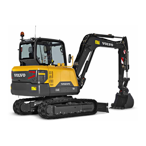
- Page 1 VOLVO CONSTRUCTION EQUIPMENT operator’s manual ec60E...
-
Page 2: Foreword
Safety when servicing change data and equipment, as well as the service and maintenance instructions, without prior notice. Maintenance Specifications Alphabetical index Ref. No. 20044040-C The original language is English. Original instructions. 2018.05 Copyright © 2018, Volvo Construction Equipment. All rights reserved. - Page 3 Foreword Safety regulations The machine operator is responsible for being aware of and complying with the relevant, legally prescribed, national and regional safety instructions. The safety instructions in this operator's manual are applicable only in cases where no legislated safety instructions are in force. DANGER The safety symbol combined with this signal word indicates a will result in death...
-
Page 4: Identification Numbers
Machine PIN (Serial number) Engine Main pump Swing motor Track motor Main control valve • Please send any comments about the Operator's Manual to om@volvo.com. • Open source code used in this product can be got from the following web site. (http:// webdoc.volvo.co.kr/exc-oss) -
Page 6: Table Of Contents
Table of contents Table of contents Foreword ..........1 Identification numbers ........3 Presentation ........... 9 Machine view ..........16 CE-marking, EMC-directive ......18 Communication equipment, installation ..23 Safety components ........24 Product plates ..........25 Information and warning decals ....27 Instrument panels ......... - Page 7 Table of contents Operating techniques ......173 Whole-body vibrations ........ 174 Rules for digging ......... 176 Working within dangerous areas ....179 Attachments ..........191 Attachments, connecting and disconnecting ..........194 Attachment brackets ........201 Mechanical attachment bracket ....202 Buckets ............
- Page 8 Table of contents Specifications ........298 Recommended lubricants ......298 Fuel system ..........304 Service capacities and change intervals ..309 Engine ............311 Electrical system ......... 312 Cab ............. 314 Hydraulic system ........315 Machine weights ......... 317 Ground pressure ......... 318 Dimensions ..........
-
Page 10: Presentation
Presentation Presentation V1157220 Intended use The machine is intended to be used under normal conditions for the applications described in this manual. If it is used for other purposes or in potentially dangerous environments, for example explosive atmosphere, flammable environment or areas with dust containing asbestos and so on, special safety regulations must be followed and the machine be equipped for such use. - Page 11 Presentation Engine The new engine which provide excellent performance is equipped with a four-cylinder, vertical, electronic controlled high pressure fuel injectors, in-line turbo charger and water cooled diesel engine type. This engine fully meets the demands of the latest EU Stage IV / US Tier 4 final emissions regulations.
- Page 12 Presentation Electrical system The electrical system consists of engine starting system, charging system, machine monitoring system, engine / pump control system and air conditioning system. The machine is equipped with a high capacity electrical system well protected. Waterproof double-lock harness plugs are used to secure corrosion-free connections.
- Page 13 Volvo Engineering Department. This department will decide whether the alteration may cause the approval to become void.
- Page 14 Presentation Hydraulic system The machine is equipped with a flow control system with variable flow. With this system, the working pump can deliver flow according to demand. A variable flow from the pump allows precision work even with high engine speed. Track motor and gearbox Each track is powered by an automatic two-speed shift track motor.
- Page 15 The machine is equipped with a software system, which records various information about the machine and this information is transferred from the machine to Volvo and used by Volvo and its authorized workshops in the product development process and for possible malfunction detection.
- Page 16 This helps to eliminate unauthorized machine use and theft. For further information, contact a Volvo Construction Equipment dealer. The CareTrack system transmits data, in the same way a mobile phone does, with a maximum output rate of 10 W.
-
Page 17: Machine View
Presentation Machine view Machine view V1157221 1 Cab 12 Track 2 Boom 13 Idler 3 Dipper arm cylinder 14 Bottom roller 4 Dipper arm 15 Front cover 5 Bucket cylinder 16 Upper roller 6 Link 17 Track motor and gearbox 7 Bucket 18 Counterweight 8 Boom cylinder... - Page 18 Presentation Machine view V1157222 23 Rear view camera 27 Engine oil filling port 24 Engine air cleaner 28 Radiator & Hydraulic oil cooler 25 Diesel particulate filter 29 Coolant expansion tank 26 Fuel filter...
-
Page 19: Ce-Marking, Emc-Directive
As proof that the requirements are met, the machine is supplied with an EU Declaration of Conformity, issued by Volvo CE for each separate machine. This EU declaration also covers attachments manufactured by Volvo CE. The documentation is a valuable document, which should be kept safe and retained for at least ten years. - Page 20 Presentation CE-marking, EMC-directive EU EMC Directive The electronic equipment of the machine may in some cases cause interference to other electronic equipment, or suffer from external electromagnetic interference, which may constitute safety risks. The EU EMC directive about "Electromagnetic compatibility", 2014/30/EC, provides a general description of what demands can be made on the machine out of a safety point of view, where permitted limits have been determined and given...
- Page 21 Below you find a generic copy of the Declaration of Conformity. NOTE! The Declaration of Conformity is only applicable in the European Union. EC DECLARATION OF CONFORMITY FOR MACHINERY (IIA) Volvo Group Korea Co., Ltd. Seongsan-gu, Changwon-si, Gyeongsangnam-do, Korea 51710 hereby declares that the product: Make: Volvo Construction Equipment...
- Page 22 Presentation CE-marking, EMC-directive Signature of authorized issuer and person authorized to compile the technical file established in the community: ............................Signature / block capitals ............................Position or title ............................Address and Date of issue Signature of authorized issuer on behalf of manufacturer (only if applicable) ............................
- Page 23 Measured sound power value, in dB(A): XXX Guaranteed sound power value, in dB(A): XXX The Volvo EC/ECR/EW/FCXXXX conforms to directive 2000/14/EC Annex VI Internal control of production with assessment of technical documentation and periodical checking, under the supervision of the Notified Body 1067 Manufactured at: Volvo Group Korea Co., Ltd.
-
Page 24: Communication Equipment, Installation
Communication equipment, installation NOTICE All installation of optional electronic communication equipment must be performed by trained professionals and in accordance with the Volvo Construction Equipment instructions. Protection against electromagnetic interference This machine has been tested in accordance with EU directive 2014/30/EC governing electromagnetic interference. -
Page 25: Safety Components
(PIN-number) when ordering spare parts. Position of PIN-plate, see section "Product plates". Your Volvo dealer always has up-to-date spare part information that is updated at regular intervals via the information system PROSIS. Safety-classified machine and spare parts... -
Page 26: Product Plates
Presentation Product plates Product plates Please refer to the figure below to locate the product plate, engine plate and attachment plates. Always use the Product Identification Number (PIN) provided on the vehicle and/or engine plates for troubleshooting purposes and/or when ordering spare parts. - Page 27 Presentation Product plates Bucket The nameplate is attached on the top of the bucket and indicates the bucket model order number, serial number, supplier code, rated capacity, weight, cutting width, tooth part number and adapter part number. The nameplate is attached on the inside of the cab and indicates the product number, machine model, cab serial number, ROPS certificate number, maximum machine mass and international...
-
Page 28: Information And Warning Decals
Presentation Information and warning decals Information and warning decals Information and warning decals are affixed to the machine on strategic locations to remind operators and maintenance personnel specific safety precautions. All decals are not installed on all machines, as they are market and machine dependent. The decals must be kept free from dirt, so that they can be read and understood. - Page 29 Presentation Information and warning decals V1079479 V1079477 1 WARNING! Read the Operator's 2 WARNING! Hot surfaces and rotating manual. (Spare part number in USA: parts 13935003) V1065357 V1065344 3 WARNING! High pressure, do not 4 WARNING! Hot and pressurised unscrew the recoil spring when coolant when opening radiator cap.
- Page 30 Presentation Information and warning decals V1065364 V1077432 7 Sound power level outside machine 8 Lifting point V1065381 V1129244 9 Tie-down point 10 Emergency exit V1065366 V1079484 11 Coolant information – read the 12 WARNING! No smoking when fuel 274 . Operator's manual.
- Page 31 Presentation Information and warning decals V1077433 V1079483 13 WARNING! Do not start the engine. 14 WARNING! Risk of electrical shock, corrosive burns and explosion – read the Operator's manual. V1065370 V1065355 15 WARNING! Lock the front window. 16 Machine position when checking hydraulic oil level.
- Page 32 Presentation Information and warning decals V1065343 V1079478 18 WARNING! High voltage, keep safe 19 WARNING! Do not step on this surface. distance from electrical power lines. (Spare part number in USA: 11026072) V1093043 V1125755 20 WARNING! Before working after 21 Battery disconnect switch. connecting and disconnecting attachment –...
- Page 33 Presentation Information and warning decals V1079481 V1077503 24 WARNING! Dozer blade lever. 25 WARNING! Operating the optional attachment. Equipment may strike the cab or machine. V1077504 V1077505 26 Notice attachment 27 Notice attachment ISO VG #68 V1077506 V1065371 28 Greasing interval – read the Operator's 29 Type of hydraulic oil filled at factory manual.
- Page 34 Presentation Information and warning decals V1077495 326 . 32 Instruction for lifting machine 33 Lifting capacity. See page V1159072 V1079480 34 Lever and pedal functions (optional). 35 WARNING! Risk of explosion – read 293 . the Operator's manual. See page MAX 500 ppm SULFUR LONG LIFE HYDRAULIC OIL V1129275...
-
Page 35: Instrument Panels
Instrument panels Instrument panels WARNING Risk of serious injury. Operating the machine without sufficient skills and knowledge of the content in the Operator’s Manual could lead to loss of machine control and could cause serious injuries including death. Carefully read through the Operator’s Manual and learn the warning signs, symbols and operating instructions before attempting to operate the machine. -
Page 36: Instrument Panel, Left
Instrument panels Instrument panel, left Instrument panel, left Interior light switch Attachment quick coupler switch, left (optional equipment) Rotating beacon switch (optional equipment) Air compressor switch (optional equipment) V1159070 Interior light switch Position 0: Cabin light is switched OFF Position 1: Cabin light is switched ON V1065651... - Page 37 Instrument panels Instrument panel, left Attachment quick coupler switch, left This switch has 2 different functions of the attachment quick coupler according to the operating condition. V1140835 Press down 1: Attachment quick coupler, opening control The switch is returned automatically. Press the WARNING switch for more than 0.7 seconds to open the attachment quick coupler.
- Page 38 Instrument panels Instrument panel, left Rotating beacon switch Position 0: Rotating beacon is OFF Position 1: Rotating beacon is ON This switch is used to activate the rotating beacon when the swing system is activated. V1065629 Air compressor switch This switch is used to operate the air compressor. 125 .
-
Page 39: Instrument Panel, Front
Instrument panels Instrument panel, front Instrument panel, front The front instrument panel can be adjusted for better operator comfort. NOTE! Prevent machine damage by taking correct action. Read thoroughly and understand the instructions in this section to familiarize yourself with the front instrument panel before trying to operate the machine. - Page 40 Instrument panels Instrument panel, front Central warning light There are three different types of light. NOTE! If the central warning light flashes or lights up while operating, follow the instructions on the display unit. V1134961 A Check, amber B Warning, red C Information, blue Gauges The gauges are always shown unless a warning...
- Page 41 Instrument panels Instrument panel, front Engine speed Engine speed screen is displayed when the "Menu screen" is not shown in the "Main screen". For main 45 . menu screen, see page The "Engine speed step" selected on "Engine speed control switch" is displayed on an engine speed graph which is a segmented bar graph.
- Page 42 Instrument panels Instrument panel, front CCM (Climate Control Module) CCM segment displays the status of the CCM CLIMATE FLOW (Climate Control Module). This includes temperature setting, fan speed, air flow direction, 1 2 3 4 5 circulation, air conditioning status and automatic V1158194 118 for temperature control function.
- Page 43 Instrument panels Instrument panel, front Indicators Table. Function indicators V1065467 V1158802 Overload indicator Wiper STOP V1158803 V1159064 Dozer float activated Automatic shutdown enabled V1158804 V1158805 Dozer blade enabled Rotator enabled V1159063 V1065465 X1 double acting enabled X1 single acting enabled V1159062 V1159065 Boom swing enabled...
- Page 44 Instrument panels Instrument panel, front Table. Warning indicators V1065467 V1065479 Overload warning (optional equipment) Open attachment quick coupler (optional Stop the lifting operation and reduce the equipment) load. Stop work immediately if the bucket is still attached to the attachment bracket. V1160715 V1065488 Quick coupler engaged...
- Page 45 Instrument panels Instrument panel, front Table. Fixed indicators V1065473 V1065472 Message indicator (fixed position) Pattern changer status (fixed position) V1065474 Pattern changer status (fixed position)
-
Page 46: Display Unit
Initial start sequence is performed as follows. A Volvo logo If the operator turns the ignition switch to the operating position, the Volvo logo on the I-ECU screen lights up for a few seconds. B Daily maintenance The operator can see daily maintenance items once a day. - Page 47 Instrument panels Display unit C Initial camera screen (if installed) All the cameras installed on the machine will be displayed on the I-ECU. The initial camera screen is dismissed by pressing the camera button on the keypad. NOTE! Press the camera button on the keypad for the camera views when operating the machine.
- Page 48 Instrument panels Display unit Main menu MENU The main menu is reached by pressing the SELECT Engine button on the keypad. Hydraulics Scroll the list by using the arrow buttons on the keypad. When a folder is highlighted, its Electrical system subscreens are shown when pressing the SELECT Machine information button.
- Page 49 Display unit DPF soot level: This shows the level of soot that Engine has accumulated within the DPF. DPF soot level NOTE! Contact a workshop authorized by Volvo for 100% 130% 140% detailed information on the soot level. V1147259 DPF Regen progress: This shows the Engine measured value of DPF regeneration progress.
- Page 50 Instrument panels Display unit Regeneration mode: This informs the operator Engine about which regeneration mode is selected at the moment. It also allows the operator to select Regeneration Mode a regeneration mode from 3 different modes. Automatic The operator can select a regeneration mode with the arrow buttons.
- Page 51 Instrument panels Display unit 2 Hydraulics Pump torque setting : This shows the current Hydraulics pump torque using bar graph. Pump torque setting V1158199 3 Electrical system Electrical system Voltage: This shows the measured value of Voltage voltage of the battery. When the bar graph is green, the value is OK, within normal operation High range.
- Page 52 Instrument panels Display unit Work timer: This shows the counted work time. Machine information - Reset work timer: Work time can be reset by Work timer pressing the SELECT button when the "Yes" value is highlighted. Press ESC button to 23 h 30 min "Cancel"...
- Page 53 Instrument panels Display unit 5 Service This subscreen shows the service items with “time remaining” value. Press the SELECT button to check detail information. Engine oil filter : This shows the value for remaining time to next engine oil filter service. - Change interval: This shows the value of Service engine oil filter interval in the unit hours.
- Page 54 Instrument panels Display unit Fuel filter : This shows the value for remaining time for next fuel filter service. - Change interval : This shows the value of fuel Service filter interval with in the unit hours. Fuel filter - Reset time remaining : This shows the value for remaining time for next fuel filter service.
- Page 55 Instrument panels Display unit Hydraulic oil : This shows the value for remaining time to next hydraulic oil service. - Change interval : This shows the value of Service hydraulic oil interval in the unit hours. Hydraulic oil - Reset time remaining : This shows the value for remaining time to next hydraulic oil service.
- Page 56 Instrument panels Display unit Hydraulic oil filter : This shows the value for remaining time to next hydraulic oil filter service. - Change interval : This shows the value of Service hydraulic oil filter interval in the unit hours. Hydraulic oil filter - Reset time remaining : This shows the value for remaining time to next hydraulic oil filter xxxh...
- Page 57 Instrument panels Display unit 6 Setup There are sub-items, "Boom-swing”, “X1”, ”Dozer blade”, “X3”, ” Wiper interval”, “Auto idle time”, ”Auto shutdown”, “Anti-theft system”, “Overload pressure”, “Operating pattern, “Language”, “Units”, “Time/date”, “Display backlight”, and “Keypad backlight” and “Camera position”. Boom-swing This is to preset boom-swing speed and Setup response mode.
- Page 58 Instrument panels Display unit Select work tool : This is to select the X1 tool Setup from the list . When operator push the X1/ boom-swing button on the keypad and then push the selection button on the right operating lever, X1 tool which is selected from list can be activated.
- Page 59 Instrument panels Display unit - HAMMER Hammer Control type: Choose the control type. Name Select the preferred control type using the Hammer arrow buttons. Save the selected item using the SELECT Acting direction button. Use ESC button to cancel without 1 way saving.
- Page 60 - Press the SELECT button to save the name. - Use the ESC button to get out of screen New work tool without save. Enter tool name: VOLVO V1158334 3 Select “Adjust tool setting” and then choose Setup the new tool which is newly created.
- Page 61 Instrument panels Display unit 4 Set the ”Acting direction”, ”Control type”, “LH VOLVO speed” and “RH speed” according to new Name tool. VOLVO Acting direction 2 way Control type Proportional LH speed RH speed Response mode Active V1158336 5 Select “Select work tool” and then choose Setup the new tool which is newly created.
- Page 62 Selected work tool can not be deleted. Select work tool Adjust tool setting Delete Delete setting Hammer Shear VOLVO V1158338 Dozer blade Setup Raising speed : This is to preset raising speed Dozer blade of dozer blade. Lowering speed : This is to preset lowering speed of dozer blade.
- Page 63 Instrument panels Display unit Place the mark at the preferred item from the three (or four) listed with the arrow button. When the SELECT button is pressed, the marked item is set. The screen reverts to the former screen displaying the newly selected item.
- Page 64 Select work tool Follow the steps described below. Adjust tool setting New work tool Enter tool name: VOLVO V1158343 1 Select "New" after entering "X3 ". 2 Enter the name of the tool. - Use the arrow UP and arrow DOWN button to select the characters (A,B...Z,0,1...9).
- Page 65 Setup the new tool which is newly created. Select work tool Adjust tool setting Adjust tool setting Hammer Shear VOLVO V1158344 4 Set the ”Acting direction”, ”Control type”, “LH VOLVO speed” and “RH speed” according to new Name tool. VOLVO...
- Page 66 Setup the new tool which is newly created. Select work tool Adjust tool setting Select work tool Hammer Shear VOLVO V1158346 Wiper interval : Operator can adjust the wiper Setup interval of 1st step. Wiper interval Wiper interval Set wiper interval:...
- Page 67 Instrument panels Display unit Auto shutdown : This is to stop the engine Setup automatically when the machine is not operated 11 for Auto shutdown for a certain period of time. See page detailed information. Anti-theft system: This menu is used for setting Auto shutdown timer up the anti-theft system.
- Page 68 Instrument panels Display unit Read PIN code: This sub-menu allows the machine owner to read the current PIN code. Read PIN code PIN Code: 1 2 3 4 Generate random PIN Set PIN code Service action V1160928 Generate random PIN: This sub-menu allows the machine owner to generate a random PIN Read PIN code New PIN Code:...
- Page 69 Instrument panels Display unit Overload pressure: This is to preset of overload Setup 86 for more information pressure. See page Overload pressure regarding overload warning button on keypad. - Select the preferred pressure value using the arrow buttons. Overload pressure - Save the selected value using the SELECT button.
- Page 70 Instrument panels Display unit Units Setup Two unit systems are displayed: "Metric" and Units "US". The operator can select one of the two using the arrow button and save it by pressing SELECT button. Units The units stored in the I-ECU are as follows; Metric Item Metric...
- Page 71 Instrument panels Display unit Time/Date Setup Time/date Time/date Set time Set date Set time format Set date format V1158486 - Set time : This is for adjusting the time. The Time/date preset clock format is shown in the first row of Set time the screen.
- Page 72 Instrument panels Display unit - Set time format : The items "24h" and "12h" Time/date decide how the I-ECU describes the time, 24- Set time format hour-system or 12-hour-system. Set time format V1158489 - Set date format : The items "yy/mm/dd", "mm/ Time/date dd/yy", and "dd/mm/yy"...
- Page 73 If an abnormal condition is sensed, then the Check at next stop message will display the specific error/failure. Contact a workshop authorized by Volvo for System failure advice, if needed. (Engine system) When pressing the SELECT button to view detail...
- Page 74 - The buzzer sounds two times. - Alarm text is shown for seven seconds and then changes to operating display. - Repair or contact a workshop authorized by Volvo for information. Table. Example of information screen Check at next stop...
- Page 75 - Press SELECT button to obtain more information about the malfunction. - Alarm text is shown until confirmation is performed by pressing ESC button. - Repair or contact a workshop authorized by Volvo for information. Table. Example of check screen Check at next stop...
- Page 76 - The buzzer will sound until the required action has been performed. - The alarm text will be shown until the required action has been performed. - Repair or contact a workshop authorized by Volvo for information. Table. Example of warning screen Stop machine...
- Page 77 CareTrack with anti-theft CareTrack with anti-theft (optional equipment) CareTrack with anti-theft function works by WECU, web portal, Volvo's service tool (Tech Tool), V- ECU, and I-ECU. The anti-theft function is to immobilize the machine according to the following conditions. - Wrong code alarm...
- Page 78 CareTrack portal. Enter owner code Level 2: This is a machine owner PIN code with 6 digits which are set using Volvo's service tool. Level 3: This is a one-time code with 8 digits which are obtained from the CareTrack portal.
- Page 79 Instrument panels Display unit Timefence broken - When the machine owner activates a timefence in the CareTrack portal and the machine is outside the timefence, the timefence broken message appears on the I-ECU. Timefence broken V1137935 - When the machine owner activates a timefence and configures automatic immobilization in the CareTrack portal and the machine is outside the timefence, the timefence broken warning...
- Page 80 Instrument panels Display unit Machine movement - If the machine moves 100 metres without its own power, the WECU detects the machine movement and the machine will be immobilized and WECU sends the warning message to the CareTrack portal. Machine immobilized - After the machine has been immobilized, the warning message will appear on the I-ECU before V1139556...
- Page 81 V1139554 Volvo's service tool. - The active trigger and no coverage counter can be reset using a one-time code or Volvo's service tool. - If the machine gets a connection to the CareTrack No coverage...
- Page 82 Instrument panels Display unit Anti-theft system, setup menu This menu is used for setting up the anti-theft system. This menu is divided into two sub-menus as follows. 1 Owner menu: The machine owner's PIN code is required to access this menu. Pin-code menu Owner menu Enter owner PIN code...
- Page 83 Instrument panels Display unit 2 One-time code (optional equipment) : This is used for setting a one-time code when the Current 8-digit seed: machine is immobilized with level 3 remote 7 4 0 9 7 1 2 Pin-code menu Owner menu immobilization or no coverage warning Enter one-time code: Pin-code menu...
- Page 84 - Press SELECT button to obtain more information about the malfunction. - Alarm text is shown until confirmation is performed by pressing ESC button. - Repair or contact a workshop authorized by Volvo for information. Geofence broken Timefence broken Anti-Theft system tampered...
- Page 85 - The buzzer will sound until the required action has been performed. - The alarm text will be shown until the required action has been performed. - Repair or contact a workshop authorized by Volvo for information. The machine is Contact service...
- Page 86 Instrument panels Display unit Control types for X1 and X3 operation If a machine has a "proportional control option" for Control type X1 or X3, the user can set one of these 3 types. Push Otherwise the user is only allowed to set one of 2 types that are "Push"...
-
Page 87: Instrument Panel, Right
Instrument panels Instrument panel, right Instrument panel, right Travel speed switch Attachment quick coupler switch, right (optional equipment) Keypad Audio remote control switch with Bluetooth (optional equipment) Microphone controller (optional equipment) Power socket Dozer blade control lever Ignition switch Power socket Service socket V1194496 Travel speed switch... - Page 88 Instrument panels Instrument panel, right Attachment quick coupler switch, right (optional equipment) Position 0: Attachment quick coupler, lock control Position 1: Attachment quick coupler, initiating control Press down to release the red lock device (A) and then press the switch to position (1) to initiate the V1134968 attachment quick coupler.
- Page 89 Instrument panels Instrument panel, right Keypad Camera button HVAC control button Work lights control button HVAC auto-mode select button Arrow up button Defroster select button Arrow left button Arrow down button Arrow right button ESC button SELECT button Engine speed control switch Auto idle button Travel alarm stop button Windshield wiper button...
- Page 90 Instrument panels Instrument panel, right 3) Work lights control button This button is used to control the work lights on the boom, cab front and rear. - Press the button short to turn on or off the work lights. All settings remain if the system is turned off.
- Page 91 Instrument panels Instrument panel, right 10) ESC button This button is used to go back to the previous screen or to cancel without saving. The ESC button is also used to turn off the warning light and sound. 11) Select button This button is used to confirm the item or setup that the user selects.
- Page 92 Instrument panels Instrument panel, right Engine speed (±40 rpm) Mode (switch Control switch Remarks step) No load / Load P-max 2350 / 2200 For maximum productivity during hard digging and trenching 2200 / 2200 2000 / 2000 1850 / 1850 1750 / 1750 For economical operation during general applications...
- Page 93 Instrument panels Instrument panel, right 13) Auto idle button Auto idle button activates or deactivates "Auto idle" function . The engine speed will be reduced automatically to idle in order to reduce fuel consumption if any of control levers, pedals or engine speed control switch are not operated for 5 seconds.
- Page 94 Instrument panels Instrument panel, right 17) Overload warning button Overload warning button activates or deactivates "Overload warning" function. This button is to display a symbol and to generate an alarm if the "overload signal" is detected. - First event of overloading: The pop-up message will be displayed and a warning alarm sounds.
- Page 95 Instrument panels Instrument panel, right Audio remote control switch with Bluetooth (optional equipment) 1) Auto-select channel button (downward) Press the button to search channels automatically. It searches the lower frequencies automatically and stops at a receivable frequency. Music select button (backward) It selects the previous song in the play list in your cell phone.
- Page 96 Instrument panels Instrument panel, right 6) Source change button By pressing the FM/AM button, the radio starts and radio modes change (RADIO/USB/AUX). By pressing this button, you can change the source of music played by the audio system. When you press this button in Bluetooth mode, it changes into Connected Audio Control Mode.
- Page 97 Instrument panels Instrument panel, right Microphone controller (optional equipment) 133 for more detailed information. See page Power socket This socket is for electrical appliances such as a mobile phone charger. Capacity: under 12 V (4 A) Dozer blade lever 100 for more detailed information. See page Ignition switch This ignition switch has four positions.
- Page 98 Instrument panels Instrument panel, right Power socket This socket is for electrical appliances such as a mobile phone charger. Capacity: under 12 V (4 A) Service socket This socket is for Volvo’s service tools such as Tech tool or MATRIS.
-
Page 99: Instrument Panel, Rear
Instrument panels Instrument panel, rear Instrument panel, rear Audio system (optional equipment) 126 . See page... -
Page 100: Other Controls
Other controls Other controls V1158614 1 Left control lever 2 Right control lever 3 Travel levers 4 Travel pedals 5 Dozer blade lever The control levers of this machine is set from factory to operate in ISO/SAE standard operating pattern for optimum machine performance. -
Page 101: Controls
Other controls Controls Controls Machine may have the operating pattern change. 45 for more details to change operating See page pattern. (Main menu —> Setup —> Operating pattern) WARNING Risk of serious accidents. Unfamiliar control patterns could cause confusion and accidents resulting in serious injury. Use extreme caution when using the control levers after changing the control pattern and until you become familiar with the new pattern. - Page 102 Other controls Controls Left control lever The control levers of this machine is set from factory to operate in ISO/SAE standard operating pattern for optimum machine performance. ISO/SAE control pattern V1067092 V1158496 Dipper arm out Neutral (superstructure and dipper arm in neutral position) Dipper arm in Dipper arm out...
- Page 103 Other controls Controls Backhoe loader control pattern (optional) V1077717 V1158496 Boom lower Neutral (boom and superstructure in neutral position) Boom raise Lower boom Left swing Lower boom and swing superstructure right Right swing Swing superstructure right Raise boom and swing superstructure right Raise boom Raise boom and swing superstructure left Swing superstructure left...
- Page 104 Other controls Controls Right control lever The control levers of this machine is set from factory to operate in ISO/SAE standard operating pattern for optimum machine performance. ISO/SAE control pattern V1158497 Bucket in Neutral (boom and bucket in neutral position) Bucket out Lower boom Boom lower...
- Page 105 Other controls Controls Backhoe loader control pattern (optional) V1158497 Bucket in Neutral (bucket and dipper arm in neutral position) Bucket out Dipper arm out Dipper arm out Dipper arm out and bucket out Dipper arm in Bucket out Dipper arm in and bucket out Dipper arm in Dipper arm in and bucket in Bucket in...
- Page 106 Other controls Controls Control lever types and settings The machine is equipped with one of the below described control lever settings. Setting A Left control lever Right control lever Horn button Operating switch for hydraulic breaker (hammer) Unassigned V1158498 Setting B Left control lever Right control lever Horn button...
- Page 107 Other controls Controls Setting C (with standard dozer blade) Left control lever Right control lever 1 Horn button 2 Function selector 5 Function selector switch for dozer blade switch for boom-swing or X3 or X1 or open and closing attachments 3 Unassigned 6 Operating switch for hydraulic breaker...
- Page 108 Other controls Controls Setting D (with angle dozer blade) Left control lever Right control lever 1 Horn button 2 Function selector 5 Function selector switch for dozer blade switch for boom-swing or X3 or X1 or open and closing attachments 3 Selector switch for 6 Operating switch for dozer blade up/down...
- Page 109 Other controls Controls Operating steps of optional attachment ■ Step 1: Function activation (A) or (B) Activating button (A) for dozer blade / X3 Activating button (B) for boom-swing / X1 ■ Step 2: Function selection (A) → Selector switch (1) for dozer blade or X3 (B) →...
- Page 110 Other controls Controls Control lockout lever 114 . Refer to page Travel levers and pedals The travel levers (A) and pedals (B) are used to move and stop the machine. The distance the travel levers and pedals are pushed or pressed, determines the travel speed of the machine.
- Page 111 Other controls Controls - Push the levers forwards or press down the front end of the pedals = the machine is moving forwards NOTE! When the sprockets are at the front side of the machine, the machine will be moved to the opposite direction as to above.
- Page 112 Other controls Controls Dozer blade control lever Dozer blade with floating function (optional) When the machine is jacked up with the dozer blade or if the operator jacks up the machine while the float function is activated, the machine will stay jacked up or drop down very slowly.
-
Page 113: Cab
Install necessary additional protection guards in accordance with job site conditions and local government regulations. Contact authorized Volvo CE dealer to meet local regulations. Any damage can affect the strength of the structure. Contact a qualified service technician for repairing safety structure after damage. - Page 114 Other controls Prevent persons from entering or remaining in the dangerous area. Front window with FOG, cleaning 1 Remove the FOG. 2 Clean the front window. 3 Fasten the bolts (A) with regulated torque by pushing the FOG. Tightening torque and weight: Bolts (A) 11.3 ±...
-
Page 115: Control Lockout System
Other controls Control lockout system Control lockout system WARNING Risk of serious injury. Uncontrolled touch of control lever can cause unexpected movement of machine or parts. This could result in serious injury. Always lock the control lockout lever before starting the engine or before leaving the operator's seat. -
Page 116: Operator Comfort
Other controls Operator comfort Operator comfort Operator seat The operator seat meets the requirements according to EN ISO7096. The operator seat is designed to provide maximum comfort and reduce vibration to the operator during normal machine operation. WARNING Risk of serious injury. Uncontrolled touch of control levers could cause unexpected movement of machine or parts. - Page 117 Other controls Operator comfort Horizontal adjustment of seat and consoles - Lift bar (1) up and push seat and consoles to desired position. - Let go of the bar and make sure the seat and consoles are properly engaged. Fore & aft adjustment, seat cushion - Lift lever (2) and adjust the seat cushion fore &...
- Page 118 Only clean with warm water, do not use soap or detergent. Let the belt dry while it is fully pulled out before rolling it in. Volvo Construction Equipment recommends replacing seat belt assemblies every 3 years regardless of appearance.
- Page 119 Other controls Operator comfort Climate control system HVAC system (Heating, Ventilation, Air Conditioning) The machine can be equipped with different kinds of systems, for example, heater or heater with air conditioning unit. Before operating the system, check the detailed information for your machine. 1) HVAC control button - Press the button briefly to turn on/off the HVAC system.
- Page 120 Other controls Operator comfort 5) HVAC auto-mode select button This button is used to select the auto-mode for temperature setting. Required temperature can be changed on the setup menu. 6) Arrow left button This button is used to scroll between items and adjust each segment on the screen.
- Page 121 Other controls Operator comfort C) Air flow direction This is for selecting the direction of the air flow. D) Air flow circulation This is for selecting the circulation of the air flow. (recycle the air inside the cab or draw fresh air from the outside into the cab) When defrost mode is activated, fresh air mode is selected automatically.
- Page 122 Other controls Operator comfort Press the lever inside the operator cab to release the door. V1077809 Sun shade Use the front and roof sun shades to protect from the sun light coming in through windows. V1158618 Hour meter The hour meter shows the total number of hours the engine has operated.
- Page 123 Other controls Operator comfort Roof NOTE! Do not clean the roof window with thinner, as it will damage the clear surface. V1158620 Storage compartment A storage compartments are located at the right and rear side of operator seat. NOTE! Do not store tools in the storage compartment. This could damage the compartment.
- Page 124 Other controls Operator comfort Coat hook The coat hook is in the right rear side of cab. NOTE! Do not hook any item that may obstruct the view of the operator. V1158623 Operator's manual, storage Operator's manual storage is located at the backside of seat.
- Page 125 Other controls Operator comfort Emergency exit The cab has two emergency exits, the door and the rear windshield. Break the glass with the hammer attached on the rear side in a cab if the door is not available. NOTICE The hammer must not be removed from its position or be used at other occasions than in an emergency situation.
- Page 126 Other controls Operator comfort Air compressor (optional equipment) The air compressor is used primarily to clean the dust from inside the cab, and the engine air cleaner. 1 Press the air compressor switch to ON position 35 . to operate the compressor, see page NOTE! When the tank pressure of the compressor is under 6.11 kgf/cm...
- Page 127 Other controls Operator comfort Audio system 1 L I S T 4 R PT 5 MI X DI S P V1158627 SRC button On/Off button Volume control Display Select button MENU button USB socket DISP button Preset button 1–5 SD card slot Phone button-ending/ rejecting a phone call Phone button-...
- Page 128 Other controls Operator comfort 2 On/Off button - Short press: Switch on audio system. - Long press: Switch off audio system. - In operation: Mute audio system. 3 Volume control Adjust the volume - In the menu: Change settings. - Fast-Browse mode: Select folder and track. 4 Display 5 Λ...
- Page 129 Other controls Operator comfort Area This audio system is designed for operation in different regions with different frequency ranges and station technologies. The factory default of the reception area is “EUROPE”. In addition, the reception areas are “N-AMERICA”, “INTERNAL” and “JAPAN” are available. If you operate the audio system outside of internal, you may first have to set a suitable reception area in the menu:...
- Page 130 Other controls Operator comfort Browse mode In browse mode, you can directly search for and select a certain track on the MP3/WMA data carrier without interrupting the current play back. In iPod mode, you can select and play a track using the categories “Now Playing”, “All Tracks”, “Playlist”, “Genre”, “Artist”, “Album”, “Composer”, “Audiobook”...
- Page 131 Other controls Operator comfort Bluetooth You can connect the audio sound system via Blue-tooth® with other Bluetooth® ready devices, such as cell phones or MP3 players. This allows you to use the audio sound system with its integrates microphone as hands-free system for connected cell phones and control the audio output of other Bluetooth®...
- Page 132 Blue- tooth® cell phone approx. 2 minutes and connected. 3 Search Bluetooth® name: "Volvo" from your cell phone . As soon as the audio sound system is located by the cell phone and is to be connected, the display briefly shows “Enter PIN”...
- Page 133 5 Press the button > repeatedly until you reach past the last position to confirm the PIN entered. 6 Search the audio sound system from your streaming device (Bluetooth® name: " Volvo") and establish the connection. Enter the PIN of the car sound system, if necessary.
- Page 134 Other controls Operator comfort Microphone controller (optional equipment) The operator in the machine cab can transmit warning sounds and voice, to personnel working on a wide range of outdoor project sites. (Maximum 50 Music and radio transmissions can be transmitted through an external speaker to the immediate job site.
- Page 135 Therefore put the mike on indicated location after using it. NOTE! The microphone's use could be restricted on general road by a local road traffic law. Contact Volvo CE dealer for detail information.
- Page 136 Right mirror is used as aids for better visibility. 3 Rear-view camera (if installed) NOTE! Any modifications done to the machine that affect the operator's visibility must be verified by a Volvo V1177358 dealer. Mirrors and camera (if installed) Camera system (if installed) The camera screen in the I-ECU (A) is opened by pressing the camera button (B) on the keypad.
-
Page 137: Operating Instructions
Operating instructions Operating instructions This chapter contains rules which must be followed in order to operate the machine safely. However, these rules are to be followed in conjunction with laws or other national regulations applicable to road safety and labour welfare. Alertness, judgement and respect for applicable safety regulations are conditions for avoiding risk of accidents. - Page 138 Operating instructions Visibility WARNING Risk of serious accidents. Machine parts, equipment or load could obstruct the operator‘s view. Operating or driving with obstructed operator‘s view could cause serious accidents. Use a signal man if operator‘s view is obstructed. It may not be possible to provide direct visibility to all areas around the machine.
- Page 139 Operating instructions Standard ISO 5006 "Earthmoving machinery- Operator's field of view" deals with the operator's visibility around the machine and is meant to be used for measuring and evaluating the visibility. The machine is tested by methods and performance criteria according to this standard. The visibility method used may not include all aspects of the operator's visibility, but provides information for determining if additional devices for indirect...
- Page 140 Operating instructions Mirror and camera (if installed) settings Mirrors, adjusting ISO 5006 states that an imaginary boundary line around the machine must be visible to the operator. Park the machine straight and on level ground. Adjust the mirrors until the imaginary boundary line is visible to the operator, see figure below.
- Page 141 Operating instructions Rear-view mirrors Using the rear-view mirrors, check that you have as good visibility as possible towards the machine's superstructure and lower frame, and with as wide angle as possible. If not, adjust the rear-view mirrors until good visibility is obtained, see figures. V1177414 Machine’s right view V1177416...
- Page 142 Operating instructions Measures before and during operation Walk around the machine and check that there are no obstacles next to the machine. Check that mirrors and other visibility-enhancing devices are in good condition, clean, and correctly adjusted. Clean the camera, if camera is installed. NOTE! When you have direct access to the camera for cleaning, be sure to use an appropriate external...
-
Page 143: Safety Rules When Operating
Operating instructions Safety rules when operating Safety rules when operating Operator obligations WARNING Risk of fatal accidents. Unauthorised persons within the work area around the machine could lead to serious crushing injury. • Clear all unauthorised personnel from the working area. - Page 144 Operating instructions Safety rules when operating The operator must check that the mirrors and camera (if installed) are in good condition, clean, and adjusted correctly for good visibility before operating the machine. NOTE! Camera (if installed) is not adjustable on the machine.
- Page 145 Operating instructions Safety rules when operating Accidents Accidents and also incidents should be reported to the site management immediately. If possible leave the machine in position. Only take necessary action so as to reduce the effect of damage, especially personal injuries. Avoid action which may make an investigation more difficult.
- Page 146 Operating instructions Safety rules when operating In case of travelling on uneven ground, do not let the machine lean more than 10° to one side. The cab has two emergency exits, the door and the rear window. Only walk and step on surfaces which are provided with anti-slip protection.
- Page 147 Operating instructions Safety rules when operating Operating on public roads Road signs, traffic restricting arrangements and other safety devices, which may be required when considering traffic speed and intensity or other local conditions, must be used. When moving the machine with a suspended load, special attention must be observed.
-
Page 148: Measures Before Operating
Operating instructions Measures before operating Measures before operating NOTICE The safety regulations and operating instructions issued by the manufacturer must be strictly observed. - Read the Operator's manual. 251 . In cold - Carry out daily service, see page weather, make sure that the freezing point of the V1065709 coolant is sufficiently low and that the lubricating oil is intended for winter use. -
Page 149: Starting Engine
Operating instructions Starting engine Starting engine NOTE! Make sure the control lockout lever is in locked position, otherwise the engine can not be started. WARNING Risk of fatal accidents. Unauthorised persons within the work area around the machine could lead to serious crushing injury. •... - Page 150 Operating instructions Starting engine Starting engine in cold weather 1 Turn engine speed control switch (A) to the low speed position. 2 Turn the key to the operating (preheating) position and keep it there while the preheating is V1065729 Air preheating indicator working.
- Page 151 Operating instructions Starting engine Starting with booster batteries WARNING Risk of explosion. Batteries could explode due to the current surge if a fully charged battery is connected to a completely discharged or frozen battery. Do not boost start a machine with a completely discharged or frozen battery.
- Page 152 Operating instructions Starting engine 5 Connect the batteries of the machine by turning on the battery disconnect switch. 6 Start the engine with the ignition switch in a cab. 7 Leave the batteries connected for 5-10 minutes after starting the engine. 8 Disconnect the jump lead from the chassis connection on the machine, and then disconnect the other end of the jump lead from the (-)
-
Page 153: Hydraulic System, Warming Up
Operating instructions Hydraulic system, warming up Hydraulic system, warming up The oil in machine's hydraulic system is used for operating the hydraulic cylinders of the equipment as well as the hydraulic motors for travelling and swinging. When the oil is cold it is viscous. Therefore the machine's hydraulic functions operate slower than when the oil is warm. - Page 154 Operating instructions Hydraulic system, warming up 1 Start the engine and let it run at low idle for 5 minutes. 2 Then increase engine speed to approx. 1,200 rpm. 3 Run out the bucket cylinder using the control lever and let the bucket move to its end-position. 4 Then carry out a number of boom, dipper arm, swing, and travel movements with the machine to distribute the warmed hydraulic oil to all...
-
Page 155: Operating
Operating instructions Operating Operating NOTICE In order not to jeopardise the lubrication of the engine, the machine must not be inclined more than 35 degrees in either direction. In addition it may be unsuitable to operate at this inclination as the machine may become unstable and unbalanced, depending on the load. -
Page 156: Exhaust Aftertreatment System
Operating instructions Exhaust aftertreatment system Exhaust aftertreatment system Regeneration WARNING Risk of burns. Engine and exhaust system components get very hot and can cause severe burns. Avoid contact with engine compartment covers, engine components and exhaust system until the engine is cooled down. NOTE! Some smoke might be seen coming from the exhaust stack during regeneration of the... - Page 157 Operating instructions Exhaust aftertreatment system Parked regeneration Parked regeneration may be necessary if - previous regeneration steps have failed or have been cancelled repeatedly - too much time has passed since the last regeneration - the aftertreatment system has accumulated excessive amounts of particles or sulphur No work can be performed during a parked regeneration.
- Page 158 PM (particulate matter)-load in the DPF (diesel particulate filter) will be too high for a safe parked regeneration. Then regeneration must be started with Volvo's service tool in order to perform a safe regeneration. Fuel consumption During automatic, parked, and dynamic...
- Page 159 Operating instructions Exhaust aftertreatment system Delaying regeneration The operator can delay the regeneration by pressing the ESC button on the keypad when an alarm indication for regeneration pops up on the I- ECU. The alarm indication will pop up again after 15 minutes or when the engine is restarted.
- Page 160 Operating instructions Exhaust aftertreatment system Alarms that require specific action Text on display Display indication Alarm level Action panel Park soon Warning, amber - buzzer sounds 1 Park the machine in a - amber central non heat sensitive Parked warning on area.
- Page 161 Operating instructions Exhaust aftertreatment system Regeneratio Warning, amber - buzzer sounds 1 Restart regeneration - amber central when possible. n cancelled warning on Derate soon V1135633 Park Warning, amber - buzzer sounds 1 Park the machine. - amber central 2 Restart regeneration machine warning on when possible.
- Page 162 Derate significantly 2 Switch off the engine. active reduced (but is 3 Contact a Volvo- restored after a approved workshop completed for regeneration. regeneration) NOTE! Regeneration is only possible using Volvo's service tool.
-
Page 163: Stopping
Operating instructions Stopping Stopping 1 Select as level ground as possible to park the machine. 2 Lower the attachment to the ground. 3 Leave the engine running at low idling speed for approximately 2 minutes before shutting off the engine. NOTE! Do not shut the engine down all of a sudden from full load, but let it idle for a few minutes for... -
Page 164: Parking
Operating instructions Parking Parking NOTICE Choose level ground for parking the machine. If the machine has to be parked on an incline, the tracks must be blocked with wooden blocks and the bucket teeth pressed into the ground. V1158744 1 Park the machine in service position, with the piston rods of the digging equipment fully retracted. - Page 165 Operating instructions Parking NOTICE Start the engine once a month and run it at low idling speed for one hour. Operate all function cycles when working temperature has been reached. Check after long-term parking All oil and fluid levels Tension of all screws Air cleaner Hydraulic hoses Seals...
-
Page 166: Retrieving And Towing
Operating instructions Retrieving and towing Retrieving and towing WARNING Risk of personal injury. Faulty or improper lifting equipment could cause the machine to break away from the lifting vehicle, causing accidents, serious injury or death. Use certified cables, lifting straps, slings, shackles and hooks with adequate load capacity and never lift the machine with a person in or on the machine. - Page 167 Operating instructions Retrieving and towing In the event of slipping into swampy ground or towing heavy objects, proceed as follows: 1 Attach a wire rope to the machine to be retrieved or towed as shown in the illustration. Ensure that the towing linkage is properly connected, adequate for the purposes.
-
Page 168: Transporting Machine
Operating instructions Transporting machine Transporting machine Measurements before transporting machine NOTICE The person in charge of the transport must see to that loading, positioning, lashing and transporting the machine on a trailer or other vehicle is done according to applicable laws and regulations for the country or state in question. - Page 169 Operating instructions Transporting machine Transporting the machine NOTICE Select low engine speed and low travelling speed for loading and unloading the machine. NOTE! Make sure that loading ramps and platforms are free from oil, mud, ice and similar so that the machine does not begin to slip.
- Page 170 Operating instructions Transporting machine Unloading 1 Place the trailer on a firm and level ground. 2 Apply the brake of the trailer. 3 Insert blocks in front of and behind the tyres of trailer. 4 Fix loading ramp securely. 5 Raise excavating equipment and dozer blade, rotate the superstructure by 180 degrees.
- Page 171 Operating instructions Transporting machine Tying down machine NOTE! Make sure that loading ramps and platforms are free from oil, mud, ice and similar so that the machine does not begin to slip. 1 Park the machine in the same position as shown illustration.
- Page 172 Operating instructions Transporting machine Lifting machine WARNING Risk of personal injury. Faulty or improper lifting equipment could cause the machine to break away from the lifting vehicle, causing accidents, serious injury or death. Use certified cables, lifting straps, slings, shackles and hooks with adequate load capacity and never lift the machine with a person in or on the machine.
- Page 173 Operating instructions Transporting machine NOTE! Use suitable lifting equipment to lift the machine. Make sure that the lifting chains are strong enough for the weight of the machine. 7 After installation of all hoisting equipment, lift the machine a little to check its balance, if satisfactory, lift it slowly and evenly.
-
Page 174: Operating Techniques
Operating techniques Operating techniques The excavator is a multi-task machine capable of being fitted with multitude special attachments to perform many types of work. This chapter contains information and instructions regarding the best operating practices to improve efficiency, including examples on how the most common attachments are used. -
Page 175: Whole-Body Vibrations
Operating techniques Whole-body vibrations Whole-body vibrations Whole-body vibration emission on construction machinery are affected by a number of factors, such as working mode, ground conditions, speed, and so To a large extent the operator can influence the actual vibration levels, because the operator controls the speed of the machine, its working mode, the travel path, and so on. - Page 176 Operating techniques Whole-body vibrations Steer, brake, accelerate, shift gears, and move the attachments smoothly. (wheel machine only) Minimize vibrations for long work cycle or long distance travelling. - Use suspension systems if available. - If no suspension system is available, reduce speed to prevent bouncing.
-
Page 177: Rules For Digging
Operating techniques Rules for digging Rules for digging WARNING Risk of serious injury. More than one person in the cab while operating could cause accidents and serious injury. Only the operator, seated in the operator’s seat, may be in the cab when operating. All other persons must keep at a safe distance from the machine. - Page 178 Operating techniques Rules for digging NOTICE With certain attachment combinations there is a risk that the attachment may strike the cab. Avoid damage by being careful when working close to the machine. Never swing the bucket or load above people. Never use the bucket for chopping.
- Page 179 However, local or national regulations may allow it on some markets. If permitted, a properly installed rated bucked hook and certified slings / shackles are required. Contact a workshop authorised by Volvo CE. operate by dropping the machine body.
-
Page 180: Working Within Dangerous Areas
Operating techniques Working within dangerous areas Working within dangerous areas Observe great care at marked danger areas. Do not operate too close to the edge of a quay, ramp, ditch and so on. Move slowly when working in confined spaces and check that there is sufficient room for machine and load. - Page 181 Operating techniques Working within dangerous areas when the machine or its load at any time is closer than the minimum safety distance to a power line, is taking a very serious risk.
- Page 182 Operating techniques Working within dangerous areas Remember that the voltage of the power line determines the safety distance. Electrical flash- over may occur and damage machine and operator at fairly great distances from the power line. Voltage Minimum distance to V1079478 power line 0 ~ 50 kV...
- Page 183 Operating techniques Working within dangerous areas - All other persons should keep away from the machine, ropes, and load. - The operator should try to remove the machine from contact by moving it in the reverse direction from that which caused the contact. - If the machine cannot be moved away from contact, the operator should remain inside cab until the lines have been de-energized.
- Page 184 Operating techniques Working within dangerous areas Overhead railway power lines DANGER Risk of electrocution Working near or making contact with overhead power lines may lead to electrical flashover and electrocution. Always keep the minimum clearance from overhead power lines. DANGER Risk of electrocution.
- Page 185 Operating techniques Working within dangerous areas Underground cables and pipes Make sure that authorities or companies responsible for cables and pipes have been contacted and that their instructions are followed. Also check which rules apply to ground personnel regarding exposing cables and pipes. Normally only the service companies' own personnel may expose and arrange provisional suspension of cables.
- Page 186 Operating techniques Working within dangerous areas Working on slopes NOTICE In order not to jeopardise the lubrication of the engine, the machine must not be inclined more than 35 degrees in either direction. In addition it may be unsuitable to operate at this inclination as the machine may become unstable and unbalanced, depending on the load.
- Page 187 Operating techniques Working within dangerous areas In case of engine failure In case of engine shut down while travelling on a slope, put the travel lever to neutral position and lower bucket down to the ground, then start the engine. If the engine shuts down on a slope, do not operate the swing function, since the superstructure may be swung under its own weight and cause tipping or...
- Page 188 Operating techniques Working within dangerous areas In case both tracks get bogged In case that both tracks get bogged down, put planks under each track. Thrust the bucket into the ground, pull with the arm as when digging, and move the travel lever forward to escape. V1080769 Permissible depth of water When wading with the machine across a water...
- Page 189 Operating techniques Working within dangerous areas Working where there is risk of landslip Always check ground conditions before beginning to work. If the ground is soft, great care must be taken when positioning the machine. Thawing of frozen ground, rain, traffic, piling and blasting are factors which increase the risk of landslip.
- Page 190 Operating techniques Working within dangerous areas Working in cold weather DANGER Risk of electrical shock. Personal injury results if a body part comes into contact with a machine that conducts electric power. Disconnect the electrical engine heater before working on the machine. WARNING Risk of frostbite.
- Page 191 Operating techniques Working within dangerous areas Demolition work The machine is often used for demolition work. Be extremely careful and study the work site thoroughly. Use fall protection over the cab against falling objects. Make sure that the material, on which the machine is standing, cannot collapse or slide.
-
Page 192: Attachments
CE marking. Therefore, this marking also covers attachments which are designed and marked by Volvo CE, as they are an integrated part of the machine and adapted to the machine. Volvo CE is not responsible for attachments manufactured by other companies. - Page 193 Operating techniques Attachments Attaching and disconnecting attachments Bucket, changing Bucket, removal NOTE! Metal splinter may loosen from the pin when knocking it with a hammer. Always wear protective goggles, hard hat and protective gloves when removing attachment pins. 1 Lower the bucket lightly on the ground. 2 Remove the lock bolt (A) and nuts (B) of each pins (C and D).
- Page 194 Operating techniques Attachments Bucket, installation CAUTION Risk of cutting and crushing. Loose parts could cause crushing and cutting injury. Never use your fingers for checking alignment between loose parts. Always use a tool. V1080820 1 Align the dipper arm and links to the bucket. 2 Put O-rings (E) with shims (F) at the holes for the dipper arm and bucket.
-
Page 195: Attachments, Connecting And Disconnecting
Operating techniques Attachments, connecting and disconnecting Attachments, connecting and disconnecting Attachment quick coupler Universal quick coupler (optional equipment) WARNING Risk of crushing. Falling attachments could result in severe injury or death. Make sure the attachment bracket is properly locked before starting work. WARNING Risk of crushing. - Page 196 Operating techniques Attachments, connecting and disconnecting Bucket, removing WARNING Risk of crushing! Attachments that move unexpectedly can cause injuries. Make sure people stay out of the working area when connecting or disconnecting attachments. 1 Place the machine on firm and level ground. 2 Curl in the bucket completely towards the dipper arm (to release the lock mechanism).
- Page 197 Operating techniques Attachments, connecting and disconnecting NOTE! WARNING When the attachment quick coupler is open, the buzzer sounds and the warning message and indicator are displayed on the I-ECU. 5 Make sure that the front lock device (B) is fully Quick coupler unlocked opened to unhook from the bucket pin.
- Page 198 Operating techniques Attachments, connecting and disconnecting 9 Press the left attachment quick coupler switch for more than 0.7 seconds to confirm that the attachment quick coupler is locked. Then the buzzer sound will be turned off and the check message and indicator will disappear. See page 35 for more information.
- Page 199 Operating techniques Attachments, connecting and disconnecting Bucket, installing WARNING Risk of crushing! Attachments that move unexpectedly can cause injuries. Make sure people stay out of the working area when connecting or disconnecting attachments. 1 Place the machine on firm and level ground. 2 Curl in the attachment quick coupler completely towards the dipper arm (to release the lock mechanism).
- Page 200 Operating techniques Attachments, connecting and disconnecting 5 Make sure that the front lock device (B) is fully opened before hooking it onto the bucket pin. Otherwise, the bucket pin cannot be engaged correctly. NOTE! If the front lock device (B) is not opened, follow the below step by step.
- Page 201 V1065838 Do not use the machine if the attachment quick coupler is not working. Contact a workshop authorized by Volvo if anything is wrong. WARNING Risk of crushing. If the red warning lamp for open attachment bracket lights up while working, the attachment could fall off and cause serious crushing injury or death.
-
Page 202: Attachment Brackets
Operating techniques Attachment brackets Attachment brackets Attachment brackets (Optional equipment) WARNING The attachment quick coupler may be open regardless of what is indicated by the alarm signal or on the instrument panel. Therefore, always check 1 Front hook that the attachment quick coupler is locked 2 Rotating hook securely. -
Page 203: Mechanical Attachment Bracket
Operating techniques Mechanical attachment bracket Mechanical attachment bracket Mechanical attachment bracket Bucket installation with mechanical attachment bracket WARNING The attachment quick coupler may be open regardless of what is indicated by the alarm signal or on the instrument panel. Therefore, always check that the attachment quick coupler is locked securely. - Page 204 Operating techniques Mechanical attachment bracket 7 Rotate the locking pin back 90°. 8 Insert the locking pin. 9 Insert the linch pin through the end of the locking pin. V1078405 3 Locking pin 4 Linch pin Removing bucket from mechanical attachment bracket 1 Lower the bucket to the ground.
-
Page 205: Buckets
The types of attachments that can be installed vary with the machine type. Contact a workshop authorised by Volvo. The machine is prepared for several different type of optional equipment to perform many types of work. - Page 206 Operating techniques Buckets Ditching work Install a proper bucket for ditching. Place the machine where the ditching is performed effectively. In case of a wide ditch, dig both sides in first, and then dig the center area. V1078415 Loading work Position the hauler or truck so as to achieve a small slewing movement and good visibility for the operator to work effectively.
-
Page 207: Hammer
The type of attachment which is able to be installed X = Must be determined by the operator. varies with the machine type. Contact an authorized Volvo dealer workshop. NOTE! Do not operate the hammer until you read and understand operation and maintenance guide. - Page 208 Operating techniques Hammer Press the chisel firmly onto the surface at a right angle as shown. V1079564 When striking, press the chisel firmly onto the surface, and lift the frame about 5cm. Never raise the machine unnecessarily high. V1126877 If the surface is repeatedly struck but it is not broken within 1 minute, move the hammer to break from the end portion.
- Page 209 Operating techniques Hammer Caution during hammer operation NOTE! Listen to the sound of the hammer when you are using it. If the sound becomes weaker and the impact less efficient, the tool is misaligned with the material and/or there is not enough feed force on the tool.
- Page 210 Operating techniques Hammer Do not bend with the chisel to make a hole in the ground. V1079573 Do not hoe the chisel. V1117843 Do not raise the machine by extending the bucket cylinder to maximum. V1126880...
- Page 211 Operating techniques Hammer Connecting with pivot pins 1 Place the machine on firm and level ground. 2 Slowly lower and align the boom, until fastening bores (2) of the hammer are flush with the holes in the boom. 3 Insert pivot pins (1) into fastening bores (2). 4 Clean the hydraulic connections on hammer and boom.
- Page 212 Operating techniques Hammer Connecting to an attachment quick coupler, hydraulic (optional equipment) WARNING Risk of crushing. Falling attachment could result in severe injury or death. Make sure that the attachment, hydraulic hoses and connections are undamaged and securely fastened. V1114279 1 Place the machine on firm and level ground.
- Page 213 Operating techniques Hammer Press the hammer against the ground. In this position, curl the hammer in and out to check that the lock wedges are in the correct position. If you are not sure if the hammer is securely locked to the attachment quick coupler, get out and check if the lock wedges have moved in under the hammer pin.
- Page 214 Operating techniques Hammer Disconnecting from an attachment quick coupler, hydraulic (optional equipment) WARNING Risk of crushing! Attachments that move unexpectedly can cause injuries. Make sure people stay out of the working area when connecting or disconnecting attachments. 1 Place the machine on firm and level ground. 2 Lower the dozer blade and the boom to the ground.
- Page 215 NOTE! Regarding connecting and disconnecting method of female and male coupler, contact Volvo CE dealer. NOTE! Do not hit the bar by spanner or hammer because the quick coupler could be damaged easily.
- Page 216 Operating techniques Hammer X1/X3 wood grab option 1 Lower the attachment to the ground as an illustration for easy (dis)connection of quick coupler. 2 After turning off the engine, turn the ignition 148 for switch to operating position. see page V1173600 operating position.
-
Page 217: Thumb
Check with your Volvo Dealer that your machine is properly equipped. The thumb is only approved for use with Volvo designed or approved buckets and attachments. If the thumb is used with other buckets or attachments, it may not work properly. - Page 218 Operating techniques Thumb Connecting and disconnecting thumb 1 Connect the hydraulic hoses to connection A and B. 2 If another attachment is used, disconnect the hydraulic lines and put the quick couplings in their support (located on each side of the dipper arm).
- Page 219 Operating techniques Thumb Operating WARNING Risk of crushing. A falling load could cause serious crushing. Lifting a load with the dipper arm's welded thumb plate could cause the plate to break and the load to fall. Never use the welded thumb plate on the dipper V1078515 arm as a lifting device.
-
Page 220: Hose Rupture Valves
Do not dismantle the hose rupture valve as it is pressurised. Contact a workshop authorised by Volvo if problems arise. If the machine is equipped with hose rupture valves, it will reduce the falling speed of the boom if a hose bursts. - Page 221 : 250 kgf / cm²) The boom will then slowly be lowered to the ground. 2 Turn adjusting screw (A) to its original position. V1078568 3 Hold adjusting screw (A) securely and tighten lock nut (B). 4 Contact an authorized Volvo CE dealer workshop.
-
Page 222: Selecting Track Shoes
Operating techniques Selecting track shoes Selecting track shoes Grouser Precautions when using Rocky Travel in low speed when travelling on rough ground, ground with obstacles such as large boulders normal soil and fallen trees. Travel in high speed only on flat ground. When it is impossible to avoid travelling over obstacles, lower the travel speed to approximately half of low speed. - Page 223 Operating techniques Selecting track shoes Rubber shoe usage When using rubber shoe, keep the following in mind. 1 Rubber track tension Correct tension adjustment is critical for optimum performance. If the tension is too low, detracking may occur and rubber shoe (shoes) may become damaged as a result.
-
Page 224: Lifting Objects
Operating techniques Lifting objects Lifting objects If the machine is used to lift objects within an area that is governed by the European Machinery Directive 2006/42/EC and its amendments, the machine must be equipped with following safety working devices. - A load hooking device. - A hose rupture valve on the boom or in some countries hose rupture valve on both boom and arm is required depending on risk assessment. - Page 225 Operating techniques Lifting objects Warm up the machine to normal working temperatures. Position the machine on firm level ground. Properly set outriggers and blade when applicable. Once the load is properly rigged, ensure all ground workers are clear of the load and the machine.
- Page 226 NOTE! Only use lifting device recommended by Volvo in order to avoid damage to the machine. Contact your dealer for information regarding other lifting device. NOTE! Hole (A) and bar (B) are for boom lifting only.
-
Page 227: Signalling Diagram
Operating techniques Signalling diagram Signalling diagram Manual signalling to operator of a mobile excavator as per SAE J1307. The primary use of hand signals is for a signalman to direct the lifting, handling, and placement of loads attached to working equipment. Hand signal usage may also be applicable to earthmoving operations and/or machine travel when the operator's visibility is obstructed. - Page 228 Operating techniques Signalling diagram SWING DIPPER ARM INWARD With either arm extended horizontally, point with forefinger With both hands clenched, to direction of swing rotation. point thumbs inward. V1065930 V1065932 V1065931 DIPPER ARM OUTWARD CLOSE BUCKET OPEN BUCKET With both hands clenched, Hold one hand closed and Hold one hand open and point thumbs outward.
- Page 229 Operating techniques Signalling diagram TRAVEL STOP Raise forearm with closed fist indicating inside of turn. With either arm extended Move other fist in vertical circle indicating direction of track laterally, hand open or wheel rotation. downward, move arm back and forth. V1065922 V1065942 EMERGENCY STOP...
-
Page 230: Safety When Servicing
Safety when servicing Safety when servicing This section deals with the safety rules which should be followed when checking and servicing the machine. It also describes the risks when working with unhealthy material and ways to avoid personal injuries. Further safety rules and warnings texts are given within the respective sections. -
Page 231: Service Position
Safety when servicing Service position Service position NOTE! Before beginning any service work, the following measures must first be taken. 1 Position the machine on even, firm and level ground. 2 Put the attachment on the ground. 3 Turn off the engine. After releasing the system and tank pressure, remove the ignition key. -
Page 232: Before Service, Read
Safety when servicing Before service, read Before service, read Preventing personal injury Read the Operator's Manual before the service work is started. It is also important to read and follow information and instructions on plates and decals. Do not wear loose-fitting clothing or jewellery, which can get caught and cause injury. - Page 233 Lifting devices, tools, working methods, lubricants and parts prescribed in the Operator's Manual should be used. Volvo Construction Equipment will not accept any responsibility otherwise. Make sure that no tools or other objects, which may cause damage, have been forgotten in or on the machine.
- Page 234 Safety when servicing Before service, read Preventing environmental influence Be conscious of the environment when carrying out service and maintenance. Oil and other liquids dangerous to the environment and released into the environment will cause damage. Oil degrades very slowly in water and sediment. One litre of oil can destroy millions of litres of drinking water.
- Page 235 Safety when servicing Before service, read Battery disconnect switch NOTICE Do not turn off the battery disconnect switch when the engine is running. The electrical system may be damaged. When welding, servicing of electrical system or after finishing work of the day for safety, the battery disconnect switch should be turned off.
- Page 236 Safety when servicing Before service, read Electrical distribution box NOTICE Never install a fuse with a higher amperage than what is stated on the decal. Risk of damage or fire on the circuit board. Fuses are equipped to protect the electric system from an electrical overload.
- Page 237 Immediately use barriers to contain spilled oil and follow local regulations concerning hazardous materials. NOTICE Only hydraulic oil that is approved by Volvo may be used. NOTICE Use the same hydraulic oil that is already in the system. The hydraulic system may be damaged if different brands of hydraulic oil are mixed.
-
Page 238: Entering, Leaving And Climbing The Machine
Safety when servicing Entering, leaving and climbing the machine Entering, leaving and climbing the machine Entering, leaving and climbing the machine NOTE! For safety, observe the following rules. Do not jump on/off a machine, especially never get on / off when the machine moves. Never grasp the control lever to get on / off. -
Page 239: Fire Prevention
Safety when servicing Fire prevention Fire prevention NOTE! Using the machine in environments with high risk of fire or explosion requires special training and equipment. There is always a risk of fire. Find out what kind of fire extinguisher is used on your working site and how to use it. - Page 240 Safety when servicing Fire prevention Keep the place clean where the service is to be carried out. Oil and water can make the floor slippery and is also dangerous in connection with electrical equipment or electrically powered tools. Oily and greasy clothes are a serious fire hazard. Check daily that the machine and the equipment, for example underbelly plates are free from dust and oil.
- Page 241 Safety when servicing Fire prevention Actions in case of fire If the circumstances permit and your own safety is not jeopardised, take the following steps at the slightest sign of fire: 1 Stop the machine, if the machine is in motion. 2 Lower attachments to the ground.
-
Page 242: Handling Hazardous Materials
Safety when servicing Handling hazardous materials Handling hazardous materials Heated paint WARNING Risk of toxin inhalation. Burning of painted, plastic or rubber parts produces gases that could damage respiratory tracts. Never burn painted or rubber parts or any plastics. Heated paint gives off poisonous gases. Therefore, paint must be removed from an area with a radius of at least 10 cm (4 in) before carrying out welding, grinding or gas cutting. - Page 243 Safety when servicing Handling hazardous materials Heated fluoro-carbon rubber WARNING Risk of serious injury. At very high temperatures fluoro-carbon rubber forms substances which are very corrosive to skin and lungs. Always wear personal protective equipment. When handling a machine which has been damaged by fire or been exposed to intense heat, the following measures should be taken: Use thick, rubber gloves and wear protective...
- Page 244 Safety when servicing Handling hazardous materials The area around a part which has been very hot and which may be made of fluoro-carbon rubber should be decontaminated by thorough and ample washing with lime water. As a precaution, all seals (O-rings and other oil seals) should be handled as if they were made of fluoro-carbon rubber.
- Page 245 Safety when servicing Handling hazardous materials Batteries WARNING Risk of chemical burns. The battery electrolyte contains corrosive sulphuric acid which could cause severe chemical burns. If electrolyte spilled on your bare skin, remove it immediately and wash the affected area with soap and plenty of water.
- Page 246 Safety when servicing Handling hazardous materials Refrigerant Environmental precautions The air conditioning system of the machine is filled with R134a refrigerant at the factory. R134a refrigerant is a flourinated greenhouse gas and contributes to global warming. Do not release refrigerant into the environment. See Refrigerant for the amount of R134a page refrigerant in your machine and its global warming...
-
Page 247: Handling Line, Tubes And Hoses
Do not reuse hose, tube and fittings. Do not use your bare hand to check for leaks. Tighten all connections. Consult your Volvo Construction Equipment dealer for the recommended tightening torque. If any of the following conditions are found, replace the parts. -
Page 248: Maintenance
Maintenance Maintenance If the machine is to function satisfactorily and at lowest possible cost, it requires careful maintenance. Regarding intervals for other maintenance, see the "Service Programme" or the “Lubrication and Service Chart” in this chapter. V1068256 Lubrication and service chart The section "Lubrication and service chart"... - Page 249 Volvo. The service program is continuous with fixed intervals. The operating time between intervals only applies if the machine is used in normal environment and operating conditions. Ask your Volvo dealer what is right for your specific machine.
-
Page 250: Lubrication And Service Chart
Maintenance Lubrication and service chart Lubrication and service chart Lubrication Lubrication is an important part of preventive maintenance. The service life of bushings, bearings and bearing pins can be extended considerably if the machine is lubricated in a correct way. A lubrication chart makes lubrication work easier and reduces the risk of forgetting greasing points. - Page 251 Maintenance Lubrication and service chart Symbol key These standard symbols are used in the Lubrication and service chart, see the adjacent table. 1 Engine oil 2 Grease lubrication 3 Swing drive gear oil change 4 Swing drive gear oil 5 Track drive gear oil 6 Track drive gear oil check check...
- Page 252 Maintenance Lubrication and service chart Lubrication and service chart V1155518...
- Page 253 Check the oil level of track drive unit Lubricate the swing gear bearing Clean the air conditioning filter Clean the air filter of the air compressor 1. Check according to the signal on I-ECU 2. Contact a workshop authorized by Volvo...
- Page 254 Change the hydraulic oil return filter Workshop Check the fuel hoses Workshop Check the radiator hoses Workshop Change the air filter of the air compressor 1. Or when required 2. Contact a workshop authorized by Volvo 3. First change: 250 hours...
- Page 255 Change the oil of track drive unit Workshop Clean the air breather filter on hydraulic tank Workshop Check the EGR piping Workshop Check the exhaust manifold Workshop 1. At least once a year 2. First change: 250 hours 3. Contact a workshop authorized by Volvo...
- Page 256 Workshop Check the crankcase ventilation separator rubber hoses Workshop Check the charge air pressure sensor hose Workshop Check the EGR cooler hose Workshop Check the water hose Workshop Check the lubricant hose Workshop 1. Contact a workshop authorized by Volvo...
- Page 257 Page 1500 and 2000 hours services Clean the diesel particulate filter Workshop Check the engine turbocharger Workshop Check the EGR system Workshop 1. Or at least every 2 years 2. Or every year 3. Contact a workshop authorized by Volvo...
- Page 258 Workshop Every 6000 hours after carrying out Daily, 50, 250, 500, 1000, Item Page 1500, 2000, 3000, 4000 and 5000 hours services Change the coolant Workshop 1. Contact a workshop authorized by Volvo 2. Or at least every 4 years...
-
Page 259: Maintenance Service, Every 10 Hours
Maintenance Maintenance service, every 10 hours Maintenance service, every 10 hours Coolant level, checking Check the coolant level when the check screen for low coolant level pops up on the I-ECU, see page 45 . Aside from this, check the coolant level every 10 hours. - Page 260 Maintenance Maintenance service, every 10 hours Hydraulic oil level, checking Check the oil level every 10 hours. 1 Park the machine in service position B, see page 230 . 2 Move the control lockout lever up to lock the system securely and stop the engine. 3 Check the oil level on the sight gauge seen through the hole on the hydraulic tank cover.
- Page 261 Maintenance Maintenance service, every 10 hours Engine oil level, checking WARNING Risk of serious injury. Rotating parts could cause serious cutting or crushing injury. Never open the engine hood when the engine is running. Check the oil level when the check screen for low engine oil level pops up in the front instrument 45 .
- Page 262 Maintenance Maintenance service, every 10 hours Track unit, checking shoe screws Check the shoe screws daily. If track shoe screws (A) are loose, the track shoes are likely to be damaged. 1 Swing the superstructure to the side and raise the track using boom down operation.
- Page 263 Maintenance Maintenance service, every 10 hours Washer reservoir Check the fluid level daily. NOTE! When the temperature is below freezing point, anti- freeze should be added to the washer fluid. Follow the manufacturer's recommendations as regards the ambient temperature. V1155520 Washer reservoir Air compressor, air tank water, draining...
- Page 264 Maintenance Maintenance service, every 10 hours Excavator unit, greasing Grease the excavator unit every 10 hours or daily. When greasing by hand, lower the attachment to the ground and stop the engine. Grease through the grease nipples using a hand or power grease gun. After greasing, clean off the superfluous grease.
- Page 265 Maintenance Maintenance service, every 10 hours Boom swing cylinder rod end pin (1 point) Boom support mounting pin (2 points) Boom swing cylinder mounting pin (1 point) Pin between bucket and connecting rod (1 point) Pin between connecting rod and link (2 points) Bucket cylinder rod end pin (1 point) Pin between arm and bucket (1 point) Pin between arm and link (1 point)
-
Page 266: Maintenance Service, Every 50 Hours
Maintenance Maintenance service, every 50 hours Maintenance service, every 50 hours Track unit, checking tension Check the track tension every 50 hours. WARNING Risk of crushing. Raised equipment may drop if the hydraulic system fails or if the control is operated. Falling equipment may cause serious injury or death. - Page 267 Maintenance Maintenance service, every 50 hours 1 Swing the superstructure to the side and raise the track by using boom down operation and dozer blade operation. For this movement, operate the lever slowly. 2 Turn the track slowly in forward and reverse direction several time.
-
Page 268: Maintenance Service, Every 250 Hours
Maintenance Maintenance service, every 250 hours Maintenance service, every 250 hours Track drive unit NOTICE Always clean around the level plug before you check the oil level. Dirt in the oil damages the track gearbox. It is very important that the oil level is always correct and that it is checked at working temperature. - Page 269 Maintenance Maintenance service, every 250 hours Track drive unit, checking oil level Check the oil level every 250 hours. 1 Turn the case so that drain plug is located at the bottom. 2 Remove the level checking plug. If the oil is about to overflow from the hole, the level is correct.
- Page 270 If the machine is operated in particularly dusty environment or in air with hazardous material to human such as asbestos, special filter should be used. Please contact Volvo Construction Equipment dealer for more information. NOTICE Refrigerant R134a adds to the greenhouse effect and may not be released.
-
Page 271: Maintenance Service, Every 500 Hours
When using compressed air, keep the nozzle at a distance from the fins to prevent damage. Damaged fins may cause leakage or overheating. If the engine temperature still remains high after cleaning the cooler, contact a workshop authorized by Volvo CE for remedial action. - Page 272 5 Take care not to supply excessive mount of V1155527 grease. 6 After greasing, clean off the superfluous grease completely. If the grease is contaminated or discoloured with water, contact a workshop authorized by Volvo for changing the grease.
-
Page 273: Maintenance Service, Every 1000 Hours
Maintenance Maintenance service, every 1000 hours Maintenance service, every 1000 hours Cab door hinges, greasing Grease the cab door hinges every 1000 hours. V1155524 A Grease points Engine air cleaner primary filter, replacing 284 . See page Air conditioning filter, cleaning and replacing 268 . -
Page 274: Maintenance Service, Every 2000 Hours
Maintenance Maintenance service, every 2000 hours Maintenance service, every 2000 hours Engine air cleaner secondary filter, replacing 286 . See page... - Page 275 To avoid damage to the engine, it is very important that Volvo Coolant VCS is used when filling or changing the coolant. Volvo Coolant VCS is yellow and a decal by the filling point shows that the system is filled with this coolant (see picture).
- Page 276 Maintenance Maintenance service, every 2000 hours If in doubt of the water's quality, use the ready- mixed Volvo Coolant VCS, which contains 40% concentrated coolant. NOTICE In order to avoid damage to engine and cooling system, different brands of coolant or corrosion protection must not be mixed.
-
Page 277: Maintenance Service, When Required
Maintenance Maintenance service, when required Maintenance service, when required Engine oil level, checking 259 . See page Fuel, filling WARNING Risk of fire. Burning fuel can cause fatal injuries. Stop the engine before filling fuel. WARNING Risk of fire and explosion. A running auxiliary heater during fuel filling could cause fire and explosion. - Page 278 Maintenance Maintenance service, when required Filling with auto shut-off controller (optional equipment) Fuel filler pump is installed in the front cover on the machine’s right side. Use it when filling the fuel in a tank. NOTE! This pump is provided with an electronic overfilling protection.
- Page 279 Maintenance Maintenance service, when required Water separator, draining The water separator is designed to remove the water from the fuel supplied to the engine. Check and drain the water in the water separator filter element when the check screen for water in fuel pops up on the I-ECU.
- Page 280 Maintenance Maintenance service, when required Batteries, charging WARNING Risk of serious injury. Short-circuit, open flames or sparks near a charging battery could lead to an explosion. Switch off charge current before disconnecting charging cable clamps. Never charge a battery near open flames or sparks.
- Page 281 3 Disconnect the electronic units ; V-ECU, E-ECU, I-ECU, CCM and so on. For further information, contact a workshop authorized by Volvo Construction Equipment. 4 Connect the welding equipment's ground connection as close to the welding point as possible and make sure that the current does not pass across a bearing.
- Page 282 Maintenance Maintenance service, when required Cleaning machine The machine should be cleaned regularly with conventional car care products in order to eliminate the risk of damage to the paint finish and other surfaces on the machine. NOTICE Avoid using strong cleaning agents or chemicals in order to minimise the risk of damage to the paint finish.
- Page 283 Maintenance Maintenance service, when required NOTE! Protect electrical leads in an appropriate way and be careful not to damage the cab prefilter when cleaning the machine. NOTICE Do not spray with high pressure into the sealing of the slewing ring, the water may penetrate and affect the characteristics of the grease.
- Page 284 Maintenance Maintenance service, when required Cleaning engine compartment WARNING Risk of serious injury. Rotating parts could cause serious cutting or crushing injury. Never open the engine hood when the engine is running. WARNING Risk of burns. Engine and exhaust system components get very hot and can cause severe burns.
- Page 285 Do not clean the filter if the check screen does not pop up on the I-ECU. NOTE! Use Volvo genuine air filters. Otherwise Volvo may not support the engine failures. If the indicator is still alight after replacing or cleaning the primary filter, the secondary filter must be replaced.
- Page 286 Maintenance Maintenance service, when required When cleaning the primary filter, mark it on the secondary filter to recognize primary cleaning times. Mechanical cleaning 1 Open the cover. 2 Press with both thumbs on primary filter (C) at the same time as you pull it out. This is to prevent the secondary filter (D) from coming out together with the primary filter.
- Page 287 Maintenance Maintenance service, when required Engine air cleaner secondary filter, replacing Replace the secondary filter every 3rd time primary filter is replaced or at least every 2 years. If the indicator is still alight even though the primary filter has been cleaned or replaced, the secondary filter should be replaced.
- Page 288 Maintenance Maintenance service, when required Track unit, adjusting tension WARNING Risk of serious injury Recoil spring cylinder is filled with pressurised grease. High pressure grease in the cylinder could cause serious injury or death. Always keep face, hands and body away from the grease nipple and valve when adjusting the track tension or loosening the track.
- Page 289 Maintenance Maintenance service, when required Bucket teeth, replacing Replace the bucket teeth before the adaptors wear away. WARNING Risk of splinter injury. When striking metal objects with a hammer, flying V1066076 metal chips could cause serious splinter injury to eyes and other body parts. Always wear personal protective equipment and eye protection when replacing bucket teeth.
- Page 290 Maintenance Maintenance service, when required For Volvo tooth system (VTS) Replace the bucket teeth before the adaptors wear away. WARNING Risk of splinter injury. Striking the bucket pin with a hammer could cause metal chips to fly around and cause serious splinter injury.
- Page 291 Maintenance Maintenance service, when required Installing tooth 1 Clean the front part of the tooth adapter and the hole for the locking device. 2 Install the tooth so that the guide lugs fit in the tooth adapter recesses. 3 Replace lock retainer (B) with a new part. 4 Install the locking device so that the chamfered part points downward and the lock retainer V1066080...
- Page 292 Maintenance Maintenance service, when required Cutting edge, replacing (Optional equipment) Check the cutting edges of the blade and screws. If any of the parts have unusual wear or damage, replace the parts with new one. Check and tighten the edge screws regularly. 1 Raise the blade and place a block (A) underneath the blade.
- Page 293 Maintenance Maintenance service, when required Hydraulic system, releasing pressure WARNING Risk of high pressure injection. Residual pressure in the hydraulic system could lead to oil under high pressure jetting out and cause serious injury, even if the engine has not been running for some time.
- Page 294 Maintenance Maintenance service, when required Accumulator, handling (optional equipment) WARNING Risk of serious injury. Accumulators are charged with highly pressured nitrogen. Improper handling could lead to an explosion causing serious injury. Work on an accumulator must only be done by a qualified service technician.
- Page 295 Maintenance Maintenance service, when required Accumulator, pressure releasing 1 Lower the attachment completely to the ground. 2 Keep all the attachments such as hammer closed. 3 After turning off the engine, turn the ignition switch to operating position. 4 Move the control lockout lever down to unlock the system.
- Page 296 Maintenance Maintenance service, when required Recommended intervals for critical parts To ensure safety at all times when operating or driving the machine, periodic maintenance must always be carried out. To maintain safety over time, it is also recommended that periodic check or replacement of the parts given in the table below, is carried out. These parts are closely connected to safety and fire prevention.
- Page 297 Maintenance Maintenance service, when required Maintenance under special environmental conditions Related Conditions Maintenance page Before operating, check the tightness of plugs and all drain hoses and cocks. After working, replenish the grease to the attachment pins or the areas affected by the water. When operating the machine, make sure to check and Water or near the lubricate attachment points affected by water regularly.
- Page 298 Pay attention to and clean the engine compartment and surrounding areas regularly. Use a suitable track for the ground conditions. If in doubt, contact your closest Volvo dealer for proper advice. Rocky ground Use a suitable attachment for the ground conditions such as a heavy duty bucket.
-
Page 299: Specifications
Other mineral oils can be used if they conform to our viscosity recommendations and meet our quality requirements. The approval of Volvo is required, if any other oil base quality (for example biologically degradable oil) is to be used. - Page 300 *: Installed at factory **: Extreme Pressure ***: If the machine is filled with Volvo Biodegradable hydraulic oil this oil must also be used when filing and changing. The mineral oil content in bio oil should not exceed 2% when changing from mineral oil to bio oil.
- Page 301 Sulphur content in the fuel, ppm (10000 ppm = 1%) Oil grade < 15 15 - 500 500 - 3000 3000 - 5000 > 5000 Oil change interval Volvo Engine Oil, VDS-4.5 500 hours Not applicable Volvo Engine Oil, VDS-4 ACEA: E9 250 hours...
- Page 302 Recommended lubricants Coolant Only use Volvo Coolant VCS when topping up or changing coolant. To avoid damage to engine and cooling system, different coolants or corrosion protection must not be mixed. When using concentrated Volvo Coolant VCS and clean water, the mixture should contain 40–60% concentrated coolant and 60–40% clean water.
- Page 303 Specifications Recommended lubricants Hydraulic oil Only use Volvo genuine hydraulic oil approved by Volvo Construction Equipment must be used. Do not mix different brands of hydraulic oil as this can lead to damage in the hydraulic system. 298 . For the hydraulic oil specification, see page Ambient temperature °C...
- Page 304 Specifications Recommended lubricants Grease Recommended grease for all digging equipment greasing points Manufacturer Product name Recommendations Alternatives* VOLVO Ultra Grease Moly EP2 Super Grease Lithium EP2 CALTEX Molytex EP2 Multifak EP2 GULF Gulflex Moly EP Gulfcrown EP2 EXXONMOBIL Beacon EP2 Moly...
-
Page 305: Fuel System
Volvo Construction Equipment accepts a maximum intermix of 7% bio-diesel fuel in the diesel fuel, ready mixed from the oil companies. A higher intermix than 7% of bio-diesel... - Page 306 HVO that conforms to CEN prEN 15940 is approved for use in all Volvo Construction Equipment diesel engines with no changes to maintenance intervals.
- Page 307 Specifications Fuel system - B1-B5 biodiesel blends conform to EN590 or ASTM D975 - B6-B7 biodiesel blends conform to EN590 or ASTM D7467 - B8-B20 biodiesel blends conform to ASTM D7467 Engine emission designation Engine size Acceptable blend EU Stage II / US Tier 2 * Below D4 / 4 Up to B7 EU Stage IIIA / US Tier 3 *...
- Page 308 Specifications Fuel system Every 10 hours - Check the engine oil and change if it rises above the maximum fill level - Inspect the fuel system components and replace as necessary Half of original interval - Change the engine oil and filter - Replace the fuel filter(s) Every year, regardless of operating hours - Change the engine oil and filter...
- Page 309 Alternative fuels, including biodiesel, that are not substantially similar to the required test fuels may adversely affect engine emissions compliance. As a result, Volvo does not warrant that the engine will conform to applicable Federal or California and EU emissions...
-
Page 310: Service Capacities And Change Intervals
Specifications Service capacities and change intervals Service capacities and change intervals Change capacities Oils and other liquids Change capacities Engine oil, including filter 11 litres (2.9 US gal.) Coolant 10 litres (2.6 US gal.) Hydraulic tank 76 litres (20 US gal.) Hydraulic system, total 120 litres (32 US gal.) Track gearbox (each) - Page 311 Specifications Service capacities and change intervals Change intervals Filter changes Filter Hours Engine oil filter Fuel filter Return oil filter, hydraulic system Air conditioner / heater main filter 1000 Element of servo filter, hydraulic system 1000 Air cleaner, primary filter After cleaning primary filter 5 times or every 1000 hours or maximum 1 year Air cleaner, secondary filter...
-
Page 312: Engine
Specifications Engine Engine Engine, specifications Model D2.6H Type 4 cylinder, common rail system, electronic engine Power output at 2200 rpm SAE J1995, Gross 44.3 kW (61 PS, 60 HP) Power output at 2200 rpm ISO 9249 / SAE J1349, Net 42.7 kW (59 PS, 58 HP) Maximum torque 221.6 Nm (23 kgf m, 163.0 lbf ft) at 1500 rpm... -
Page 313: Electrical System
Specifications Electrical system Electrical system System voltage Starter 2.5 kW Battery 12V - 100Ah Alternator 12V - 90A V1194368 Relays Capacity Appliance / Circuit RE3101 Relay Main RE3611 Relay Horn RE2703 Relay Ignition switch RE3502 Relay Work light (counterweight) RE3507 Relay Work light (front) RE3601... - Page 314 Specifications Electrical system Fuses Capacity Appliance / Circuit FU01 Horn FU02 Rotating warning beacon FU03 E-ECU (Engine Electronic Control Unit) FU04 Work light (cab) FU05 Spare FU06 Wiper, Washer FU07 Spare FU08 Work light (boom), Work light (rear) FU09 Spare FU10 WECU (Telematics ECU), Keypad, WIF FU11...
-
Page 315: Cab
Specifications Operator seat This machine is equipped with an operator seat, which meets the criteria of EN ISO 7096. Vibration and sound information Hand-arm vibrations Weighted root mean square (RMS) acceleration emission of the machine to which the arm is subjected for an 8 hours and at typical operating conditions of the machine equipped with mechanical suspension seat, is as follow. -
Page 316: Hydraulic System
Specifications Hydraulic system Hydraulic system Main pump (A1, A2) Maximum flow rate 2 x 60.5 l/min (2 x 16 gpm) Type Variable displacement pump Gear pump (A3) Maximum flow 35.2 l/min (9.2 gpm) Servo pump (A4) Maximum flow 14.3 l/min (4 gpm) Type Gear pump Main control valve... - Page 317 Specifications Hydraulic system Control pedals Travel pedal Angle 12.4° Operating force 10 Nm (1.02 kgf m) (7.4 lbf ft) Control levers - One button type Angle Forward and backward: 25° - One (or two) Right and left: 19° button with Operating force Forward and backward: 2.07 Nm (0.21 kgf m) proportional switch...
-
Page 318: Machine Weights
Specifications Machine weights Machine weights Machine weights be changed according to variable machine options. 318 for more information. See page... -
Page 319: Ground Pressure
Specifications Ground pressure Ground pressure For Korea Boom (m/ft-in): 3.0 m / 9' 10” Dipper arm (m/ft-in): 1.6 m / 5' 3” Bucket (l/kg/lb): 176 l / 163 kg / 360 lb Counterweight (kg/lb): 440 kg / 970 lb Ground pressure Shoe width Operating weight Description... - Page 320 Specifications Ground pressure For North America Boom (m/ft-in): 3.0 m / 9' 10” Dipper arm (m/ft-in): 1.6 m / 5' 3” Bucket (l/kg/lb): 142 l / 129 kg / 280 lb Counterweight (kg/lb): 440 kg / 970 lb Ground pressure Shoe width Operating weight Description...
-
Page 321: Dimensions
Specifications Dimensions Dimensions V1176367 Boom 3.0 m (9' 10") Description Unit Dipper arm 1.6 m (5' 3") 1.9 m (6' 3") A. Overall width of superstructure 1845 (6' 1") 1845 (6' 1") B. Overall width 1920 (6' 4") 1920 (6' 4") C. - Page 322 Specifications Dimensions V1176367 N. Dozer blade, width 1920 (6' 4") 1920 (6' 4") O. Dozer blade, height 350 (1' 2") 350 (1' 2") O. Angle dozer blade, height 397 (1’ 3”) 397 (1’ 3”) P. Standard dozer blade, lifting height 332 (1’...
-
Page 323: Working Ranges
Specifications Working ranges Working ranges For Korea V1155517 Boom 3.0 m (9' 10") Description Unit Dipper arm 1.6 m (5' 3") 1.9 m (6' 3") A. Maximum digging reach 6175 (20' 3") 6460 (21' 2") B. Maximum digging reach on ground 6040 (19' 10") 6330 (20' 9") C. - Page 324 Specifications Working ranges For North America V1155517 Boom 3.0 m (9' 10") Description Unit Dipper arm 1.6 m (5' 3") 1.9 m (6' 3") A. Maximum digging reach 6105 (20' 0") 6395 (21' 0") B. Maximum digging reach on ground 5970 (19' 7") 6260 (20' 6") C.
-
Page 325: Recommended Bucket Sizes
Specifications Recommended bucket sizes Recommended bucket sizes Maximum permitted buckets For direct-fit buckets Boom 3.0 m (9' 10") Description Unit Dipper arm 1.6 m (5' 3") 1.9 m (6' 3") GP bucket 1.5 t/m³ 300 / 250 275 / 200 l / kg GP bucket 1.8 t/m³... -
Page 326: Digging Forces
Specifications Digging forces Digging forces For Korea Boom 3.0 m (9' 10") Description Unit Dipper arm 1.6 m (5' 3") 1.9 m (6' 3") 39.3 39.3 SAE J1179 4009 4009 8840 8840 Breakout force (bucket) 44.1 44.1 ISO 6015 4495 4495 9910 9910... -
Page 327: Lifting Capacities
Specifications Lifting capacities Lifting capacities For Korea Max. Reach Max. *1450 1150 *1420 1000 4.32 Boom: 3.0 m *1510 1130 *1320 4.93 Dipper arm: 1.6 m *2320 1670 *1730 1080 *1470 *1330 5.23 Shoe: 400 mm (Rubber *2910 1550 *1960 1030 *1540 *1400... - Page 328 Specifications Lifting capacities Max. Reach Max. *1450 1200 *1420 1040 4.32 Boom: 3.0 m *1510 1180 *1320 4.93 Dipper arm: 1.6 m *2320 1750 *1730 1130 *1470 *1330 5.23 Shoe: 500 mm (Steel *2910 1620 *1960 1080 *1540 *1400 track) *1360 *1360 *3050...
- Page 329 Specifications Lifting capacities Max. Reach Max. *1380 1290 3.71 *1280 1160 *1160 4.68 Boom: 3.0 m *1360 1140 *1310 *1090 5.24 Dipper arm: 1.9 m *2070 1700 *1600 1090 *1380 *1090 5.52 Shoe: 400 mm (Rubber *2740 1560 *1870 1030 *1480 *1140 5.58...
- Page 330 Specifications Lifting capacities Max. Reach Max. *1380 1340 3.71 *1280 1210 *1160 4.68 Boom: 3.0 m *1360 1190 *1310 *1090 5.24 Dipper arm: 1.9 m *2070 1770 *1600 1140 *1380 *1090 5.52 Shoe: 500 mm (Steel *2740 1630 *1870 1080 *1480 *1140 5.58...
- Page 331 Specifications Lifting capacities For North America 3.3 ft 6.6 ft 9.9 ft 13.2 ft 16.5 ft Max. Reach Max. 13.2 ft *3210 2510 *3140 2220 14.13 Boom: 3.0 m (9' 10") 9.9 ft *3310 2480 *2920 1770 16.14 Dipper arm: 1.6 m (5' 3") 6.6 ft *5070 3670...
- Page 332 Specifications Lifting capacities 3.3 ft 6.6 ft 9.9 ft 13.2 ft 16.5 ft Max. Reach Max. 13.2 ft *3210 2620 *3140 2320 14.13 Boom: 3.0 m (9' 10") 9.9 ft *3310 2590 *2920 1850 16.14 Dipper arm: 1.6 m (5' 3") 6.6 ft *5070 3830...
- Page 333 Specifications Lifting capacities 3.3 ft 6.6 ft 9.9 ft 13.2 ft 16.5 ft Max. Reach Max. 16.5 ft *3060 2890 12.05 13.2 ft *2830 2540 *2560 1950 15.32 Boom: 3.0 m (9' 10") 9.9 ft *3000 2490 *2900 1720 *2400 1590 17.17 Dipper arm: 1.9 m (6' 3")
- Page 334 Specifications Lifting capacities 3.3 ft 6.6 ft 9.9 ft 13.2 ft 16.5 ft Max. Reach Max. 16.5 ft *3060 3010 12.05 13.2 ft *2830 2650 *2560 2040 15.32 Boom: 3.0 m (9' 10") 9.9 ft *3000 2600 *2900 1800 *2400 1670 17.17 Dipper arm: 1.9 m (6' 3")
-
Page 335: Service History
Specifications Service history Service history Service 250 hours Type of service Signature and stamp Date Hours First 250 hours Service and maintenance Service 500 hours Type of service Signature and stamp Date Hours Service and maintenance Service 1000 hours Type of service Signature and stamp Date Hours... - Page 336 Specifications Service history Service 4500 hours Type of service Signature and stamp Date Hours Service and maintenance Service 5000 hours Type of service Signature and stamp Date Hours Service and maintenance Service 5500 hours Type of service Signature and stamp Date Hours Service and maintenance...
- Page 337 Specifications Service history Service 9000 hours Type of service Signature and stamp Date Hours Service and maintenance Service 9500 hours Type of service Signature and stamp Date Hours Service and maintenance Service 10000 hours Type of service Signature and stamp Date Hours Service and maintenance...
-
Page 338: Alphabetical Index
Alphabetical index Alphabetical index Declaration of Conformity....... 20 Delivery Inspection........247 Delivery Instructions......247 Accidents..........144 Demolition work........190 Accumulator, emergency operation..293 Digging forces........325 Accumulator, handling......293 Dimensions........... 320 Accumulator, pressure releasing..294 Disconnecting from an attachment Air compressor........125 quick coupler, hydraulic...... - Page 339 Alphabetical index Hydraulic system.....13, 236, 315 Recommended intervals for critical Hydraulic system, releasing pressure... 292 parts............295 Hydraulic system, warming up....152 Recommended lubricants..... 298 Refrigerant..........245 Regeneration........155 Information and warning decals....27 Retrieving and towing......165 Instrument panel, front......38 Roof............
- Page 340 Alphabetical index Windows..........120 Working in cold weather......189 Working in water and on boggy ground 186 Working on slopes........ 185 Working ranges........322 Working where there is risk of landslip. 188 Working with buckets......204 Working with hammer......206 Working within dangerous areas...179 X1 residual pressure release....
- Page 341 Alphabetical index...
- Page 342 Ref. No. 20044040-C 2018.05 Volvo, Changwon...
Need help?
Do you have a question about the EC60E and is the answer not in the manual?
Questions and answers