Table of Contents
Advertisement
Quick Links
Advertisement
Table of Contents

Related Manuals for Volvo ECR50D


Summary of Contents for Volvo ECR50D
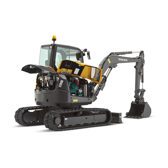
- Page 1 ECR50D English Ref. no. PUB20036502-A 2014.05 Volvo, Konz...
-
Page 2: Foreword
Service and maintenance Specifications Alphabetical index Ref. No. 20036502-A The original language is English. Original instructions. 2014.05 Copyright © 2014, Volvo Construction Equipment. All rights reserved. - Page 3 Foreword Safety regulations The machine operator is responsible for being aware of and complying with the relevant, legally prescribed, national and regional safety instructions. The safety instructions in this operator's manual are applicable only in cases where no legislated safety instructions are in force. DANGER The safety symbol combined with this signal word indicates a will result in death...
-
Page 4: Identification Numbers
Enter the identification number of machine and machine parts. This number must be specified when contacting the manufacturer to order spare parts. Positions and 20 . explanation of the PIN plates, see page Manufacturer: Volvo Construction Equipment sas rue Pierre Pingon BP 01303 Belley Cedex France PIN (Product Identification Number) of... -
Page 6: Table Of Contents
Table of contents Table of contents Foreword ..........1 Identification numbers ........3 Presentation ........... 9 Machine view ..........15 CE-marking, EMC-directive ......16 Communication equipment, installation ..19 Product plates ..........20 Information and warning decals ....22 Instrument panels ......... 26 Instrument panel, left ........ - Page 7 Table of contents Operating techniques ......87 Eco driving ............ 88 Whole-body vibrations ........89 Rules for digging ........... 91 Working within dangerous areas ....92 Attachments ..........100 Attachments, connecting and disconnecting ..........102 Attachment brackets ........103 Pressure release ......... 106 Buckets ............
- Page 8 Table of contents Specifications ........179 Recommended lubricants ......179 Fuel system ..........184 Service capacities and change intervals ..186 Engine ............187 Electrical system ......... 188 Cab ............. 190 Hydraulic system ........193 Specifications ..........194 Machine weights ......... 195 Ground pressure .........
-
Page 10: Presentation
Presentation Presentation V1140060 Intended use This machine is intended to be used under normal conditions, at an ambient temperature between -20 °C (-4 °F) and +40 °C (104 °F) and for the applications described in the Operator's Manual. The engine can be started at a maximum of -15 °C (5 °F) in cold conditions. - Page 11 Never carry out any unauthorised alterations to the cab without first, through a dealer, having discussed the alteration with personnel at the Volvo Construction Equipment Engineering Department. This department will decide whether the alteration may cause the TOPS-, ROPS- and OPG-approval to become void.
- Page 12 No modifications of any kind may be performed on this product unless each specific modification first has been approved in writing by Volvo Construction Equipment. Volvo Construction Equipment reserves the right to reject all warranty claims that have arisen due to or can be traced to unauthorized modifications.
- Page 13 Presentation available). The tracks are each driven by a two speed travel motor. Slewing system The slewing ring is driven by a hydraulic motor, which is protected against excess pressure by high pressure relief valves.
- Page 14 Presentation Anti-theft device An anti-theft device makes it more difficult to steal the machine. Volvo offers an anti-theft device as optional equipment. If your machine is not yet equipped with it, check the possibility of having such a device activated by your dealer.
- Page 15 Presentation Tool kit (optional equipment) The toolbox is located on the right side of the machine in front of the cooling package. Open the engine hood to access it. The machine comes with a number of tools, see below. V1139939 1 Tool box V1139940 Tools in the toolbox...
-
Page 16: Machine View
Presentation Machine view Machine view V1140063 Bucket 10 Additional counterweight (optional) Bucket cylinder 11 Undercarriage Dipper arm 12 Travel motor Dipper arm cylinder 13 Tracks Boom 14 Superstructure Boom cylinder 15 Boom offset cylinder Working lights 16 Dozer blade Rear hood 17 Dozer blade cylinder Engine hood 18 Battery disconnect switch... -
Page 17: Ce-Marking, Emc-Directive
The sound certificate includes both measured external values and guaranteed sound power level. These declarations are issued by Volvo for every individual machine. This EU-declaration also includes attachments manufactured by Volvo. The documentation is a valuable document and shall be saved in a safe location for at least ten years. - Page 18 Presentation CE-marking, EMC-directive If other electronic equipment is fitted to this machine, the equipment must be CE marked and tested on the machine with regard to electromagnetic interference.
- Page 19 EU conformity certificate We, the manufacturer Volvo Construction Equipment sas Rue Pierre Pingon BP 01303 Belley Cedex France The technical documentation is maintained by: Mr. Marc Gergaud, Volvo Construction Equipment, Belley France declare that the following equipment Excavator Model Serial Output...
-
Page 20: Communication Equipment, Installation
NOTICE All installation of optional electronic communication equipment must be performed by trained professionals and in accordance with the Volvo Construction Equipment instructions. Protection against electromagnetic interference This machine has been tested according to EU's directive 2004/108/EC that regulates electromagnetic interference. -
Page 21: Product Plates
Presentation Product plates Product plates The following illustrations and descriptions show the product plates on the short swing radius excavator. When ordering spare parts or for short enquiries by phone and in correspondence you should always specify model designations and product identification number. - Page 22 Presentation Product plates 2 Engine identification plate The engine identification contains information about manufacturer, designation and engine serial number. 3 TOPS/ROPS and OPG plate The plate is located inside the cab above the rear windscreen. TOPS (Tip-Over-Protection-Structure) and ROPS (Roll-Over-Protection-Structure) provide roll over protection in case the machine should turn over.
-
Page 23: Information And Warning Decals
Presentation Information and warning decals Information and warning decals The operator should know and pay attention to the information and warning plates/decals which are positioned on the machine. All plates/decals are not installed on all machines, as they are market and machine dependent. - Page 24 Presentation Information and warning decals 2 Lifting points. (2 lifting points undercarriage / 1 lifting point on boom) V1142066 1 WARNING Do not stand in the vicinity of a raised load. (decal on both sides of the boom) 4 WARNING! Track tension, check the 3 Tie down points.
- Page 25 Presentation Information and warning decals 10 Locking console 9 Sound power level outside the machine. 12 WARNING Rotating parts and hot surfaces. 11 Alternative exit path. 14 Fuel filler point. 13 WARNING Do not enter the machine’s working area. Risk for crushing! (LH) (RH) (RH)
- Page 26 Presentation Information and warning decals 17 Hydraulic oil filler point. 18 Lubrication and maintenance chart. V1065366 19 Volvo Coolant VCS (For coolant 156 ) specifications see page V1065344 20 WARNING Hot coolant under pressure.
-
Page 27: Instrument Panels
Instrument panels Instrument panels NOTE! Do not operate the machine until you know the function and position of the instruments and operating controls. Carefully read through this Operator’s Manual, your safety is involved! Keep the manual in the cab so that it is always at hand when needed. -
Page 28: Instrument Panel, Left
Instrument panels Instrument panel, left Instrument panel, left 1. Attachment bracket unlocking switch (optional equipment) Switch to unlock the attachment bracket with safety function. The switch is working differently depending on whether you have single acting or double acting system. The buzzer will sound as long as the attachment bracket is unlocked. -
Page 29: Display Unit
Central warning lamp Display panel Fuel level gauge Engine coolant temperature gauge Seat belt not fastened Offset boom activated Dozer blade floating — not applicable for ECR50D 5,6,7,8 Overload warning function activated 9,10, Engine oil pressure low 11,12 Attachment bracket open Regeneration symbols —... - Page 30 This lamp lights up if the offset boom is activated. V1077661 7 Dozer blade floating (green) — not applicable for ECR50D This lamp is not applicable for the ECR50D, it appears at every machine start and disappears again after 2 seconds. V1128175...
- Page 31 11 & 12 Regeneration symbols (yellow) — not applicable for ECR50D These two lamps are not applicable for the ECR50D, they appear at every machine start and disappear again after 2 seconds. V1138627 13 Power socket...
- Page 32 Instrument panels Display unit 14 Operating hour meter (optional equipment) The operating hour meter shows the total number of hours with the engine running. It is located inside the cabin on the lower part of the right console. 1/10 V1138629 Display panel 43 ) to Use the buttons on the keypad (see page...
- Page 33 Instrument panels Display unit Machine hour and daily hour The machine hour and daily hour screen appears 00172.5 h when pressing arrow-down from the main screen. 5.7 h This screen shows the complete machine working hours and the daily working hours. The daily working hours value can be reset.
- Page 34 Instrument panels Display unit Press the SELECT button to save the setting or press ESC to escape without saving. NOTE! The setting screen for the boom offset swing speed appears also when pressing the boom offset selection button on the right control lever. Hydraulic max.
- Page 35 Instrument panels Display unit Hydraulic max. flow for X3 (optional equipment) The hydraulic maximum flow for X3 screen appears when pressing arrow-down five times from the main screen. V1138811 The setting mode screen for hydraulic maximum flow for X3 appears when pressing the SELECT button from the X3 screen.
- Page 36 Instrument panels Display unit Auto idle time The auto idle time screen appears when pressing arrow-down six times from the main screen. 20 s The basic concept of the auto idle system is to reduce the fuel consumption. The engine speed will be lowered automatically to idle mode if auto idle is 20 s activated and no control levers or pedals nor the...
- Page 37 Instrument panels Display unit Press the SELECT button to save the setting or press ESC to escape without saving. NOTE! An information in the display comes up 1 minute before the shut down to inform that the automatic shut down sequence is started. Additionally the buzzer sounds 3 seconds before the end of the shut down sequence.
- Page 38 The engine rpm can not be changed anymore. V1139787 Put the machine in a safe place, turn it off and contact your authorized Volvo Construction Equipment workshop. Boom swing max. flow setting This symbol is shown when the boom swing maximum flow is adjusted with the joystick, see 48 for further information.
- Page 39 During this additional 1 minute the machine can be moved out of a possible dangerous area. Investigate the cause and contact your authorized Volvo Construction Equipment workshop if necessary. Engine high coolant temperature countdown 00:15 This symbol is shown if the engine coolant temperature is too high.
- Page 40 This symbol is shown if the engine coolant temperature is too high. Turn off the engine, investigate the cause and V1139796 contact your authorized Volvo Construction Equipment workshop if necessary. Engine oil pressure low This symbol is shown if the engine oil pressure is too low.
- Page 41 This symbol is shown if there is a failure in preheating. Turn off the engine, investigate the cause and V1139801 contact your authorized Volvo Construction Equipment workshop if necessary. Automatic engine shut down effective 00:00 This symbol is shown when the automatic engine shut down function has shut down the engine (end of the countdown).
- Page 42 Recovery code screen If the wrong code is entered more than 3 times, a recovery code consisting of 5 digits appears. Note down this code and contact your Volvo Construction 1 0 8 6 0 Equipment dealer. V1138794 Anti-theft system: code change The anti-theft screen appears when pressing arrow- down nine times from the main screen.
- Page 43 Instrument panels Display unit Change third code Press SELECT when the main screen is shown. Select the third code and press SELECT to change this code. Enter the old third code and press SELECT. _ _ _ _ Enter the new code and press SELECT. _ _ _ _ Repeat the new code and confirm with SELECT.
-
Page 44: Instrument Panel, Right
Instrument panels Instrument panel, right Instrument panel, right Ignition switch Keypad Switch for rotating warning beacon (optional equipment) Switch for fan Switch for windscreen wiper and washer Temperature control (for air conditioning) V1138171 1. Ignition switch The ignition switch is used for preheating and STOP starting. - Page 45 Instrument panels Instrument panel, right Menu up Escape Menu down Select ECO mode RPM up not assigned RPM user setup 1 RPM down RPM user setup 2 not assigned 1 Fast travel speed After switching to fast travel speed the automatic control of the travelling speed is activated.
- Page 46 Instrument panels Instrument panel, right 4 Working lamps: front and boom / rear (boom and rear working lights: optional equipment) Press this button once to switch on the front working lights. Press it a second time to switch on the boom and rear working lights (optional equipment).
- Page 47 15 RPM up Press this button to increase the engine RPM. 16 not assigned This key is not assigned on the ECR50D. 17 RPM user setup 1 Press the RPM user setup 1 button to set the engine RPM to the value stored under this button.
- Page 48 Instrument panels Instrument panel, right 3. Switch for rotating warning beacon (optional equipment) Two position switch Press upper end of switch = The rotating warning beacon is on and the green indicator lamp on the lower end of the switch is alight. V1085618 Press lower end of switch = The rotating warning beacon is off.
-
Page 49: Other Controls
Other controls Controls Other controls Controls V1138043 V1138111 V1138044 Left hand control lever for working equipment Horn Proportional roller for rotating attachments Control lockout lever for hydraulics Control levers for travel motion Right hand control lever for working equipment Selector switch; offset boom or attachment movement Switch for optional equipment, such as hammer... - Page 50 Other controls Controls 1. Left control lever for working equipment (ISO control pattern) WARNING (LH) Risk of serious accidents. Unfamiliar control patterns could cause confusion and accidents resulting in serious injury. Use extreme caution when using the control levers V1087059 after changing the control pattern and until you become familiar with the new pattern.
- Page 51 Other controls Controls 3. Proportional roller for rotating attachments The proportional roller operates the optional equipment (X3, for example rototilt bucket). 4. Control lockout lever for hydraulics WARNING Risk of crushing. A raised attachment could fall and cause crushing injury. Before leaving the cab, always lower all attachments to the ground and lock the control functions.
- Page 52 Other controls Controls 6. Right control lever for working equipment (ISO control pattern) WARNING (RH) Risk of serious accidents. Unfamiliar control patterns could cause confusion and accidents resulting in serious injury. Use extreme caution when using the control levers V1087067 after changing the control pattern and until you become familiar with the new pattern.
- Page 53 Other controls Controls changes between offset boom and attachment movement. The switching mode can operate only if the roller is in neutral position. NOTE! V1089765 The control lamp in the front instrument panel lights Control lamp: offset boom up when operation with the offset boom is activated. 8.
- Page 54 Other controls Controls sound appears two times when the settings menu is activated. The display shows the X1 menu settings and during this time the selector switch for offset boom or optional equipment (8) is only for validation but not full flow accessory activation. 3 To change the setting for the X1: Move the proportional roller (9) on the right control lever to the left or right until the wanted maximum...
- Page 55 Other controls Controls 10. Dozer blade control lever The control lever controls the position of the dozer blade and activates the float blade. Lever forward: Dozer blade down. Lever backward: Dozer blade up. V1089831 Lift the upper part of the lever and push forward to activate the float blade.
-
Page 56: Rops
Other controls ROPS ROPS ROPS Cab (Roll Over Protective Structure) The cab is designed to ensure minimum crash protection space according to the standard currently being developed by the International Standard Organization. NOTE! Do not jump out of cab if the machine should roll over. - Page 57 V1087090 hammer (hydraulic breaker) protection kit is also A OPG Top B OPG Front available. Consult your local Volvo Construction Equipment dealer for information about when the different options can be used. NOTICE Always, check clearance between bucket and Cab/ OPG guard.
-
Page 58: Operator Comfort
Other controls Operator comfort Operator comfort Operator's seat, adjusting A correctly adjusted operator’s seat is an essential contribution to operator comfort and safety! WARNING Risk of serious accidents. Sudden movement of operator's seat could cause loss of machine control. This could result in accidents with serious injuries. - Page 59 Every 3 years the seat belt must be changed regardless of its condition. The seat belt must be replaced by your Volvo dealer. Modifications to the belt or its mountings are not permitted.
- Page 60 Other controls Operator comfort Windows Upper windscreen The windscreen (9) can be loosened by pushing the buttons (10) on both sides and then slide the windscreen upwards under the cab roof. NOTICE The windscreen is fastened in the roof when you hear a click.
- Page 61 The recommendations below are based on standard working, install the necessary additional protection guards in accordance with work site conditions and local government recommendations. Consult your local Volvo Dealer.
- Page 62 (1) on the backside of the operator seat. V1140430 Fire extinguisher, location Possible location for a fire extinguisher is behind the seat with a special fixation bracket offered by Volvo Construction Equipment. Contact your dealer for further information about this fire extinguisher fixation bracket. Emergency exit The alternative exit path is the sliding window on the right side (it’s location marked with an information...
- Page 63 Other controls Operator comfort Audio system (optional equipment) The audio system (optional equipment) is located below the cab roof on the right hand side of the machine. Check which of the two radio versions is built in your machine. Radio with CD Mute / Power 10 Preset 5 Sound styles...
- Page 64 Other controls Operator comfort Radio with USB, SD and Bluetooth 1 2 3 V1143312 SCR button Preset 1–5 ON/OFF button MENU button Volume control 10 Green phone button Display 11 Red phone button SEARCH/ 12 SD card slot CHANGE/SELECT button USB socket 13 DISP button Front AUX-IN...
- Page 65 Other controls Operator comfort Other operating modes: Select a track. 6 USB socket 7 Front AUX-IN socket 8 Preset 1–5 Short press: Call up the stored station in radio mode. Long press: Store station in the current memory bank in radio mode. 9 MENU button Short press: Open and close the menu.
-
Page 66: Climate Control System
Other controls Climate control system Climate control system Climate control system The temperature control and the fan are only operable when the engine is running. The air condition is switched on and off with a button on the keypad and the temperature is adjusted by a regulator on the right instrument panel. -
Page 67: Operating Instructions
Operating instructions Operating instructions This chapter contains rules which must be followed in order to operate the machine safely. However, these rules are to be followed in conjunction with laws or other national regulations applicable to road safety and labour welfare. Alertness, judgement and respect for applicable safety regulations are conditions for avoiding risk of accidents. - Page 68 Operating instructions Standard ISO 5006 "Earthmoving machinery – Operator’s field of view" is dealing with the operator’s visibility around the machine and is meant to be used for measuring and evaluate the visibility. Compliance with this standard gives improved visibility around the machine. The machine is tested according to methods and criteria for this standard.
-
Page 69: Safety Rules When Operating
Operating instructions Safety rules when operating Safety rules when operating Follow the safety rules in the Operator's Manual before performing any operation. Operator obligations WARNING Risk of fatal accidents. Unauthorised persons within the work area around the machine could lead to serious crushing injury. •... - Page 70 Operating instructions Safety rules when operating The operator must be in control of the working area of the machine. - Prevent persons from walking or standing under raised excavating equipment, unless it has been made safe or supported. - Prevent persons from entering or remaining in the danger area, that is a distance of at least 7 m (23 ft) in all directions from operating machines.
- Page 71 Operating instructions Safety rules when operating Operator safety WARNING Risk of fatal accidents. Unauthorised persons within the work area around the machine could lead to serious crushing injury. • Clear all unauthorised personnel from the working area. • Keep a lookout in all directions. •...
- Page 72 Operating instructions Safety rules when operating (Operator Protective Structure) and TOPS (Tip- 10 . Over Protective Structure), see page During electrical storms, do not enter or exit the machine. - If you are off the machine, stay well away from the machine until the electrical storm passes.
- Page 73 Operating instructions Safety rules when operating Periodic replacement of critical parts for safety To ensure safety at all times when operating or driving the machine, periodic maintenance must always be carried out. To further improve safety, it is also recommended that periodic check or replacement of the parts given in the table below, is carried out.
-
Page 74: Measures Before Operating
Operating instructions Measures before operating Measures before operating For safety, observe the following rules. - Read the Operator's manual. 174 . In cold - Carry out daily service, see page weather, make sure that the freezing point of the coolant is sufficiently low and that the lubricating oil is intended for winter use. -
Page 75: Starting Engine
Operating instructions Starting engine Starting engine Starting engine 1 Turn on the electric supply with the battery disconnect switch. V1090371 The battery disconnect switch is located in the front of the machine. 2 Shift control lockout lever (4) to position (A). You are now able to start the engine and the operating levers for working and travel hydraulics are locked (no movement possible). - Page 76 Operating instructions Starting engine 10 Shift control lockout lever (4) to horizontal position to be able to operate the machine. Avoid excessive loading of the engine immediately after starting. Observe the warm-up instructions. NOTE! Never operate the machine without having the seat belt fastened, your safety is involved! Warming up NOTICE...
-
Page 77: Stopping
Operating instructions Stopping Stopping WARNING STOP Risk of crushing. A raised attachment could fall and cause crushing injury. Before leaving the cab, always lower all V1087043 Ignition key attachments to the ground and lock the control P: Radio and cab interior light functions. -
Page 78: Parking
Operating instructions Parking Parking WARNING Risk of crushing. A raised attachment could fall and cause crushing injury. Before leaving the cab, always lower all attachments to the ground and lock the control V1142419 functions. Parking position 1 Park the machine on firm, horizontal ground. 2 Park the machine in the parking position as shown on the picture: open the bucket and lower it to the ground and lower the dozer blade to the... - Page 79 Operating instructions Parking By etching in the PIN-number or the national licence plate number of the machine on its windows, it is easier to identify stolen machines. Long-term parking If the machine is not going to be used for a longer period, all cylinder rods must be protected against corrosion.
-
Page 80: Retrieving And Towing
Operating instructions Retrieving and towing Retrieving and towing WARNING Risk of runaway machine. Improper towing methods or faulty equipment could cause the machine to break away from the towing vehicle, causing accidents, serious injury or death. Carefully follow the towing instructions and use only certified towing equipment with adequate load rating. - Page 81 Operating instructions Retrieving and towing of the machine. Be careful there should not be also interference with parts of the machine. NOTE! Keep the cable horizontal, straight, and parallel to the tracks.
-
Page 82: Attachments, Alternative Lowering
Operating instructions Attachments, alternative lowering Attachments, alternative lowering WARNING Risk of crushing. Incorrect function of the line rupture valves may cause uncontrolled lowering of the attachment. Do not enter under the attachment when working with the alternative lowering function. Even in technical incidents the attachment can be lowered to the ground. - Page 83 Operating instructions Attachments, alternative lowering Lowering attachment in case of problems with the electric circuit In case of standstill or engine defect and power failure. 1 Open the rear hood. 2 Loosen screw (C) (end of the pin) on the left solenoid valve.
-
Page 84: Transporting Machine
Operating instructions Transporting machine Transporting machine When transporting the machine pay attention to applicable regulations regarding weight, width, height, length and securing the load. Make sure that the ramp is of ample width, stability, thickness and length. Remove sludge, grease, oil etc. from ramp and trailer in order to avoid slipping of the machine Block both crawler tracks after loading and lash the machine down with chains and belts of sufficient... - Page 85 For 195 . machine weight, see page NOTE! Volvo is not responsible neither for lifting equipment nor for lifting techniques. 8 The distance (C) between axis (A) and (B) at the lifting point on the boom and distance (D) must be observed when lifting.
- Page 86 Operating instructions Transporting machine Loading Loading machine on trailer WARNING Risk of fatal accidents. Unexpected driving direction could lead to accidents resulting in serious injury or death. Always check the driving direction before moving the machine. NOTE! Make sure that loading ramps and platforms are free from oil, mud, ice and similar so that the machine does not begin to slip.
- Page 87 Operating instructions Transporting machine 8 Switch off the battery disconnect switch. 9 Lock the cab door and all lockable covers. 10 Secure both tracks with wheel chocks (2) and tie the machine with chains and belts (3) with the cross tie down procedure to the loading platform of the trailer.
-
Page 88: Operating Techniques
Operating techniques Operating techniques The excavator is a multi-task machine capable of being fitted with multitude special attachments to perform many types of work. This chapter contains information and instructions regarding the best operating practices to improve efficiency, including examples on how the most common attachments are used. -
Page 89: Eco Driving
The right equipped machine saves on fuel and maintenance. See the operating techniques chapter for further information about equipment. Contact your local Volvo Construction Equipment dealer for further information and the possibility to attend a Volvo training for fuel efficient machine operating. -
Page 90: Whole-Body Vibrations
Operating techniques Whole-body vibrations Whole-body vibrations Whole-body vibration emission on construction machinery are affected by a number of factors, such as working mode, ground conditions, speed, and so To a large extent the operator can influence the actual vibration levels, because the operator controls the speed of the machine, its working mode, the travel path, and so on. - Page 91 Operating techniques Whole-body vibrations - Transport machines when there are long distances between worksites. Back pain associated with whole-body vibrations may be caused by other risk factors. The following guidelines can be effective to minimize risks of back pains: - Adjust the seat and controls to achieve good posture.
-
Page 92: Rules For Digging
Operating techniques Rules for digging Rules for digging WARNING Risk of serious injury. More than one person in the cab while operating could cause accidents and serious injury. Only the operator, seated in the operator’s seat, may be in the cab when operating. All other persons must keep at a safe distance from the machine. -
Page 93: Working Within Dangerous Areas
Operating techniques Working within dangerous areas Working within dangerous areas Observe great care at marked danger areas. Do not operate too close to the edge of a quay, ramp, and so on. Move slowly when working in confined spaces and check that there is sufficient room for machine and load. - Page 94 Operating techniques Working within dangerous areas operator at fairly great distances from the power line. Voltage Minimum distance to power line 0 ~ 50 kV 3 m (10 ft) 50 ~ 69 kV 4.6 m (15 ft) 69 ~ 138 kV 5 m (16.4 ft) 138 ~ 250 kV 6 m (20 ft)
- Page 95 Operating techniques Working within dangerous areas - All other persons should keep away from the machine, ropes, and load. - The operator should try to remove the machine from contact by moving it in the reverse direction from that which caused the contact. - If the machine cannot be moved away from contact, the operator should remain inside cab until the lines have been de-energized.
- Page 96 Operating techniques Working within dangerous areas Working on slopes WARNING Risk of tipping over. When working on uneven slopes and ground the machine can tip over. Make sure the maximum machine inclination is not exceeded and that the inclination angle is not increased by an obstacle.
- Page 97 Operating techniques Working within dangerous areas loaded bucket. In unavoidable case, pile up earth on the slope, and then make the machine level and stable. While travelling on a slope, keep the angle between boom and arm at 90 - 110°, raise the bucket 20 - 30 cm (7.9–11.8 in) from the ground If the engine shuts down on a slope, lower the attachment to the ground.
- Page 98 Operating techniques Working within dangerous areas Working where there is risk of landslip Always check ground conditions before beginning to work. If the ground is soft, great care must be taken when positioning the machine. Thawing of frozen ground, rain, traffic, piling and blasting are factors which increase the risk of landslip.
- Page 99 Operating techniques Working within dangerous areas Working in cold weather DANGER Risk of electrical shock. Personal injury results if a body part comes into contact with a machine that conducts electric power. Disconnect the electrical engine heater before working on the machine. WARNING Risk of frostbite.
- Page 100 Operating techniques Working within dangerous areas Demolition work The machine is often used for demolition work. Be extremely careful and study the work site thoroughly. Use fall protection over the cab against falling objects. Make sure that the material, on which the machine is standing, cannot collapse or slide.
-
Page 101: Attachments
EU Machine Safety Directive is stated on the product plate of the machine by the way of a CE marking. Therefore, this marking also covers attachments which are designed and marked by Volvo Construction Equipment, as they are an... - Page 102 Operating techniques Attachments integrated part of the machine and adapted to the machine. Volvo Construction Equipment is not responsible for attachments manufactured by other companies. Such attachments must be CE marked and accompanied by a Declaration of Conformity and user instructions.
-
Page 103: Attachments, Connecting And Disconnecting
Operating techniques Attachments, connecting and disconnecting Attachments, connecting and disconnecting WARNING Risk of crushing. Falling attachments could result in severe injury or death. Make sure the attachment bracket is properly locked before starting work. WARNING Risk of crushing. An unsecured attachment could fall and cause serious injury or death. -
Page 104: Attachment Brackets
Operating techniques Attachment brackets Attachment brackets Volvo Attachment bracket NOTE! For other types of attachment brackets please refer to the separate attachment bracket Operator Manuals. WARNING 1 Front hook Risk of crushing. 2 Rotating hook Raised equipment may drop if the hydraulic system 3 Locking pin fails or if the control is operated. - Page 105 Operating techniques Attachment brackets 1 Remove the linch pin and extract the locking pin. 2 Rotate the locking pin 90° to lock it in extracted position. 3 Lower the dipper arm into a position where the attachment bracket connects with the front bucket pin.
- Page 106 Operating techniques Attachment brackets 5 Insert the release bar into the hole at the back of the attachment bracket. To release the attachment bracket, insert the release bar and pull. 6 Pull the release bar to release the attachment bracket from the rear bucket pin. WARNING Risk of crushing.
-
Page 107: Pressure Release
Operating techniques Pressure release Pressure release Pressure release Before removing or connecting hydraulic hoses the pressure in the hydraulic system must be released. WARNING Risk of high pressure injection. Residual pressure in the hydraulic system could lead to oil under high pressure jetting out and cause serious injury, even if the engine has not been running for some time. -
Page 108: Buckets
Operating techniques Buckets Buckets Working with buckets Digging a trench When excavating a trench it is recommended to dig in layers, thus to obtain a level trench bottom. Use a combination of bucket, dipper and boom motions to maintain the angle of the bucket while digging. 1 Anchor the dozer blade into the ground behind the machine. -
Page 109: Offset Boom
The minimum radius R1 of the equipment is as follows. Offset in ECR50D degree (°) to left 76° to right 56° ECR50D minimum radius, mm (in) Type Short dipper Long dipper 1400 mm 1800 mm (55.12 in) (70.87 in) to left... -
Page 110: Special Hydraulics
Volvo supplies a wide range of hydraulic tools. All tools and optional equipment are described in the Attachment Catalogue. Contact a Volvo dealer for... -
Page 111: Hammer
Operating techniques Hammer Hammer Working with hammer (hydraulic breaker) WARNING Risk of severe personal injury. While working with the hammer flying chips of rock could cause severe injury. Provide protective nets for the windscreens. Keep windows and door closed and prevent persons from entering the risk zone when operating the hammer. - Page 112 Operating techniques Hammer 4 Place the boom and hammer in the breaking position. Quick and careless boom movements could result in damage to the hammer. Position for hammer use 5 Place the tool perpendicular to the surface of the object. Keep the feed force aligned with the tool. Avoid small irregularities on the object which will break easily and cause either idle strokes or an incorrect working angle.
- Page 113 Operating techniques Hammer see page 106 for the procedure to release the hydraulic pressure. WARNING Risk of high pressure injection. Residual pressure in the hydraulic system could lead to oil under high pressure jetting out and cause serious injury, even if the engine has not been running for some time.
- Page 114 Operating techniques Hammer Disconnecting with pivot pins 1 Place the machine on firm and level ground. 2 Lower the boom and place the hammer flat on the ground. 3 Release the pressure from the hydraulic system 106 . according to the procedure on page 4 Remove the ignition key to make sure the engine cannot be started.
-
Page 115: Thumb
Thumb Thumb Thumb attachment Lubricate the thumb pivot pin every 50 hours or every 8 hours in aggressive, corrosive conditions (VOLVO Ultra Grease Moly EP2 or equivalent is recommended). Check the hydraulic lines wear status every day. Safety NOTE! Do not operate the machine until you know the function and position of the instruments and operating controls. - Page 116 Check with your Volvo Dealer that your machine is properly equipped. The thumb is only approved for use with Volvo designed or approved buckets and attachments. If the thumb is used with other buckets or attachments, it may not work properly.
- Page 117 Operating techniques Thumb 2 Connect the hydraulic hoses to connection C and D. If another attachment is used, disconnect the hydraulic lines and put the quick couplings in their support (located on each side of the dipper arm). NOTICE Protect the hydraulic connections against dirt, because only this will ensure the correct function of hydraulic connections and hydraulic system.
- Page 118 Operating techniques Thumb Working with thumb WARNING Risk of crushing. A falling load could cause serious crushing. Lifting a load with the dipper arm's welded thumb plate could cause the plate to break and the load to fall. Never use the welded thumb plate on the dipper V1078515 arm as a lifting device.
-
Page 119: Clamshell Bucket
Operating techniques Clamshell bucket Clamshell bucket Hydraulic equipment for clamshell The hydraulic equipment for the clamshell enables the connection and use of a clamshell. WARNING Risk of high pressure injection. The hydraulic oil is under high pressure. Discharging hydraulic oil will cause serious injury when injected into the skin. - Page 120 Operating techniques Clamshell bucket have done that you are able to use the connections B and E. NOTICE Protect the hydraulic connections against dirt, because only this will ensure the correct function of hydraulic connections and hydraulic system. NOTE! Depending on the equipment the hydraulic connections on the boom can vary from the illustration and the description.
- Page 121 Operating techniques Clamshell bucket Clamshell operation The clamshell is operated with proportional roller (9) on the right multi-function lever. With the proportional roller (9) the clamshell can be rotated in two directions. Control lever to the right: Empty the clamshell (opening).
-
Page 122: Hose Rupture Valves
Operating techniques Hose rupture valves Hose rupture valves (optional equipment) WARNING Risk of crushing by falling attachments. Hydraulic or mechanical failure could cause the attachments to fall, resulting in severe personal injury or death. Ensure no persons can enter the danger zone until the failure is resolved. -
Page 123: Tracks
Operating techniques Tracks Tracks When using rubber tracks WARNING Risk of crushing. Moving tracks could cause serious crushing injury. Always ensure that no persons are near the tracks while the machine is in motion. Moving over obstacles When reversing over an obstacle, a gap is formed between the rollers (1) and track (2). - Page 124 Operating techniques Tracks Misaligned tracks The track may come off in the following conditions: When the idler or track rollers are no longer aligned with the core because the track has moved out of alignment. If the machine is reversed in this condition, the track will come off.
-
Page 125: Lifting Objects
For more detailed information you should contact your authorized Volvo dealer. V1087143 Only lift objects using the approved lifting point on the machine (A). Contact your Volvo dealer if any doubt. V1087144 WARNING The blade must be in upper position during lifting operation if no hydraulic Risk of crushing. - Page 126 Operating techniques Lifting objects - Specific machine knowledge and training how to properly rig the load. - Full responsibility for all aspects of the lift. Interrupt the lift if not fully confident of a safe lift. Select machine with sufficient capacity for the total expected load, reach and swing.
- Page 127 Operating techniques Lifting objects Stability The stability of working machines is highly changeable and exposed to great variations In order to carry out the work safely, the operator must himself or herself think about and take into consideration the particular conditions that apply at a specific moment.
- Page 128 Operating techniques Lifting objects Lifting capacities Lifting capacities are 75% of the tipping load or 87% of the hydraulic limit. NOTE! If the overload warning lamp lights up, you have reached the maximum lifting limit. Immediately lower the equipment and unload some of the weight or move to a more safe position where the light does not illuminate.
-
Page 129: Signalling Diagram
Operating techniques Signalling diagram Signalling diagram Manual signalling to an operator of a mobile excavator as per SAE J1307. The primary use of hand signals is for a signalman to direct the lifting, handling, and placement of loads attached to working equipment. Hand signal usage may also be applicable to earth moving operations and/or machine travel when the operator's visibility is obstructed. - Page 130 Operating techniques Signalling diagram SLEW DIPPER ARM INWARD With either arm extended horizontally, point with forefinger With both hands clenched, to direction of slew rotation. point thumbs inward. V1065930 V1104050 V1104049 DIPPER ARM OUTWARD RETRACT TELESCOPIC EXTEND TELESCOPIC With both hands clenched, BOOM BOOM point thumbs outward.
- Page 131 Operating techniques Signalling diagram TRAVEL THIS FAR TO GO Raise forearm with closed fist indicating inside of turn. With hands raised and open Move other fist in vertical circle indicating direction of track inward, move hands or wheel rotation. laterally, indicating distance to go.
-
Page 132: Safety When Servicing
Safety when servicing Safety when servicing This section deals with the safety rules which should be followed when checking and servicing the machine. It also describes the risks when working with unhealthy material and ways to avoid personal injuries. Further safety rules and warnings texts are given within the respective sections. -
Page 133: Service Position
The stability of the machine is a prerequisite for safe assembly, maintenance and repair work. When replacing spare parts make sure to use genuine Volvo spare parts. Do not use any spare parts of lower quality. Cleanliness is decisive for the operating safety of the complete machine. -
Page 134: Before Service, Read
Lifting devices, tools, working methods, lubricants and parts prescribed in the Operator's Manual should be used. Volvo Construction Equipment will not accept any responsibility otherwise. Make sure that no tools or other objects, which may cause damage, have been forgotten in or on the machine. - Page 135 Safety when servicing Before service, read Release the pressure in the hydraulic system before starting the service work.
- Page 136 Safety when servicing Before service, read Never set a relief valve to a higher pressure than that recommended by the manufacturer. Machines, which are used within a polluted or in another way insanitary area should be equipped for this kind of work. Special safety regulations apply when servicing such a machine.
-
Page 137: Entering, Leaving And Climbing The Machine
Safety when servicing Entering, leaving and climbing the machine Entering, leaving and climbing the machine Access to cab The cab door is fitted with an external door handle with a lock (1) and an internal door handle. The door can be locked in open position by application of manual force (a fixed locking bolt (3) on the cab engages in the round bolt receptacle (2) in the door). -
Page 138: Fire Prevention
Safety when servicing Fire prevention Fire prevention Using the machine in environments with high risk of fire or explosion requires special training and equipment. There is always a risk of fire. Find out what kind of fire extinguisher is used on your working site and how to use it. - Page 139 Safety when servicing Fire prevention and oil. Besides reducing the risk of fire, it is also easier to detect faulty or loose components. NOTE! Take great care if a high-pressure wash is used for cleaning. Electrical components and electrical leads can be damaged even at a moderately high pressure and temperature.
- Page 140 Safety when servicing Fire prevention Check that fuel lines, hydraulic and brake hoses and electrical cables have not been damaged by chafing or are not in danger of being damaged in that way because of incorrect installation or clamping. This applies particularly to unfused cables, which are red and marked R (B+) and routed: - between the batteries...
-
Page 141: Handling Hazardous Materials
Safety when servicing Handling hazardous materials Handling hazardous materials Heated paint WARNING Risk of toxin inhalation. Burning of painted, plastic or rubber parts produces gases that could damage respiratory tracts. Never burn painted or rubber parts or any plastics. Heated paint gives off poisonous gases. Therefore, paint must be removed from an area with a radius of at least 10 cm (4 in) before carrying out welding, grinding or gas cutting. - Page 142 Safety when servicing Handling hazardous materials Heated fluoro-carbon rubber WARNING Risk of serious injury. At very high temperatures fluoro-carbon rubber forms substances which are very corrosive to skin and lungs. Always wear personal protective equipment. When handling a machine which has been damaged by fire or been exposed to intense heat, the following measures should be taken: Use thick, rubber gloves and wear protective...
- Page 143 Safety when servicing Handling hazardous materials Batteries WARNING Risk of chemical burns. The battery electrolyte contains corrosive sulphuric acid which could cause severe chemical burns. If electrolyte spilled on your bare skin, remove it immediately and wash the affected area with soap and plenty of water.
-
Page 144: Handling Line, Tubes And Hoses
If oil or fuel leaks from high pressure hoses or loose screws is found, stop operations immediately and contact an authorized Volvo dealer workshop. Do not bend high pressure lines. Do not strike high pressure lines. Do not install any lines that are bent or damaged. -
Page 145: Service And Maintenance
174 . will be indicated. See page Service history After each completed service at a workshop authorised by Volvo Construction Equipment, the 206 . service history should be filled in, see page Service history is a valuable document, which can be referred to when for example selling the machine. - Page 146 Volvo. The service program is continuous with fixed intervals. The operating time between intervals only applies if the machine is used in normal environment and operating conditions. Ask your Volvo dealer what is right for your specific machine.
- Page 147 Service and maintenance Cleaning machine The machine should be cleaned regularly with conventional car care products in order to eliminate the risk of damage to the paint finish and other surfaces on the machine. NOTICE Avoid using strong cleaning agents or chemicals in order to minimise the risk of damage to the paint finish.
- Page 148 Service and maintenance - Finish by rinsing the whole machine with only water. - Always lubricate the machine after washing. - Touch-up the paint finish when required. Paint finish maintenance Machines which are used in corrosive environment suffer more from rust than others. As a preventive measure it is recommended that the paint finish should be maintained every sixth months.
- Page 149 Service and maintenance When operating in other environments, inspection and cleaning is required at least once a week. Loose material is removed with for example compressed air. Cleaning should preferably be carried out at the end of the working shift before the machine is parked. Use personal protective equipment such as protective goggles, gloves and respirator.
-
Page 150: Service Points
Service and maintenance Service points Service points Service points V1137642 Battery disconnect switch Battery Hydraulic tank breather Hydraulic oil tank Hydraulic oil filter Hydraulic oil level sight glass, filling and drain filter Fuel filler neck Fuel filter Air filter Water separator Expansion tank Radiator Hydraulic oil cooler... - Page 151 Service and maintenance Service points Engine oil dipstick Engine oil filler neck...
-
Page 152: Engine
Service and maintenance Engine Engine Engine oil level, checking Check the engine oil level every 10 hours. NOTE! Check the engine oil level when the engine is cold. 1 Park the machine on level ground and place it in 132 . service position, see page 2 Turn the battery disconnect switch off. -
Page 153: Fuel System
For fuel quality, see page 184 . Fuel tank Any repair or modification of the fuel tank must be done by persons authorized by Volvo, contact your Volvo Construction Equipment dealer. Fuel level, checking WARNING Risk of explosion! Flammable liquids could explode. - Page 154 Service and maintenance Fuel system Water separator, draining WARNING Risk of explosion! Flammable liquids could explode. Smoking, open flame and fire are prohibited. 1 Park the machine on level ground and place it in 132 . service position, see page 2 Turn the battery disconnect switch off.
-
Page 155: Engine Air Cleaner
Contact V1085800 your Volvo Construction Equipment dealer. Check the air lines (filter - engine) for leaks during every maintenance. Defective parts must be replaced and loose hose clamps must be tightened. - Page 156 Secondary air filter, replacing (optional equipment) The secondary filter must be replaced when the primary air filter was replaced three times or every second year. Contact your Volvo Construction Equipment dealer. NOTE! The secondary filter must not be cleaned. The engine must not be operated just with the secondary filter installed.
-
Page 157: Cooling System
To avoid damage to the engine, it is very important that Volvo Coolant VCS is used when V1066019 filling or changing the coolant. Volvo Coolant VCS is yellow and a decal by the filling point shows that the system is filled with this coolant (see picture). NOTICE... - Page 158 Service and maintenance Cooling system NOTICE In order to avoid damage to engine and cooling system, different brands of coolant or corrosion protection must not be mixed. Freeze protection Content of concentrated down to coolant -25 °C (-13 °F) -35 °C (-31 °F) -46 °C (-51 °F) Coolant level, checking Check the coolant level every 10 hours.
- Page 159 (3) (optional equipment) for damage and dirt accumulations. Damaged parts in the cooling package must be replaced immediately, contact your Volvo Construction equipment dealer. 5 Clean the cooler fins with compressed air by blowing the dirt outwards from the side.
- Page 160 Service and maintenance Cooling system Coolant, topping up WARNING Risk of scalding and severe burns to unprotected skin. High pressurized hot coolant may rush out of expansion tank and cause severe burns. Before removing the expansion tank pressure cap: Shut down the engine. Allow the engine to cool Turn the pressure cap slowly to release any pressure.
-
Page 161: Electrical System
Service and maintenance Electrical system Electrical system Check the function of all electrical components such as lights, instruments, warning lamps, wiper, washer, horn, travel alarm, heater and other optional equipment daily. In case of a blown fuse it must be replaced with a 188 . - Page 162 Service and maintenance Electrical system Starting with booster batteries, see page Starting with booster batteries . Battery WARNING Risk of fire and explosion. Battery gas contains hydrogen and is flammable and could explode. Do not open a battery close to sources of fire such as open flames, cigarettes or sparks.
- Page 163 Service and maintenance Electrical system Battery disconnect switch The battery disconnect switch must always be switched off for longer resting periods and for all repair and maintenance work on the machine. V1090371 The battery disconnect switch is located in the front of the machine. Battery, charging WARNING Risk of serious injury.
- Page 164 NOTE! Welding on the machine is not allowed. If welding on the machine is needed it has to be approved by Volvo Construction Equipment. Otherwise all additional welding is under customer responsibilities. Any unauthorized welding could lead to a loss of warranty.
-
Page 165: Travel Gearbox
Service and maintenance Travel gearbox Travel gearbox Travel gearbox oil level, checking Check the travel gear oil level every 250 hours. 1 Park the machine on horizontal ground and 132 . place it in service position, see page 2 Turn the battery disconnect switch off and make sure the machine cannot be started during maintenance step. -
Page 166: Track Unit
Service and maintenance Track unit Track unit Track unit, checking tension Check and adjust the track tension every 250 hours NOTE! Incorrect tension reduces the lifetime of the tracks. A too low track tension increases the risk of detracking. V1087191 Machine position for track tension check 1 Park the machine on horizontal ground. - Page 167 Service and maintenance Track unit NOTICE Risk of environmental pollution! The grease in the track adjustment cylinder is under high pressure and large quantities of grease will be quickly released if the valve is loosened too much. Never loosen the valve by more than two turns when draining the grease.
-
Page 168: Cab
Service and maintenance Washer reservoir The washer reservoir is located in the back of the cab on the right side cab post. 1 Open the cap (1) of the washer reservoir filling device. 2 Fill up the washer reservoir with washing fluid. 3 Close the cap (1) of the washer reservoir filling device. -
Page 169: Air Conditioning
Service and maintenance Air conditioning Air conditioning The air conditioning (optional equipment) should be checked and the cabin filter should be changed every 1000 hours. This work must only be done by authorised personnel in the dealer workshop 140 . Safety when handling refrigerant, see page... -
Page 170: Bucket Teeth
Service and maintenance Bucket teeth Bucket teeth Bucket teeth, replacing WARNING Risk of splinter injury. When striking metal objects with a hammer, flying metal chips could cause serious splinter injury to V1066078 eyes and other body parts. Special tool Always wear personal protective equipment and eye protection when replacing bucket teeth. - Page 171 Service and maintenance Bucket teeth 6 Knock down the locking device further with a hammer and the tool or other suitable drift until the upper part is just below the scored line in the hole. NOTE! Replace the steel pin in connection with replacement of tooth adapter.
-
Page 172: Hydraulic System
Service and maintenance Hydraulic system Hydraulic system Hydraulic oil level, checking Check the hydraulic oil level every 10 hours. When you check the oil, the temperature of the oil 70°C must be between 20 °C (68 °F) and 50°C (122 °F) (158F) [±5 °C (9 °F)]. -
Page 173: Greasing
Service and maintenance Greasing Greasing Bearings, greasing The service life of bushings and pivot pins can be extended considerably, if the machine is greased regularly and in the correct way. Before greasing, place the machine on horizontal ground and extend the equipment in the front, so that all cylinder grease points are accessible. -
Page 174: Lubrication And Service Chart
Service and maintenance Lubrication and service chart Lubrication and service chart Symbol key The following standard symbols are used in the lubrication and service chart. Lubrication Check travel gear oil Fuel system Check track tension Drain condensation water Check the hydraulic oil level Replace fuel filter Change the hydraulic oil Check coolant level... - Page 175 Service and maintenance Lubrication and service chart Every: 10, 50, 250, 500, 1000, 1500, 2000 and 3000 operating hours (according to Service Programme of the machine). 6000 h 1000 h 500 h 250 h 50 h 10 h 10 h 50 h 250 h 500 h...
- Page 176 Hydraulic oil filter, replace (once after the first 50 hours, then every 500 workshop job hours) FIRST 50 hours inspection These inspections shall be performed by an authorized Volvo dealer. Measure Page EVERY 250 hours After carrying out daily and 50 hours services...
- Page 177 Service and maintenance Lubrication and service chart Measure Page EVERY 1000 hours After carrying out daily, 50, 250 and 500 hour services Hydraulic oil, change (750 hours with bio oil) workshop job Hydraulic oil filter in filling device, replace workshop job Hydraulic pressure, check (with every hydraulic oil change) workshop job Air cleaner primary filter, replace (according to signal, at least once a year) workshop job...
- Page 178 Service and maintenance Lubrication and service chart Measure Page EVERY 6000 hours After carrying out daily, 50, 250, 500, 1000, 1500, 2000 and 3000 hour services Coolant, change (or every fourth year with Volvo coolant VCS) workshop job...
- Page 179 Service and maintenance Lubrication and service chart Maintenance under special environmental conditions Conditions Maintenance Before operating, check the tightness of plugs and all drain hoses and cocks. After working, replenish the grease to the attachment pins or the areas affected by the water. When operating the machine, make sure to check and lubricate Water or near the attachment points affected by water regularly.
-
Page 180: Specifications
The Volvo lubricants have been specially developed to fulfil the demanding operating conditions, in which Volvo CE’s machines are used in. The oils have been tested according to Volvo CE’s specifications and therefore meet the high requirements for safety and quality. - Page 181 6743/0 Volvo Super Grease Lithium EP2 156 . Cooling Coolant Use Volvo coolant VCS, see page system ASTM: American Society of Testing and Material SAE: Society of Automotive Engineers ISO: International Standardization Organization API: American Petroleum Institute NOTE! Use engine oil of type SAE 10W, SAE 10W/30 or SAE 15W/40, if the engine is to be started under an ambient temperature of less than 0 °C (32 °F), even...
- Page 182 Engine oil Sulphur content in the fuel < 0.3 % 0.3 % ~ 0.5 % > 0.5 % Oil grade Oil changing interval Volvo Ultra Diesel Engine Oil or VDS-3 or VDS-2 + ACEA-E7 or 500 hour 250 hour 125 hour...
- Page 183 Recommended lubricants Coolant Only use Volvo Coolant VCS when topping up or changing coolant. To avoid damage to engine and cooling system, different coolants or corrosion protection must not be mixed. When using concentrated Volvo Coolant VCS and clean water, the mixture should contain 40–60% concentrated coolant and 60–40% clean water.
- Page 184 Specifications Recommended lubricants Hydraulic oil Only use Volvo genuine hydraulic oil approved by Volvo Construction Equipment must be used. Do not mix different brands of hydraulic oil as this can lead to damage in the hydraulic system. 179 . For the hydraulic oil specification, see page Ambient temperature °C...
-
Page 185: Fuel System
(RME), are in some markets offered both as a pure product or for mixing with diesel fuel. Volvo Construction Equipment accept an additive quantity of max. 7 % bio-diesel fuel to the diesel fuel ready-mixed from the oil manufacturers. - Page 186 Specifications Fuel system - change in engine power - halving of the interval between engine oil changes - shortened lifetime of rubber materials in the fuel system - impaired cold handling properties of the fuel - limited storage life of the fuel which may lead to clogging of the fuel system, if the machine has not been used over a long period.
-
Page 187: Service Capacities And Change Intervals
Specifications Service capacities and change intervals Service capacities and change intervals Change capacities Filling capacities ECR50D Fuel tank 64.5 l (17 US gal) Cooling system (total) 8 l (2.1 US gal) Engine oil including filter 10.2 l (2.7 US gal) Hydraulic oil tank 50 l (13.2 US gal) -
Page 188: Engine
Specifications Engine Engine Engine Designation D2.6A Combustion method Reentrant Type, Center Direct Injection Type (E- CDIS) Emission certification EU stage 3a Engine power, net 29.7 kW (40.4 PS) / 2200 rpm (ISO 3046-1 for EU market) (SAE J1995 for US market) Engine power, gross 31.2 kW (42.5 PS) / 2200 rpm (ISO 3046-1 for EU market) -
Page 189: Electrical System
Specifications Electrical system Electrical system Electrical system Electrical system ECR50D System voltage 12 V Batteries (Quantity) Battery voltage 12 V Battery capacity 75 Ah Alternator (Rated voltage / 12 V / 70 A Power output) Starter motor (Rated 12 V / 2.5 kW... - Page 190 Specifications Electrical system Relay Relay function RE3508 Working lights second RE8705 Air conditioner compressor Fuses Fuse Ampere Function FU01 30 A Main supply FU02 30 A Glow plug FU03 30 A Main supply key FU04 20 A Starter motor FU05 20 A Stop valve (pull) FU06...
-
Page 191: Cab
Specifications... - Page 192 Specifications General Cab interior, upholstery and insulation Fire retardant (fire resistant) ISO 3795-1989 and EN 474:1 Cab filter Conforms to 43m /hour (1519 cu ft) Operator seat Operators seat meets the criteria of EN ISO 7096. Seat belt meets criteria of EN ISO 6683 Adjustment for operator weight 50–130 kg (110–287 lb)
- Page 193 Specifications The following vibration directions are defined: x = fore and aft y = lateral z = vertical The whole-body vibration values given above have been taken from ISO/CEN Technical Report. NOTE! These whole body vibration values was determined at particular operating and terrain conditions and it is therefore not representative for the various conditions in accordance with the intended use of the machine.
-
Page 194: Hydraulic System
Specifications Hydraulic system Hydraulic system Hydraulic system Type Load Sensing Capacity hydraulic system (complete) 62 l (16.38 US gal) if cold Servo pressure 35 bar (508 psi) Standby pressure 20 bar (290 psi) Operating pressure (HP pressure) 260 bar (3771 psi) Secondary pressure Boom cylinder 300/300 bar (4351/4351 psi) -
Page 195: Specifications
Specifications Specifications Specifications Transmission Travel system ECR50D Travel speed 1. Gear: 2.9 km/h (1.8 mph) 2. Gear: 4.4 km/h (2.7 mph) Braking system Primary brake Hydrostatic brake on both motors. If the traveling levers are released, the machine will come to a stop after a few seconds. -
Page 196: Machine Weights
Specifications Machine weights Machine weights Machine weights The total machine weight (as specified on the machine’s PIN plate) is calculated according to ISO 6016. Configuration Weight Standard operational weight 5010 kg (Machine with 400 mm (15.75 in) rubber tracks, cab, short arm, pin-on bucket (11045 lb) 600 and 75 kg (165 lb) operator.) Maximum machine weight... -
Page 197: Ground Pressure
Specifications Ground pressure Ground pressure Ground pressure The ground pressure value is based on the MuC (Most usual configuration) weight of the machine. ECR50D Version Ground pressure MuC with 400 mm (15.75 in) rubber tracks 0,29 kg/cm²... -
Page 198: Dimensions
Specifications Dimensions Dimensions Dimensions V1142594 Version ECR50D Dipper arm Short arm Long arm 1400 mm (55.12 in) 1800 mm (70.87 in) G. Highest position dozer 441 mm (17.36 in) blade H. Lowest position dozer 580 mm (22.84 in) blade I. Tumbler length 1955 mm (76.97 in) - Page 199 Specifications Dimensions Version ECR50D Dipper arm Short arm Long arm 1400 mm (55.12 in) 1800 mm (70.87 in) T. Front slew radius with 1948 mm (76.69 in) 1984 mm (78.11 in) max. offset U. Overall height of 2582 mm (101.65 in) superstructure (with Cab) W.
-
Page 200: Working Ranges
Specifications Working ranges Working ranges Working ranges V1142595 Version ECR50D Short arm Long arm Dipper arm 1400 mm (55.12 in) 1800 mm (70.87 in) 5400 mm 5656 mm A. Maximum cutting height (212.60 in) (222.68 in) 3937 mm 4193 mm B. -
Page 201: Recommended Bucket Sizes
Recommended bucket sizes X = compatible with this machine model Buckets Volvo General purpose buckets (with bucket transport system) Volvo teeth Side cutters 350 mm 450 mm 600 mm 750 mm 900 mm 14 in 18 in 24 in 30 in... -
Page 202: Digging Forces
Specifications Digging forces Digging forces Version ECR50D Dipper arm 1400 mm 1800 mm (55.12 in) (70.87 in) Bucket radius (at the 806 mm (31.73 in) tooth) Bucket radius (at the 696 mm (27.40 in) blade) Break-out force (at 3612 daN (8120 lbf) -
Page 203: Lifting Capacities
75 kg (165 lb) driver in the cab. Lifting capacity decals (inside cab) VOLVO ECR50D VOLVO ECR50D ISO 10567 260 bar 260 bar ISO 10567 15687014 P02 15687013 P02 V1144533 V1144534 Decal: Lifting capacities, ECR50D Decal: Lifting capacities, ECR50D with safety valve on blade... - Page 204 Specifications Lifting capacities Table: Lifting capacities, ECR50D C = additional counterweight, LB = length of dipper arm...
- Page 205 Specifications Lifting capacities Table : Lifting capacities, ECR50D with safety valve on blade C = additional counterweight, LB = length of dipper arm...
-
Page 206: Hammer
Specifications Hammer Hammer Hammer (Hydraulic breaker) X = compatible with this machine model Volvo Hydraulic breakers Ready to use breaker Volvo breaker brackets Hydraulic Hydraulic 1 moil hydraulic hoses connectors point breaker Different models available ECR50D (for all quick coupler provided... -
Page 207: Service History
Specifications Service history Service history Service 50 hours Type of service Signature and stamp 50 hours inspection Date Hours Service 250 hours Type of service Signature and stamp Date Hours Service and Maintenance Service 500 hours Type of service Signature and stamp Date Hours Service and maintenance... - Page 208 Specifications Service history Service 2500 hours Type of service Signature and stamp Date Hours Service and maintenance Service 2750 hours Type of service Signature and stamp Date Hours Service and maintenance Service 3000 hours Type of service Signature and stamp Date Hours Service and maintenance...
- Page 209 Specifications Service history Service 4750 hours Type of service Signature and stamp Date Hours Service and maintenance Service 5000 hours Type of service Signature and stamp Date Hours Service and maintenance Service 5250 hours Type of service Signature and stamp Date Hours Service and maintenance...
- Page 210 Specifications Service history Service 7250 hours Type of service Signature and stamp Date Hours Service and maintenance Service 7500 hours Type of service Signature and stamp Date Hours Service and maintenance Service 7750 hours Type of service Signature and stamp Date Hours Service and maintenance...
- Page 211 Specifications Service history Service 9750 hours Type of service Signature and stamp Date Hours Service and maintenance Service 10000 hours Type of service Signature and stamp Date Hours Service and maintenance...
-
Page 212: Alphabetical Index
Alphabetical index Alphabetical index Eco driving..........88 Electrical system....... 9, 160, 188 Electrical welding........163 Access to cab........136 Emergency exit........61 Accidents..........69 Engine........9, 151, 187 Air conditioning........168 Engine air cleaner......... 154 Air filter..........154 Engine oil..........181 Alternator..........162 Engine oil level, checking......151 Anti-theft device ........ - Page 213 Service points........149 Service position........132 Service Programme......145 Signalling diagram........ 128 Slewing system....... 12, 194 Special hydraulics......... 109 Starting engine........74 Stopping..........76 Symbol key........... 173 Theft protection........40 Thumb...........114 Thumb attachment........ 114 Ref. No. 20036502-A English Volvo, Eskilstuna Tool kit............ 14...
Need help?
Do you have a question about the ECR50D and is the answer not in the manual?
Questions and answers
Come abbassare il minimo dal display