Table of Contents
Advertisement
Quick Links
PIC32CM JH01 Curiosity Pro Evaluation Kit User Guide
Preface
®
The Microchip
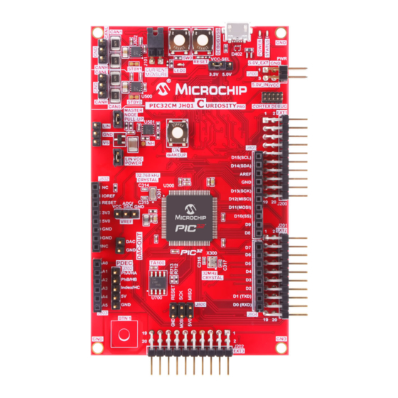
PIC32CM JH01 Curiosity Pro evaluation kit is a hardware platform to evaluate the Microchip
PIC32CM JH01 microcontroller (MCU). Each evaluation kit is supported by the MPLAB
Environment (IDE) and MPLAB
The Curiosity Pro evaluation kits include an on-board embedded debugger (EDBG) to program or debug the target
microcontroller. This enables an easy start to a project, and provides application examples that can be used in the
design of a custom application.
The Curiosity Pro evaluation kits provide easy access to the features of the microcontroller, and are integrated
with Arduino Uno, mikroBUS
prototyping and expanded functionality. The figure below shows the PIC32CM JH01 Curiosity Pro evaluation kit.
Figure 1. PIC32CM JH01 Curiosity Pro Evaluation kit
©
2022 Microchip Technology Inc.
and its subsidiaries
®
Harmony v3, featuring application examples.
™
, and extension headers to interface with Xplained Pro extension boards for a rapid
User Guide
EV81X90A
®
X Integrated Development
DS70005482B-page 1
Advertisement
Table of Contents

Related Manuals for Microchip Technology PIC32CM JH01


Summary of Contents for Microchip Technology PIC32CM JH01
-
Page 1: Preface
Arduino Uno, mikroBUS , and extension headers to interface with Xplained Pro extension boards for a rapid prototyping and expanded functionality. The figure below shows the PIC32CM JH01 Curiosity Pro evaluation kit. Figure 1. PIC32CM JH01 Curiosity Pro Evaluation kit... -
Page 2: Table Of Contents
The Microchip Website..........................34 Product Change Notification Service......................34 Customer Support............................34 Microchip Devices Code Protection Feature....................34 Legal Notice..............................35 Trademarks..............................35 Quality Management System........................36 Worldwide Sales and Service........................37 User Guide DS70005482B-page 2 © 2022 Microchip Technology Inc. and its subsidiaries... -
Page 3: Introduction
EV81X90A Introduction Introduction Features The following are key features of the PIC32CM JH01 Curiosity Pro evaluation kit. • 100-pin TQFP PIC32CM5164 JH01 microcontroller • Embedded Debugger – micro-USB interface – Auto-ID for daughter board identification in MPLAB X IDE – One yellow status LED –... -
Page 4: Overview
EV81X90A. The evaluation kit offers a set of features that enables the PIC32CM JH01 users to get started with the PIC32CM JH01 peripherals, and to obtain an understanding of how to integrate the device in their own design. The following figure illustrates the top and bottom view of the PIC32CM JH01 Curiosity Pro evaluation kit. - Page 5 EV81X90A Introduction Figure 1-2. PIC32CM JH01 Curiosity Pro Evaluation Kit Layout (Bottom View) User Guide DS70005482B-page 5 © 2022 Microchip Technology Inc. and its subsidiaries...
- Page 6 PDEC header connectors Trust Anchor 100 (TA100) secure element Target Voltage power switch with slew rate control Embedded Debugger (EDBG) Table 1-2. PIC32CM JH01 Curiosity Pro Evaluation Kit Microchip Total System Solutions (TSS) TSS Component Qty (Per Kit) Function PIC32CM5164JH01100-I/PF Target MCU MIC5504-3.3YM5-TR...
-
Page 7: Getting Started
The kit landing page in MPLAB X IDE also has an option to launch MPLAB Harmony v3 example applications for the kit. The PIC32CM JH01 device is programmed and debugged by the on-board Embedded Debugger (EDBG), hence no external programmer or debugger tool is required. -
Page 8: Curiosity Pro
Note: The virtual COM port in the EDBG requires the terminal software to set the data terminal ready (DTR) signal to enable the UART pins connected to the PIC32CM JH01. If the DTR signal is not enabled, the UART pins on the EDBG are kept in high-z (tristate) rendering the COM port unusable. -
Page 9: Hardware User Guide
If the selected voltage is within the connected extensions ranges, the switch will open. If not, the EDBG power LED will blink rapidly and the switch will stay closed resulting in no power provided to the PIC32CM JH01, on-board peripherals, and connectors. - Page 10 Hardware User Guide Figure 4-1. Power Supply Block Diagram VCC_P5V0 VCC_P3V3 EDBG Regulator 3.3V EDBG USB Auto MUX Power Select External 5V Input (Jumper) Power Switch Power source VCC_MCU Power switch VCC_TARGET Jumper Power converter PIC32CM JH01 Peripherals Power consumer User Guide DS70005482B-page 10 © 2022 Microchip Technology Inc. and its subsidiaries...
-
Page 11: Headers And Connectors
The following sections describe the implementation of the relevant connectors and headers on the evaluation kit and their connection to the PIC32CM JH01 microcontroller. The tables of connections below also describe which signals are shared between the headers and on-board functionality. - Page 12 SERCOM1/PAD[1] SPI 15 [SPI_SS_A] PC28 PC28_SPI_SS_A SERCOM1/PAD[2] SPI 16 [SPI_MOSI] PA18 PA18_SPI_MOSI MOSI SERCOM1/PAD[0] SPI 17 [SPI_MISO] PC27 PC27_SPI_MISO MISO SERCOM1/PAD[3] SPI 18 [SPI_SCK] PA19 PA19_SPI_SCK 19 [GND] Ground. User Guide DS70005482B-page 12 © 2022 Microchip Technology Inc. and its subsidiaries...
- Page 13 TA100 SPI MOSI SERCOM5/PAD[0] 17 [SPI_MISO] PB02 PB02_SPI_MISO TA100 SPI MISO SERCOM5/PAD[3] 18 [SPI_SCK] PB01 PB01_SPI_SCK TA100 SPI SCK 19 [GND] Ground. Power for extension 20 [VCC] board. User Guide DS70005482B-page 13 © 2022 Microchip Technology Inc. and its subsidiaries...
- Page 14 SERCOM7/PAD[0] SPI 17 [SPI_MISO] PC12 PC12_SPI_MISO EDBG DGI, Arduino MISO SERCOM7/PAD[3] SPI 18 [SPI_SCK] PC15 PC15_SPI_SCK EDBG DGI, Arduino 19 [GND] Ground Power for extension 20 [VCC] board. User Guide DS70005482B-page 14 © 2022 Microchip Technology Inc. and its subsidiaries...
- Page 15 Hardware User Guide ™ 4.2.2 Arduino Uno Header Connectors The PIC32CM JH01 Curiosity Pro evaluation kit implements Arduino shield connectors based on the Arduino Uno. All references to the Arduino pin names are taken from the official Arduino schematics of the Arduino Uno.
- Page 16 PC15_SPI_SCK EXT3, EDBG DGI SPI SCK Ground PA03 AREF PA03_ADC_DAC_VREF SERCOM1/PAD[0] EXT2, EXT3, EDBG PA16 SDA/D14 PA16_I2C_SDA C SDA SERCOM1/PAD[1] EXT2, EXT3, EDBG PA17 SCL/D15 PA17_I2C_SCL C SCL User Guide DS70005482B-page 16 © 2022 Microchip Technology Inc. and its subsidiaries...
- Page 17 The evaluation kit has a 3-pin header, labeled VCC_SEL. This header can be used to select between 3.3V and 5.0V as the supply voltage for the PIC32CM JH01, peripherals, and extension headers by placing a jumper on the pin 1-2 or pin 2-3.
- Page 18 An angled 1x2, 100 mil pin-header labeled CURRENT MEASURE is located at the upper edge of the evaluation kit. All power to the PIC32CM JH01 is routed through this header. To measure the power consumption of the device, remove the jumper and replace it with an ammeter.
-
Page 19: Peripherals
Mechanical Buttons The evaluation kit contains two mechanical buttons connected to the PIC32CM JH01. One button is the RESET button connected to the reset line, and the other is a generic user configurable button. When a button is pressed, it will drive the I/O line to GND. - Page 20 EV81X90A Hardware User Guide 4.3.4 The PIC32CM JH01 has two CAN modules that perform communications according to ISO11898-1 (Bosch CAN specification 2.0 part A,B) and Bosch CAN FD specification V1.0. Each CAN (CAN0 and CAN1) are connected to an on-board ATA6561 CAN physical-layer transceiver.
- Page 21 ATA663211 LIN transceiver is mounted on the kit to convert the LIN signals from the SERCOM module in the PIC32CM JH01 device. The LIN compatible signals are available as a 3-pin header. Table 4-24. U501 - LIN Transceiver PIC32CM JH01...
- Page 22 4.3.7 Trust Anchor 100 (TA100) Secure Element The TA100 Secure Element device requires a SPI interface to work and communicate with the PIC32CM JH01. The following table shows all the connections between the TA100 and the PIC32CM JH01. Table 4-29. U700 - TA100 Connections...
-
Page 23: Kit Modifications
The evaluation kit has several resistors and jumpers that can be removed or cut to disconnect the I/O pins of the PIC32CM JH01 from the connectors and the on-board ICs to disconnect and measure power to different sections. Table 4-30. Resistors... - Page 24 EV81X90A Hardware User Guide The following figures illustrate the top and bottom view of the resistors. Figure 4-2. Resistors (Top View) User Guide DS70005482B-page 24 © 2022 Microchip Technology Inc. and its subsidiaries...
- Page 25 EV81X90A Hardware User Guide Figure 4-3. Resistors (Bottom View) User Guide DS70005482B-page 25 © 2022 Microchip Technology Inc. and its subsidiaries...
- Page 26 CAN 0 transceiver (ATA6561). J506 CAN 1 device, Standby pin Cut this jumper to explore the standby functionality of the CAN 1 transceiver (ATA6561). User Guide DS70005482B-page 26 © 2022 Microchip Technology Inc. and its subsidiaries...
- Page 27 EV81X90A Hardware User Guide The following figures illustrates the top and bottom view of the jumpers. Figure 4-4. Jumpers (Top View) User Guide DS70005482B-page 27 © 2022 Microchip Technology Inc. and its subsidiaries...
- Page 28 EV81X90A Hardware User Guide Figure 4-5. Jumpers (Bottom View) User Guide DS70005482B-page 28 © 2022 Microchip Technology Inc. and its subsidiaries...
-
Page 29: Embedded Debugger Implementation
The Embedded Debugger features a Data Gateway Interface (DGI) by using either a SPI or I²C interface. The DGI can be used to send a variety of data from the PIC32CM JH01 to the Host PC. For additional information on using the DGI interface, refer to the Data Gateway Interface User’s Guide... - Page 30 EV81X90A Hardware User Guide Table 4-36. GPIO Lines Connected to the EDBG PIC32CM JH01 pin Function Schematic Net Name Shared functionality PC00 DGI_GPIO0 PC00_DGI_GPIO0 PC03 DGI_GPIO1 PC03_DGI_GPIO1 PC02 DGI_GPIO2 PC02_DGI_GPIO2 PC01 DGI_GPIO3 PC01_DGI_GPIO3 User Guide DS70005482B-page 30 © 2022 Microchip Technology Inc.
-
Page 31: Identifying Product Id And Revision
The evaluation kit serial number string has the following format: MCHPnnnnrrssssssssss Where, n = Product Identifier r = Revision s = Board number Table 5-1. PIC32CM JH01 Curiosity Pro Evaluation Kit Product Identifiers Family Product Identifier PIC32CM JH01 3053 User Guide DS70005482B-page 31 ©... -
Page 32: References
EV81X90A References References • PIC32CM JH00/JH01 Family Data Sheet (DS60001632) • PIC32CM JH00/JH01 Family Silicon Errata and Data sheet Clarifications (DS80001000) User Guide DS70005482B-page 32 © 2022 Microchip Technology Inc. and its subsidiaries... -
Page 33: Revision History
Terminology in this document may not match with the contents of the current revision of the device data sheet or other Microchip documentation and collateral. If there are any questions or concerns regarding terminology, please contact a Microchip Support or Sales Representative. User Guide DS70005482B-page 33 © 2022 Microchip Technology Inc. and its subsidiaries... -
Page 34: The Microchip Website
Attempts to break Microchip’s code protection feature may be a violation of the Digital Millennium Copyright Act. If such acts allow unauthorized access to your software or other copyrighted work, you may have a right to sue for relief under that Act. User Guide DS70005482B-page 34 © 2022 Microchip Technology Inc. and its subsidiaries... -
Page 35: Legal Notice
The Adaptec logo, Frequency on Demand, Silicon Storage Technology, and Symmcom are registered trademarks of Microchip Technology Inc. in other countries. GestIC is a registered trademark of Microchip Technology Germany II GmbH & Co. KG, a subsidiary of Microchip Technology Inc., in other countries. -
Page 36: Quality Management System
EV81X90A Quality Management System For information regarding Microchip’s Quality Management Systems, please visit www.microchip.com/quality. User Guide DS70005482B-page 36 © 2022 Microchip Technology Inc. and its subsidiaries... -
Page 37: Worldwide Sales And Service
Tel: 631-435-6000 Sweden - Stockholm San Jose, CA Tel: 46-8-5090-4654 Tel: 408-735-9110 UK - Wokingham Tel: 408-436-4270 Tel: 44-118-921-5800 Canada - Toronto Fax: 44-118-921-5820 Tel: 905-695-1980 Fax: 905-695-2078 User Guide DS70005482B-page 37 © 2022 Microchip Technology Inc. and its subsidiaries...
Need help?
Do you have a question about the PIC32CM JH01 and is the answer not in the manual?
Questions and answers