Table of Contents
Advertisement
Quick Links
PIC18F47K42 Curiosity Nano
PIC18F47K42 Curiosity Nano Hardware User Guide
Preface
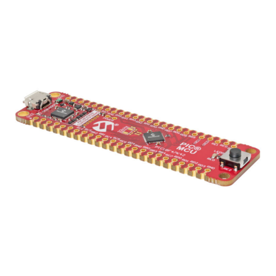
The PIC18F47K42 Curiosity Nano Evaluation Kit is a hardware platform to evaluate the PIC18F47K42 microcontroller
(MCU).
®
Supported by Microchip MPLAB
X Integrated Development Environment (IDE), the kit provides easy access to the
features of the PIC18F47K42 to explore how to integrate the device into a custom design.
The Curiosity Nano series of evaluation kits include an on-board debugger. No external tools are necessary to
program and debug the PIC18F47K42.
User Guide
DS50002899B-page 1
©
2019 Microchip Technology Inc.
Advertisement
Table of Contents

Subscribe to Our Youtube Channel
Related Manuals for Microchip Technology PIC18F47K42 Curiosity Nano


Summary of Contents for Microchip Technology PIC18F47K42 Curiosity Nano
-
Page 1: Preface
PIC18F47K42 Curiosity Nano PIC18F47K42 Curiosity Nano Hardware User Guide Preface The PIC18F47K42 Curiosity Nano Evaluation Kit is a hardware platform to evaluate the PIC18F47K42 microcontroller (MCU). ® Supported by Microchip MPLAB X Integrated Development Environment (IDE), the kit provides easy access to the features of the PIC18F47K42 to explore how to integrate the device into a custom design. -
Page 2: Table Of Contents
PIC18F47K42 Curiosity Nano Table of Contents Preface................................1 Introduction............................. 3 1.1. Features............................3 1.2. Kit Overview..........................3 Getting Started............................4 ® 2.1. Curiosity Nano Quick Start MPLAB Xpress................4 2.2. Curiosity Nano Quick Start......................4 2.3. Design Documentation and Relevant Links................. 4 Curiosity Nano............................6... -
Page 3: Introduction
– 2.3-5.1V output voltage (limited by USB input voltage) – 500 mA maximum output current (limited by ambient temperature and output voltage) Kit Overview The Microchip PIC18F47K42 Curiosity Nano Evaluation Kit is a hardware platform to evaluate the PIC18F47K42 microcontroller. Figure 1-1. PIC18F47K42 Curiosity Nano Evaluation Kit Overview... -
Page 4: Getting Started
The PIC18F47K42 device is programmed and debugged by the on-board debugger and therefore no external programmer or debugger tool is required. Design Documentation and Relevant Links The following list contains links to the most relevant documents and software for the PIC18F47K42 Curiosity Nano: ® ®... - Page 5 PIC18F47K42 Curiosity Nano Getting Started • PIC18F47K42 Curiosity Nano website - Kit information, latest user guide and design documentation. • PIC18F47K42 Curiosity Nano on microchipDIRECT - Purchase this kit on microchipDIRECT. User Guide DS50002899B-page 5 © 2019 Microchip Technology Inc.
-
Page 6: Curiosity Nano
PIC18F47K42 and provides an easy way to communicate with the target application through terminal software. The on-board debugger controls a Power and Status LED (marked PS) on the PIC18F47K42 Curiosity Nano. The table below shows how the LED is controlled in different operation modes. - Page 7 PIC18F47K42 Curiosity Nano Curiosity Nano Info: On older Windows systems, a USB driver is required for CDC. This driver is included in MPLAB X IDE and Atmel Studio installations. 3.1.1.2 Limitations Not all UART features are implemented in the on-board debugger CDC. The constraints are outlined here: •...
- Page 8 PIC18F47K42 Curiosity Nano Curiosity Nano When receiving data from the target, the on-board debugger will queue up the incoming bytes into 64-byte frames, which are sent to the USB queue for transmission to the host when they are full. Incomplete frames are also pushed to the USB queue at approximately 100 ms intervals, triggered by USB start-of-frame tokens.
-
Page 9: Curiosity Nano Standard Pinout
PIC18F47K42 Curiosity Nano Curiosity Nano Curiosity Nano Standard Pinout The 12 edge connections closest to the USB connector on Curiosity Nano kits have a standardized pinout. The program/debug pins have different functions depending on the target programming interface as shown in the table and figure below. - Page 10 1.7V to 5.1V. Additional output voltage limits are configured in the debugger firmware to ensure that the output voltage never exceeds the hardware limits of the PIC18F47K42 microcontroller. The voltage limits configured in the on-board debugger on PIC18F47K42 Curiosity Nano are 2.3-5.1V.
- Page 11 VBUS Output Pin PIC18F47K42 Curiosity Nano has a VBUS output pin which can be used to power external components that need a 5V supply. The VBUS output pin has a PTC fuse to protect the USB against short circuits. A side effect of the PTC fuse is a voltage drop on the VBUS output with higher current loads.
-
Page 12: Target Current Measurement
PIC18F47K42 Curiosity Nano Curiosity Nano Figure 3-4. VBUS Output Voltage vs. Current Target Current Measurement Power to the PIC18F47K42 is connected from the on-board power supply and VTG pin through a 100-mil pin header cut Target Power strap marked with “POWER” in silkscreen (J101). To measure the power consumption of the PIC18F47K42 and other peripherals connected to the board, cut the Target Power strap and connect an ammeter over the strap. -
Page 13: Disconnecting The On-Board Debugger
Disconnecting the On-Board Debugger The block diagram below shows all connections between the debugger and the PIC18F47K42 microcontroller. The rounded boxes represent connections to the board edge on PIC18F47K42 Curiosity Nano. The signal names shown Figure 3-1 are printed in silkscreen on the bottom side of the board. - Page 14 PIC18F47K42 Curiosity Nano Curiosity Nano Figure 3-7. Kit Modifications GPIO straps (bottom side) Power Supply strap (top side) User Guide DS50002899B-page 14 © 2019 Microchip Technology Inc.
-
Page 15: Hardware User Guide
Using Pin Headers The edge connector footprint on PIC18F47K42 Curiosity Nano has a staggered design where each of the holes is shifted 8 mil (~0.2 mm) off center. The hole shift allows the use of regular 100-mil pin headers on the kit without soldering. -
Page 16: Peripherals
Peripherals 4.2.1 There is one yellow user LED available on the PIC18F47K42 Curiosity Nano kit that can be controlled by either GPIO or PWM. The LED can be activated by driving the connected I/O line to GND. Table 4-1. LED Connection... - Page 17 Edge connector 4.2.4 On-Board Debugger Implementation PIC18F47K42 Curiosity Nano features an on-board debugger that can be used to program and debug the PIC18F47K42 using ICSP. The on-board debugger also includes a Virtual COM port (CDC) interface over UART and ®...
-
Page 18: Hardware Revision History And Known Issues
Identifying Product ID and Revision The revision and product identifier of the PIC18F47K42 Curiosity Nano can be found in two ways; either through ® Microchip MPLAB X IDE or by looking at the sticker on the bottom side of the PCB. -
Page 19: Document Revision History
PIC18F47K42 Curiosity Nano Document Revision History Document Revision History Doc. rev. Date Comment 10/2019 Updated for rev 2 of kit. 06/2019 Initial document release. User Guide DS50002899B-page 19 © 2019 Microchip Technology Inc. -
Page 20: Appendix
PIC18F47K42 Curiosity Nano Appendix Appendix Schematic Figure 7-1. PIC18F47K42 Curiosity Nano Schematic User Guide DS50002899B-page 20 © 2019 Microchip Technology Inc. - Page 21 PIC18F47K42 Curiosity Nano Appendix User Guide DS50002899B-page 21 © 2019 Microchip Technology Inc.
-
Page 22: Assembly Drawing
PIC18F47K42 Curiosity Nano Appendix Assembly Drawing Figure 7-2. PIC18F47K42 Curiosity Nano Assembly Drawing Top PIC® Figure 7-3. PIC18F47K42 Curiosity Nano Assembly Drawing Bottom User Guide DS50002899B-page 22 © 2019 Microchip Technology Inc. -
Page 23: Curiosity Nano Base For Click Boards
PIC18F47K42 Curiosity Nano Appendix ™ Curiosity Nano Base for Click boards Figure 7-4. PIC18F47K42 Curiosity Nano Pinout Mapping VBUS DBG3 (RC0) VOFF DBG0 (RC1) CDC TX DBG2 CDC RX DBG1 User Guide DS50002899B-page 23 © 2019 Microchip Technology Inc. -
Page 24: Connecting External Debuggers
PIC18F47K42 Curiosity Nano Appendix Connecting External Debuggers Even though there is an on-board debugger, external debuggers can be connected directly to the PIC18F47K42 Curiosity Nano to program/debug the PIC18F47K42. The on-board debugger keeps all the pins connected to the PIC18F47K42 and board edge in tri-state when not actively used. Therefore, the on-board debugger will not interfere with any external debug tools. -
Page 25: The Microchip Website
PIC18F47K42 Curiosity Nano The Microchip Website Microchip provides online support via our website at http://www.microchip.com/. This website is used to make files and information easily available to customers. Some of the content available includes: • Product Support – Data sheets and errata, application notes and sample programs, design resources, user’s guides and hardware support documents, latest software releases and archived software •... -
Page 26: Trademarks
The Adaptec logo, Frequency on Demand, Silicon Storage Technology, and Symmcom are registered trademarks of Microchip Technology Inc. in other countries. GestIC is a registered trademark of Microchip Technology Germany II GmbH & Co. KG, a subsidiary of Microchip Technology Inc., in other countries. -
Page 27: Worldwide Sales And Service
New York, NY Tel: 46-31-704-60-40 Tel: 631-435-6000 Sweden - Stockholm San Jose, CA Tel: 46-8-5090-4654 Tel: 408-735-9110 UK - Wokingham Tel: 408-436-4270 Tel: 44-118-921-5800 Canada - Toronto Fax: 44-118-921-5820 Tel: 905-695-1980 Fax: 905-695-2078 User Guide DS50002899B-page 27 © 2019 Microchip Technology Inc. - Page 28 Mouser Electronics Authorized Distributor Click to View Pricing, Inventory, Delivery & Lifecycle Information: Microchip DM182028...
Need help?
Do you have a question about the PIC18F47K42 Curiosity Nano and is the answer not in the manual?
Questions and answers